Christoph Tack
-
Board bring up & evaluation
06/24/2020 at 08:24 • 0 commentsRevision 1
In first instance, we'll try to compare the performance with the #TritiLED. In order to do that, we'll assemble the following variant:
- Placing R8 instead of the TPL5110 circuit so that the LED doesn't flash. This will make it easier to measure power supply current.
- Placing R11 and R4, effectively using only one LED.
First of all: add a little bit of solder to the GND pad of the CR2032. If you don't do it, you risk having an unreliable ground connection to your cell because the GND pad lies deeper than the surrounding solder mask.
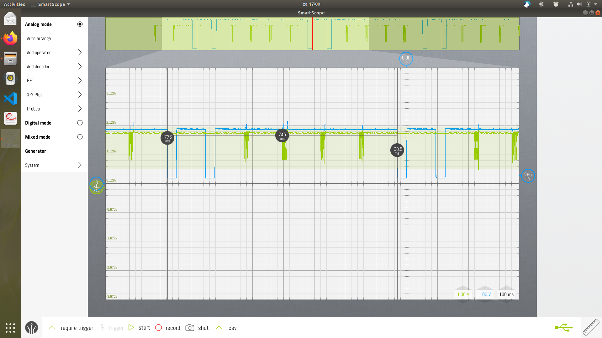
After soldering CN1 up to U2 by hand, we could start programming U2. This went alright and now U2 outputs a 64Hz square wave on its CLKO-pin.
I measured the power supply current by feeding the circuitry through a 100K-resistor to CN1. In parallel with CN1 I put some elco's with a total value of around 10µF. At power up, the 100K resistor needs to be short circuited. After that, the short circuit can be removed to measure current : 56nA with a 3V3 power supply.
Now U5 and its peripheral components could be soldered as well. The package of U5 is too wide, but soldering the component is still possible. C7 had to be increased to 22pF to get an output pulse of about 3.2µs. The current consumption now is 73nA using a 3V3 power supply.
The LED driver circuitry, the only circuit that hadn't been fully bread boarded beforehand doesn't perform well enough. See the LED driver log for more info.
The CR2032 clip needs a bigger outline. If you insert the cell too deep, you could create short circuits with other circuitry.
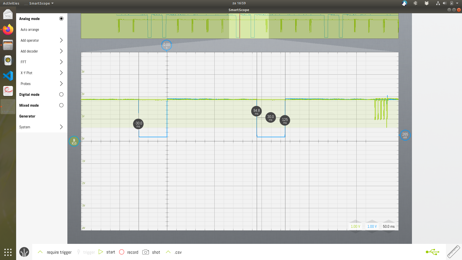
The RTC needs to be constantly on, because it takes 250ms for it to fully initialize. During the initialization phase it likely draws much more current. The TPL5110 will not be used to power the RTC and other circuitry on. The TPL5110 will only enable the one-shot timer at regular intervals.
Revision 2
The 100nF for C5 and C7 were not enough to avoid the bright LED flash at power up. C5 has been increased to 1µF. C7 has been put to not-placed.
The placement of L2 limits the viewing angle of the LED. I placed L1 instead and shortcircuited L2 with the 0ohm resistor.
Evaluation
- The LED is too bright according to my wife. This led her to covering the LED with paper tape.
- The device often lingers on the floor. It happened twice that someone stepped on it, leading to a crushed housing. A sturdier housing would be welcome.
- The big inductor is more fragile than expected. In a few months time, I replaced three broken ones. So I covered the inductor with hot glue. 2-component epoxy might work as well.
-
References
05/16/2020 at 18:42 • 0 comments- TritiLED : a continuously ON LED, Decade flashlight is derived from this.
- The discrete version flashes at 35Hz, with an ON-time for the switching transistor of 12µs. The peak inductor current is dI = V * dt / L = 3 * 12µ / 1m = 36mA (but only 24mA is attained in the circuit) : 11.5µA.
- The PIC-version uses 1.2µs pulses for the 4mA peak efficiency of the OSLON Signal Verde LED: 12.5µA.
- For a pulse frequency of 55Hz, the current consumption is 6.12µA.
- https://hackaday.io/project/28344-10-year-led-flasher
- 50µA current consumption from a 1.5V cell
- https://www.nutsvolts.com/magazine/article/practical-led-indicator-and-flasher-circuits
- reference to human eye reaction
- https://www.electroschematics.com/led-flasher-circuits/
- https://electronics.stackexchange.com/questions/51547/simple-energy-efficient-circuit-to-make-single-ir-led-blink
- http://www.discovercircuits.com/H-Corner/lowpwrflasher.htm
- using a comparator
- https://arduinoelectronics.wordpress.com/2014/01/06/ultra-low-power-led-flasher-with-attiny
- using a microcontroller
- using resistor in series with LED
- https://github.com/hexagon5un/everled
- using an attiny45
- using LED as flyback diode to an inductor
- http://pigeonsnest.co.uk/stuff/picprog/single-cell-led-flasher-two-year-battery-life.html (<50µA)
- Flasher circuits
- Led torch circuits includes an improved version of Modified joule thief
- Simplified white-LED flasher operates from one cell
- TritiLED : a continuously ON LED, Decade flashlight is derived from this.
-
Power source
05/16/2020 at 18:31 • 0 commentsCoin cell CR2032
These really DO NOT like current spikes. So a lot of buffer capacitance will be needed to buffer the LED current spike. Data from Energizer:
- 235mAh downto 2V, rated for 190µA load
- Lithium / Manganese Dioxide (Li/MnO 2 )
Battery life calculations show that the project could run about 1 year when ON-current is 5mA and OFF-current is limited to 1µA.
3V CR123A Lithium cells
store up to 1700mAh. These will last a lot longer. Unfortunately they're much bigger : 34.5mm x ⌀17.0 mm
LIR2450
If a rechargeable solution is desired, then the 3.7V/120mAh LIR2450 can be used. This cell tolerates current spikes much better.
The dimensions are acceptable as well 5.0mm x ⌀24.5 mm
Charger : Hackaday.io charger
-
Design V1
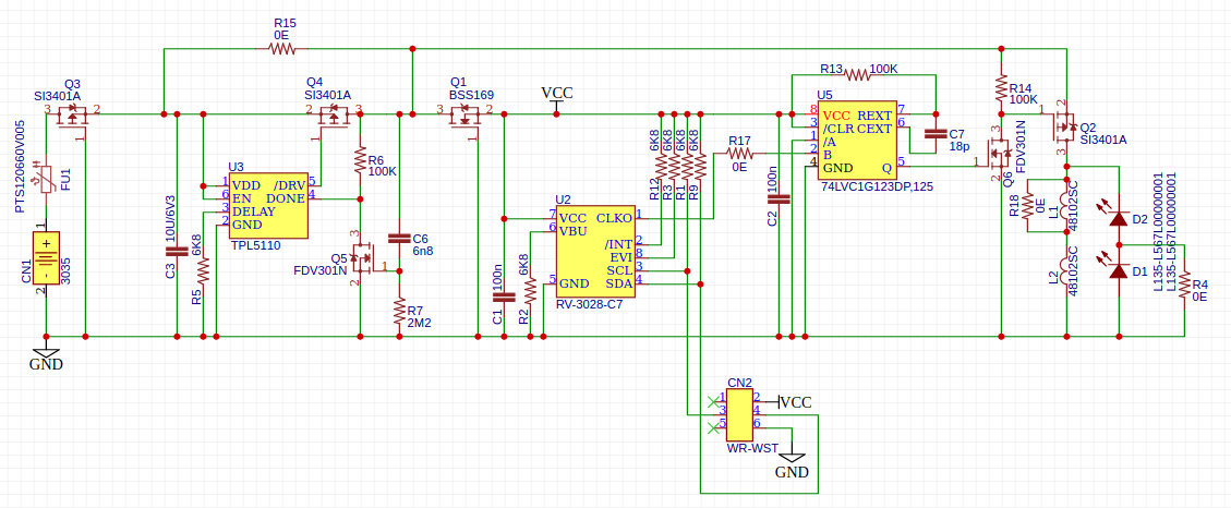
05/01/2020 at 08:30 • 0 commentsSchematic
![]()
Schematic of R1 Power & protection section
The board is powered by a CR2032-cell inserted in CN1. FU1 is a 50mA fuse, it could be replaced by a 100ohm resistor.
Q3 is a reverse polarity protection to protect the circuit when the CR2032 is incorrectly inserted.
C3 smooths out the current spikes from the LEDs.
Flashing section
If flashing is not needed, instead of this section, place R15.
Functionality of this section is described in Testing the TPL5110.
The TPL5110 requires about 35nA.
Oscillator section
The RV-3028-C7 is an RTC. After its internal EEPROM is programmed, it will output a 64Hz square wave on the CLKO-pin.
This RTC can be programmed using the debug connector CN2. Any I²C-master could be used to program the RTC. CN2 is designed for the WR-WST IDC connector. It allows for easy connection and removal of a programming adapter.
The RV-3028-C7 requires about 45nA.
One-shot section
The 74xx123 is a one-shot timer. To reduce power consumption, its supply voltage is lowered to about 2V using Q1. Because U2 drives U5, U2 also needs to run on this lower supply voltage to prevent over-driving the B-input of U5.
The value of C7 requires some experimenting to fine tune. R17 can be removed to connect a function generator to pin B of U5, which will make experimenting easier.
The one-shot timer will produce a positive outgoing pulse when triggered.
The pull-up resistors are all 6K8. Their value isn't critical, so I reused the 6K8 from the flashing section to reduce the number of different BoM-items.
The current consumption needs to be measured it. At room temperature, it will only be a few hundred nA probably.
LED driver section
To drive the LEDs an NMOS with a low RdsOn could be directly connected to pin 5 of U5. To limit the number of different components in the design, I opted for reusing the FDV301 and the SI3401 instead. If this design would be produced in large quantities, the extra cost of logistics for an extra BoM-item would be far greater than the cost of an extra SI3401.
The 0ohm resistors allow to choose the number of inductors or the number of LEDs.
The inductors require a lot of PCB-space. Keep in mind that two of these 1mH coils are cheaper than one 2mH inductor with comparable specs. This is a design trade-off again: size for cost.
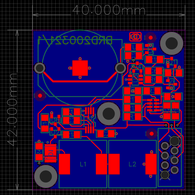
PCB-Layout
The size of the PCB should match a TikTak-box.
There are two diagonally placed mounting holes. Their use is not defined yet.
The 3mm mounting hole in the center if for mounting a neodymium magnet with a 3mm center hole.
One LED is on bottom side. The other one is on top side like the rest of the components. So one LED will be visible at all times.
![]()
-
"One shot timer" aka "Monostable multivibrator"
04/13/2020 at 20:04 • 0 commentsAs #TritiLED does it on design V3.0, the MCU sleeps while two PWMs remain active. The first PWM controls the power to the 74xx123, the second PWM initiates the pulse.
74LVC1G123
-
LED choice
04/11/2020 at 19:31 • 0 commentsLumileds Luxeon 3535L Lime
- Digikey 1416-1440-1-ND
- 184lm/W
- optimum efficiency from 1mA to 30mA (didn't measure higher current because of lack of heatsink).
- Best efficiency at 5mA. It's then 8% better than at 1mA or 30mA. This has been measured with a TSL2591 connected to a Protrinket 3V and the LED mounted about 10mm directly above it. A current source controls the LED current, while a DMM is used to measure the LED voltage. A more decent setup can be found here.
Osram Oslon Signal Verde
- Digikey 475-3450-1-ND
- used in #TritiLED
- 61lm/W to 130lm/W depending on packing unit
Cree XLamp XP-E2 Green
- Digikey XPEBGR-L1-0000-00F02CT-ND
- used in #TritiLED
- 113lm/W
-
Low power ambient light switch
04/08/2020 at 18:47 • 0 commentsNot much use is it to light an LED when there's already plenty of light around? So how to switch on the LED only when the ambient light level is low enough?
The two circuits mentioned below have been built on breadboard to test the ambient light switch functionality.
The current consumption of this ambient light switch adds considerably to the total current consumption of the design. Let's do a quick calculation:
- without ambient switch : assume 1.7µA continuous
- with ambient switch :
- day : 1.5µA (LED off)
- night : 2µA (LED on)
So what should be the night/day ratio to benefit from the ambient light sensor?
If there's less than 40% of night, then we start benefiting from this, but the gains are marginal. It doesn't weigh up against the extra cost, and required PCB area.
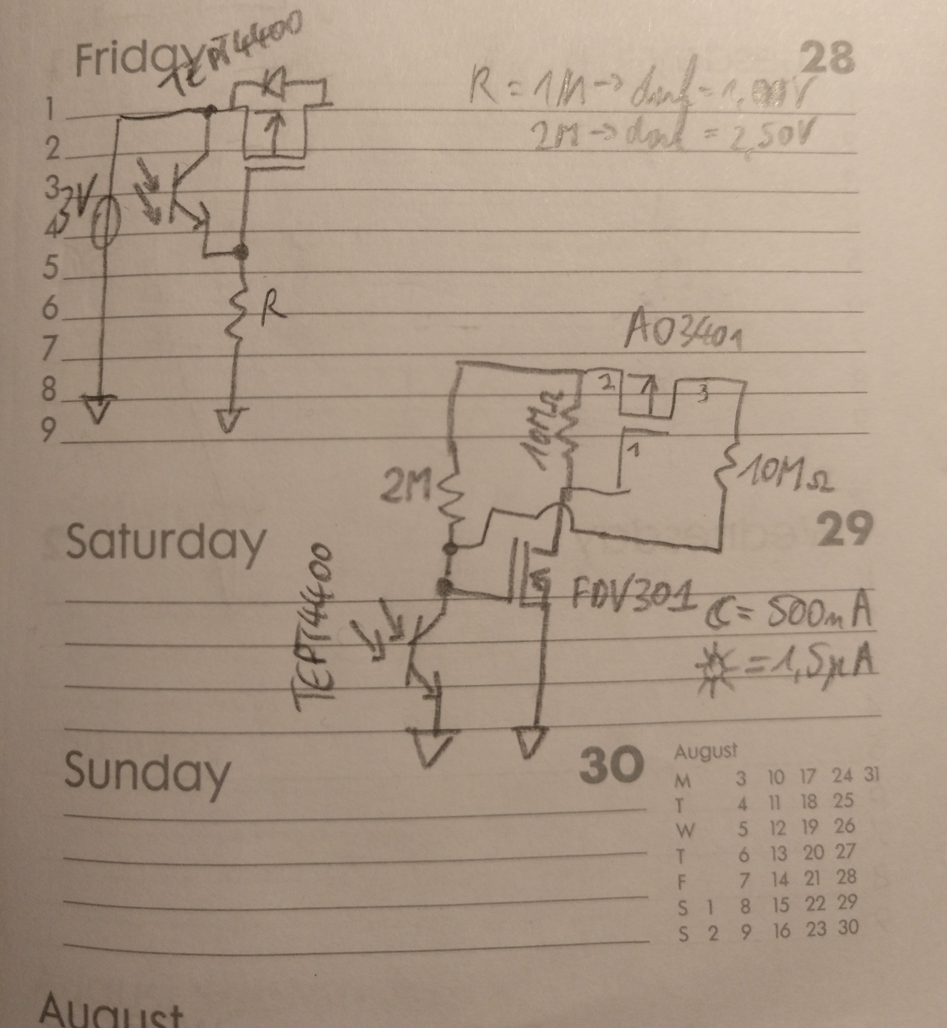
Simplistic approach
A photo transistor is connected across the drain-source of a PMOS. The disadvantage is that the transition of light to dark is not hard. There's a region where the PMOS isn't fully conducting.
![]()
Pencil schematic on diary page Schmitt-trigger approach
By adding an extra NMOS resistor we can improve this circuit. The extra inverting effect of the FDV301 allows to make a feed-forward compensation with the 10Mohm resistor on the drain of the PMOS. As such, there's a hard switching threshold for the PMOS. The PMOS will be either OFF or ON, nothing in between.
Current consumption is 1.5µA (3V / 2Mohm) during daylight. At night, this drops to 300nA.
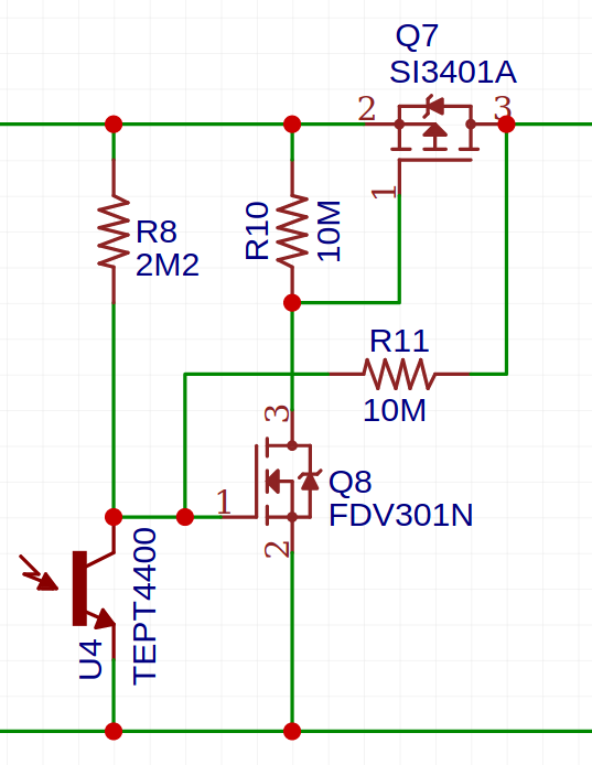
![]()
Cutout from schematic, 3V cell is connected on the left, while the load is connected to the right. Solar cell
The solar cell could actually generate power when being lit, instead of consuming current as the other circuits do.
I haven't investigated yet how to use it as a switch. Energy could be harvested and stored in a supercap.
Interesting circuits to be found here.
-
Oscillators
04/04/2020 at 20:19 • 0 commentsThree technologies have been investigated:
Real Time Clocks
Real Time Clocks are low power components. Some only consume 45nA on a 3V power supply. They also provide a clock output which could be used to trigger the LED pulses.
Let's investigate the RV-3028-C7 32.768KHZ 1PPM-TA-QC
- 40nA @ 3V
- 1 ppm @ 25°C, 20ppm from 0°C to 50°C, 140ppm from -40°C to 85°C (nope, this won't be used for industrial applications)
- 64Hz clock output
- €2.47/pce
The idea would be to use an MCU that sets up the RTC and then goes to deep sleep forever. The RTC then functions as a very stable, but expensive 64Hz oscillator. As the clock setting in the RTC is stored in EEPROM, it only needs to be written once in the lifetime of the product. The MCU is not even necessary on the finished product!
Remark that neither the ATtiny4, nor the ATtiny13A have built-in I²C-support. After implementing a bit banged I²C library, I realized that it wasn't needed after all. I'd better used an FT232H, RPi or STM32 to program the RTC. I ended up doing it with an Adafruit Protrinket 3V.
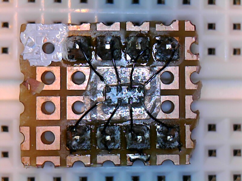
To measure the current consumption of the RV-3028-C7, a 1Mohm sense resistor has been put in series with the GND connection. Short-circuit the sense resistor on power up. Once the square wave is output, you can open the short circuit over the sense resistor and start measuring.
Be sure to take the internal resistance of your DMM into account. If you have no clue what it is, put a 1Mohm resistor in series with your DMM and connect it to 3V3, while the COM-lead of your DMM is connected to GND. If your DMM had an ideal infinite resistance, you'd still be measuring 3.3V. In my case the voltage dropped to 3V0. So my DMM has an internal resistance of 10Mohm. This makes that the actual value of the sense resistor is 1Mohm in parallel with 10Mohm = 909Kohm.
Current consumption was 46nA at a supply voltage of 3.3V and an ambient temperature of about 20°C. Nothing was connected to CLKOUT. Remember that connecting even your 10x scope probe will load the CLKOUT with 10Mohm, resulting in an extra current consumption of about 120nA.
![]()
Breadboarding the RV-3028-C7 using a piece of breadboard, double sided tape, Roadrunner wiring pencil, a soldering iron and a microscope. Instead of breadboarding this yourself, you could buy the breakout board from Pimoroni or the breakout board from Sparkfun instead. Remark that the Sparkfun board is a breakout to banana plugs, not to 0.1" pin headers. Don't be mistaken by its size.
Power up problem
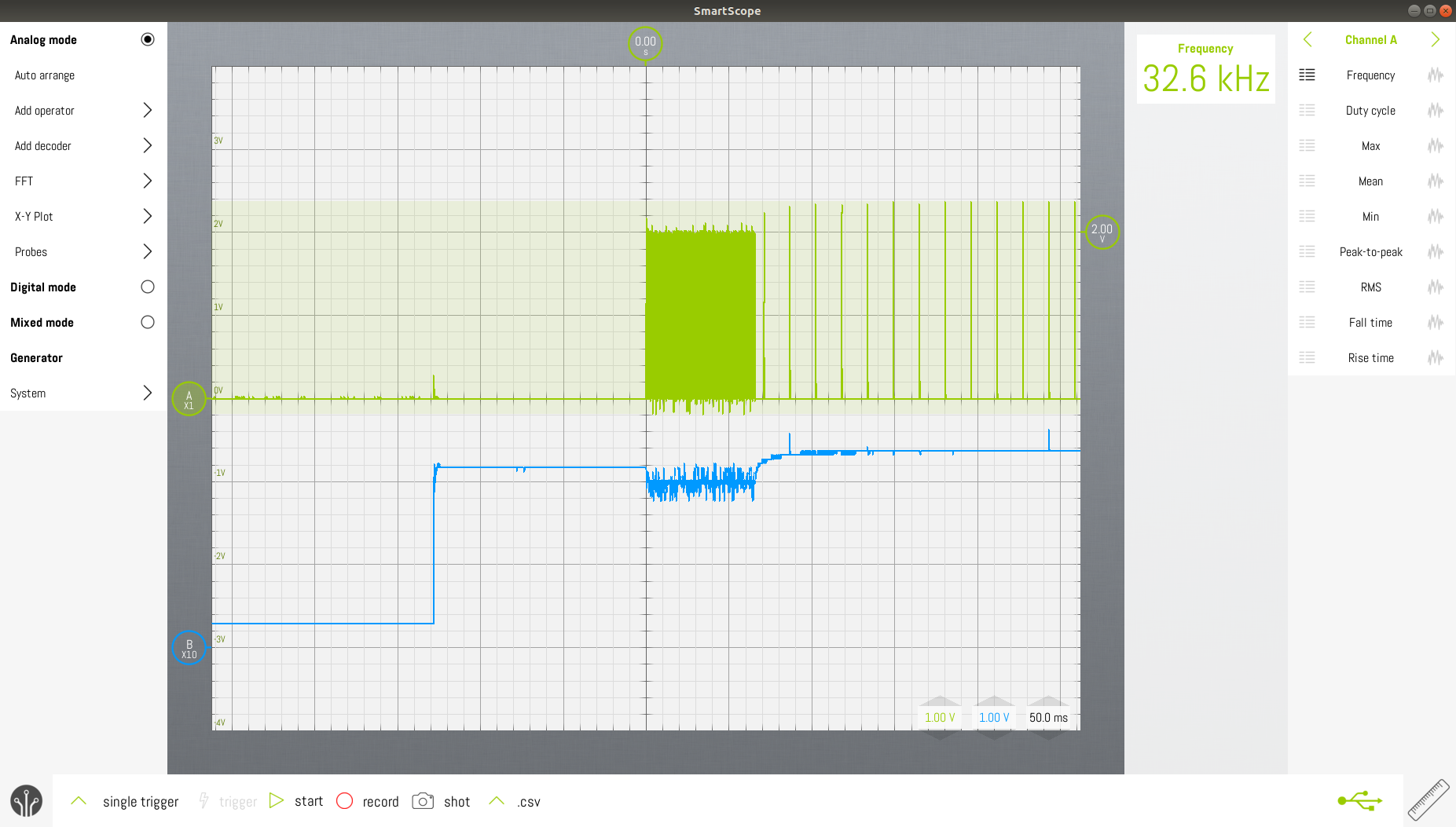
When connecting the battery, the LED flashes very brightly, as such wasting the energy we're trying to save so eagerly.
![]()
Green trace : Q output of monostable, blue is VCC of monostable Upon startup, the RV-3028, first outputs 32kHz pulses for about 65ms, only afterwards it creates the programmed 64Hz pulses. The monostable shouldn't drive the MOSFET as long as the pulse frequency is different from 64Hz.
This means that the monostable must be disabled during the first 250ms after power up.
It also means that the RTC must be always on. The flashing circuit must control an input of the one-shot timer.
Microcontrollers
The Attiny13A is the preferred part in the AVR-family. Attiny4 could have been possible as well.
ATTINY4 ATTINY13A Active @ 3V 32KHz : 15µA
100KHz : 50µA
1MHz : 280µA
8MHz : 1.2mA32KHz : 10µA
100KHz : 50µA
1MHz : 350µA
8MHz : 2mAIdle @ 3V
(PWM keeps running)32KHz : 1.8 to 2.1µA
100KHz : 5µA
1MHz : 40µA
8MHz : 300µAPower down @ 3V
WDT enabled5.5µA (@ -40°C) 5µA (@ -40°C) Power down @ 3V
WDT disabled25°C : 120nA
85°C : 310nA25°C : 130nA
85°C : 290nA- Remark that the ATTINY13A consumes less current when idle at 32KHz, than at power down with the WDT enabled.
- can be programmed with PlatformIO.
- The ATtiny13A, as well as ATtiny4 can't be clocked by a crystal. If operation on <100KHz is desired, an oscillator is needed. For 32.768KHz, the 2195-OM-7604-C7-32.768KHZ-20PPM-TA-QCCT-ND can be used. It consumes only 500nA. Of course, RV-3028 could be used for this purpose as well, which should save you some extra current.
When lower power is desired : PIC XLP : PIC16LF15313T-I/SN
- to be programmed with MPLAB, no open source solution
- 32KHz oscillator inside.
- max. 5.5µA in sleep mode, typically (25°C) : 0.78µA (measured 1.13µA)
- PWM can continue running in sleep mode if it runs from the internal 32KHz oscillator.
- #TritiLED : PIC12LF1571 @ 31kHz, running 2 PWM's while sleeping + monostable = only 2µA @ 3V.
Discrete implementation
I tried a few circuits, but with disappointing results. The current consumption, cost and PCB space is much higher than what would be expected when using an MCU.
Circuit 1
A classic schmitt trigger input inverter doesn't yield really low power. With a power supply of 2V, and a 10K resistor in series with GND and VCC leads yielded a current of about 25µA.
The SN74AUP1G14DBVT costs €0.61/pce, while an ATtiny13A only costs €0.52/pce and offers many times more functionality.
Circuit 2
Relaxation oscillator with low power comparator LPV7215. Hmm, it costs more than double the price of an ATtiny13A.
-
Off Topic : Reverse engineering Smart Superflash 317R rear light
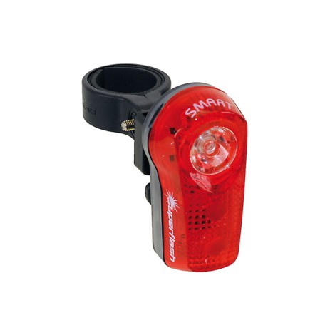
04/04/2020 at 15:40 • 0 commentsThis project log is a bit of a diversion. I had to repair this bike light, because the momentary switch started failing again.
![]()
Very bright and sturdy bike light, unfortunately protection to water ingress is not great. The contacts on the push button start to corrode, which makes it hard to turn the light on or off. Replacing the switch only temporarily solves the problem.
There are two red 5mm LEDs inside and a red SMD3535 LED. The Lumileds L135-A589003500000 might be a good replacement for the original 0.5W LED.
![]()
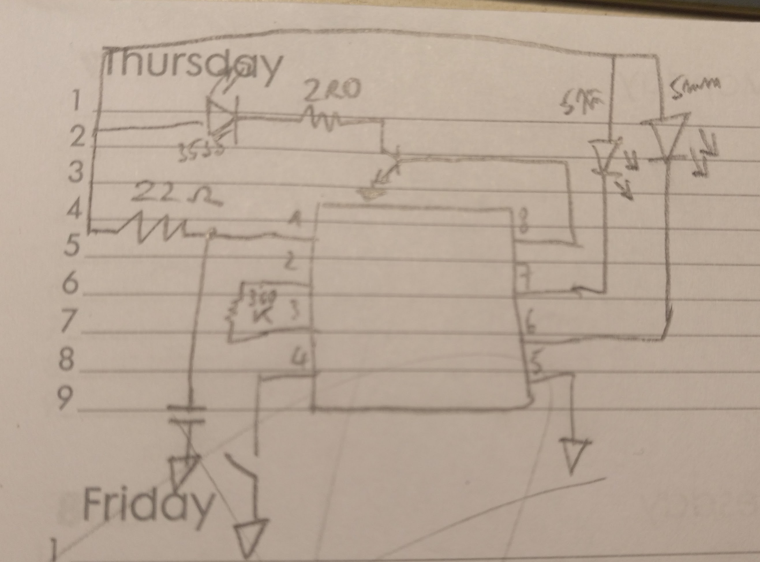
Quickly drawn schematic The controller is fed through an RC-filter, probably to prevent it from resetting when enabling the 3535 LED when the batteries are running out.
The 360K resistor determines the clock frequency of the controller. Pin 6, 7 and 8 control the LEDs. If you used a standard MCU, you would put a series resistor in any of these lines.
![]()
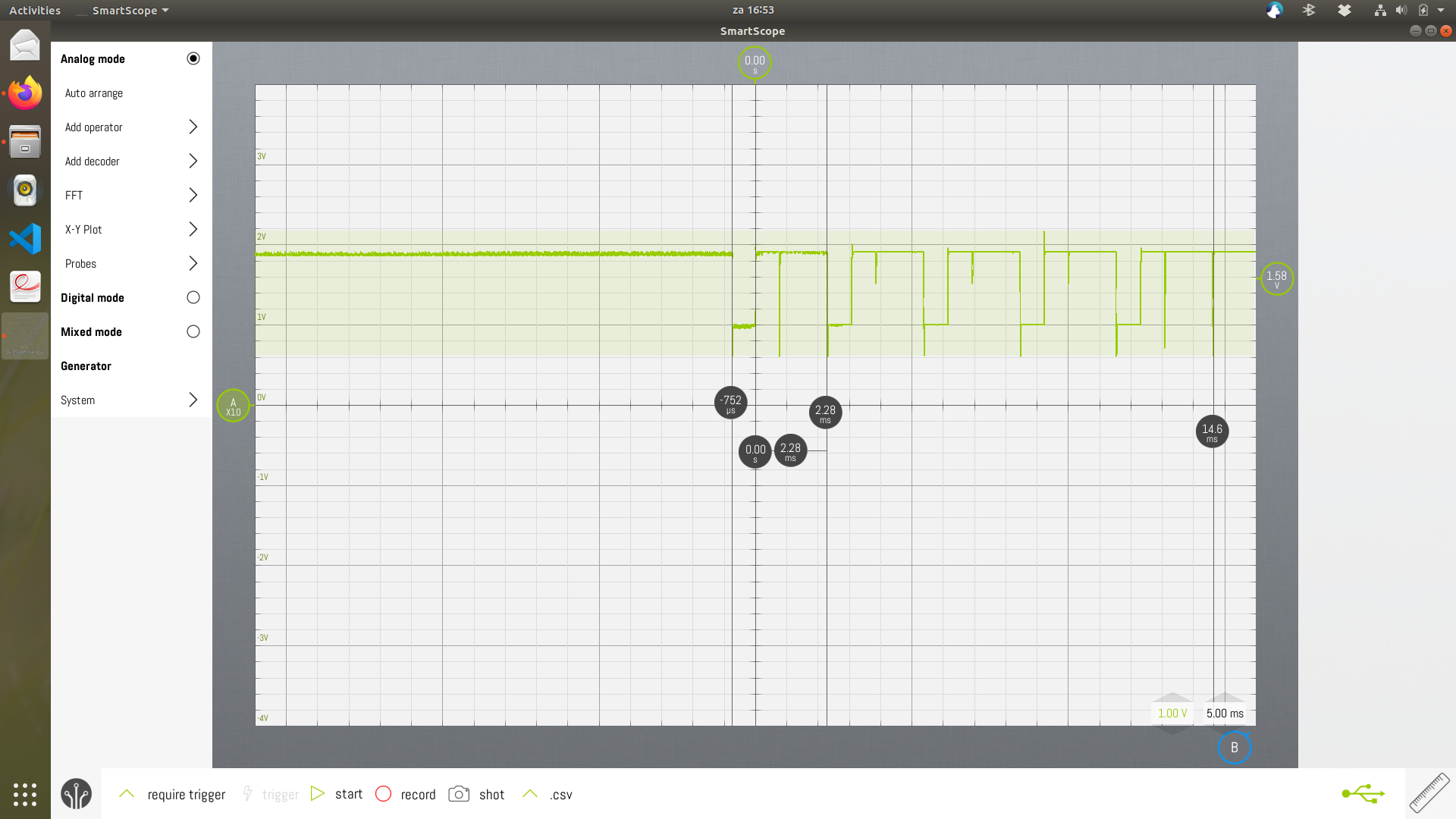
Blue : 3535 LED cathode, green : 5mm LED cathode The controller works in a six burst mode. During the first four bursts, only the 5mm LEDs are on, followed by two bursts where only the 3535 LED is on. A 6-burst cycle takes 745ms.
The 3535 LED burst is 30ms long.
![]()
Zooming in on the bursts on the cathode of the 3535 LED (blue trace). 125ms from the start of one burst to the start of the next one.
![]()
A burst on the 5mm LEDs consists of 5 pulses The two 5mm LEDs are on simultaneously. One pulse is 750µs ON, followed by 2.28ms OFF.
-
Housing
03/25/2020 at 21:07 • 0 commentsTic Tac® mint is delivered in a high quality container, unlike the old days. The box is cheap, and readily available. The box is currently made out of polypropylene (PP):
- translucent but not transparent
- PP floats on water
- good resistance to chemicals and bacterial growth
It's a shame to throw this wonderful box away once it served its original purpose. Let's upcycle!
![]()
Original casing with original contents In Belgium, Tic Tac® is delivered in at least two sizes : 49g and 16g. The 16g will be used here.
- Outer dimensions : 73.0 x 46.1 x 14.1 mm
- Maximum PCB dimensions : 65.5 x 40.0 x 11.0 mm
- Alternative PCB dimensions (will be fixed in lower part of the housing) : 40.0 x 42.4 x 11.0 mm
A few months later
![]()
Two of these tic-tac boxes are cracked because of accidentally stepping onto them. In the future I might use the little PP-spice boxes as sold by Delhaize. You can stand on them and they will not break. The lid comes off without the use of a screw driver. The label can also easily be removed. Outer dimensions : 84 x 50 x 21 mm
Another option would be to use the Woogie mints Tutti Frutti 16g box (Asalam Supermarkt Kortrijk). The PCB would have to be redesigned because the housing is quite small : 58 x 40 x 17 mm. This box also withstands the impact of an adult stepping onto it.
![]()
Ultra low power LED
<1.5µA current consumption when continuously on, optional flashing mode