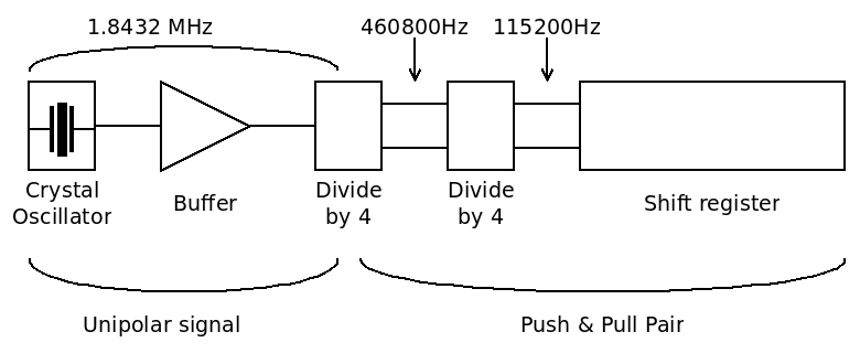
Supposing the whole shift register and the processor can sustain 115200bps, the clock generation looks like this :

It seems I can't find an oscillator slower than 1.8432MHz so I settle with that. I found an old large Xtal on eBay so the electronics will be deliciously weird. I'll use the circuit with 2 transistors shown atIt just works because it works indeed :-) However I have no idea of the impedance and other parameter of that laaarge crystal... I went through that study 4 years ago and logged everything so it will not be a serious problem.
The delicate part will be the buffer because my past experience with #Yet Another (Discrete) Clock shows that impedance matching is quite hard and even the 'scope can affect the very sensitive oscillator. Then that very weak signal must be amplified to a few milliamperes....
Then the signal goes through a modified unipolar div-by-4 cell. The input drives both PNP and NPN pass gates. The 2 outputs signals are then combined to create 2 non-overlapping pulses (code 01 and 10).
The non-overlapping pulses drive another NPN-only div-by-4. Again the outputs are combined into non-overlapping pulses to drive the shift register.
In theory it should work, right ?
Why do I use "div-by-4" cells instead of "div-by-2" ?
There is no disadvantage to this choice, but a few notable advantages, in particular for the type of cells I use.
Complexity-wise, dividing by 4 or twice by 2 is the same : same number of parts (roughly) but the output is 2× slower, so it's better, and easier to turn into a pair of "non-overlapping signals" thanks to a pair of transistors in ANDN configuration.
 Yann Guidon / YGDES
Discussions
Become a Hackaday.io Member
Create an account to leave a comment. Already have an account? Log In.