 Paul Gould
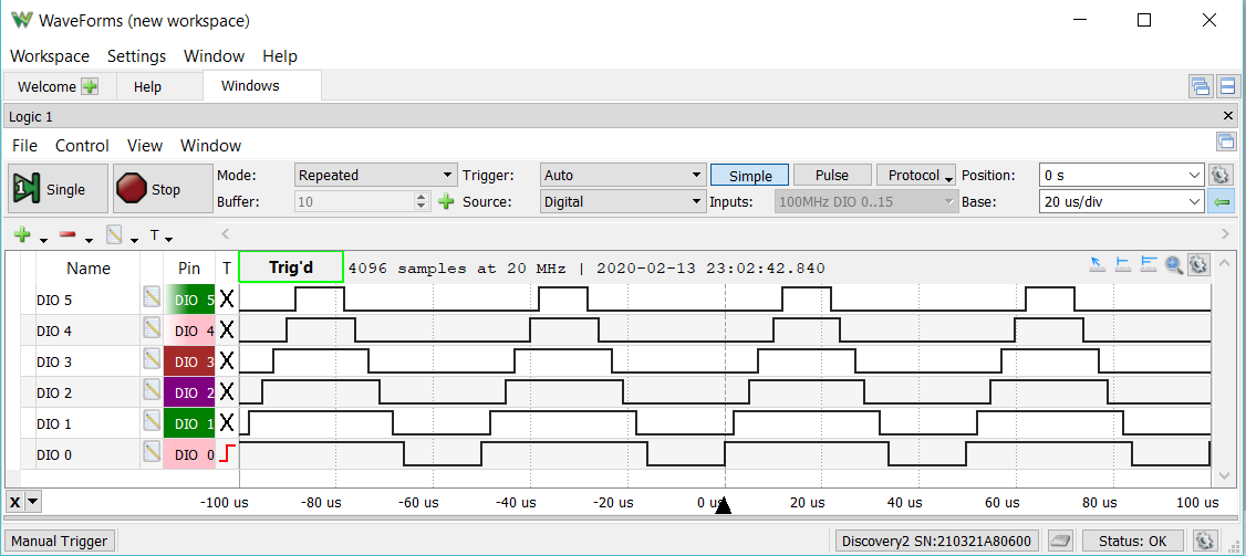
Starting point for Brushless motor control is the get the required features up and running. The ESP-32 has a MCPWM (Motor Control) hardware block. The hardest part was getting the "centre aligned" working with the many different types of sync function. The one I needed was missing from the header file.
mcpwm.h for the ESP32 is missing some enums
edit
MCPWM_SELECT_SYNC_OFF, /*!< SYNC is off*/
was missing a comma
/**
 * @brief MCPWM select sync signal input
 */
typedef enum {
    MCPWM_SELECT_SYNC_OFF,          /*!< SYNC is off*/
    MCPWM_SELECT_SYNC_INT0,        /*!<Select SYNC0 as internal*/
    MCPWM_SELECT_SYNC_INT1,        /*!<Select SYNC1 as internal*/
    MCPWM_SELECT_SYNC_INT2,        /*!<Select SYNC2 as internal*/
    MCPWM_SELECT_SYNC0,            /*!<Select SYNC0 as input*/
    MCPWM_SELECT_SYNC1,            /*!<Select SYNC1 as input*/
    MCPWM_SELECT_SYNC2,            /*!<Select SYNC2 as input*/
} mcpwm_sync_signal_t;
The online file is located at
I have issued a bug fix request.
Arduino ino file
#include "driver/mcpwm.h"
#include "soc/mcpwm_reg.h"
#include "soc/mcpwm_struct.h"

// MCPWM Pins
#define GPIO_PWM0A_OUT 15   //Set GPIO 15 as PWM0A
#define GPIO_PWM0B_OUT 02   //Set GPIO 02 as PWM0B
#define GPIO_PWM1A_OUT 00   //Set GPIO 00 as PWM1A
#define GPIO_PWM1B_OUT 04   //Set GPIO 04 as PWM1B
#define GPIO_PWM2A_OUT 16   //Set GPIO 16 as PWM2A
#define GPIO_PWM2B_OUT 17   //Set GPIO 17 as PWM2B

static void setup_mcpwm_pins()
{
    Serial.println("initializing mcpwm control gpio...n");
    mcpwm_gpio_init(MCPWM_UNIT_0, MCPWM0A, GPIO_PWM0A_OUT);
    mcpwm_gpio_init(MCPWM_UNIT_0, MCPWM0B, GPIO_PWM0B_OUT);
    mcpwm_gpio_init(MCPWM_UNIT_0, MCPWM1A, GPIO_PWM1A_OUT);
    mcpwm_gpio_init(MCPWM_UNIT_0, MCPWM1B, GPIO_PWM1B_OUT);
    mcpwm_gpio_init(MCPWM_UNIT_0, MCPWM2A, GPIO_PWM2A_OUT);
    mcpwm_gpio_init(MCPWM_UNIT_0, MCPWM2B, GPIO_PWM2B_OUT);
} // setup_pins()

static void setup_mcpwm()
{
   setup_mcpwm_pins();

   mcpwm_config_t pwm_config;
   pwm_config.frequency = 40000;  //frequency = 20000Hz
   pwm_config.cmpr_a = 50.0;      //duty cycle of PWMxA = 50.0%
   pwm_config.cmpr_b = 50.0;      //duty cycle of PWMxB = 50.0%
   pwm_config.counter_mode = MCPWM_UP_DOWN_COUNTER; // Up-down counter (triangle wave)
   pwm_config.duty_mode = MCPWM_DUTY_MODE_0; // Active HIGH
   mcpwm_init(MCPWM_UNIT_0, MCPWM_TIMER_0, &pwm_config);    //Configure PWM0A & PWM0B with above settings
   mcpwm_init(MCPWM_UNIT_0, MCPWM_TIMER_1, &pwm_config);    //Configure PWM0A & PWM0B with above settings
   mcpwm_init(MCPWM_UNIT_0, MCPWM_TIMER_2, &pwm_config);    //Configure PWM0A & PWM0B with above settings

   mcpwm_sync_enable(MCPWM_UNIT_0, MCPWM_TIMER_0, MCPWM_SELECT_SYNC_OUT0, 0);
   mcpwm_sync_enable(MCPWM_UNIT_0, MCPWM_TIMER_1, MCPWM_SELECT_SYNC_OUT0, 0);
   mcpwm_sync_enable(MCPWM_UNIT_0, MCPWM_TIMER_2, MCPWM_SELECT_SYNC_OUT0, 0);

   MCPWM0.timer[0].sync.out_sel = 1;
   delayMicroseconds(100);
   MCPWM0.timer[0].sync.out_sel = 0;

   mcpwm_set_duty(MCPWM_UNIT_0, MCPWM_TIMER_0, MCPWM_OPR_A, 70);
   mcpwm_set_duty(MCPWM_UNIT_0, MCPWM_TIMER_0, MCPWM_OPR_B, 60);
   mcpwm_set_duty(MCPWM_UNIT_0, MCPWM_TIMER_1, MCPWM_OPR_A, 50);
   mcpwm_set_duty(MCPWM_UNIT_0, MCPWM_TIMER_1, MCPWM_OPR_B, 40);
   mcpwm_set_duty(MCPWM_UNIT_0, MCPWM_TIMER_2, MCPWM_OPR_A, 30);
   mcpwm_set_duty(MCPWM_UNIT_0, MCPWM_TIMER_2, MCPWM_OPR_B, 20);
} // setup_mcpwm

void setup()
{
   Serial.begin(115200);
   Serial.println( "Start ");
   setup_mcpwm();
} // setup()

void loop()
{
   Serial.println("D");
   delay(500);
} // loop()
I will have to look at dead-time next, so I only have to set three PWM values instead of six.
I could also save some pins and use the DRV8305 internal dead time feature.
Discussions
Become a Hackaday.io Member
Create an account to leave a comment. Already have an account? Log In.