-
13d Print the parts
The list of parts you need to print (don't forget to use filaments that are UV stable, I printed with PETG from Prusa). I used a Prusa MK3, a few notes on my settings - 5 bottom layers, 7 top layers, fan always on, 0.15 layer height on all components.
2 Wheels - 20-25% infill should be enough
2 Wheel motor mounts - if you don't find any metallic options. I bought my motors with mounts and I used those, but had the 3d mounts designed already.
1 Vertical motor mount - use the most rigid filament you have, 15-20% infill
Printed with Flexfill 98A:
Cutter mount ( 2 part) - 20-25% infill
-
2Plexi
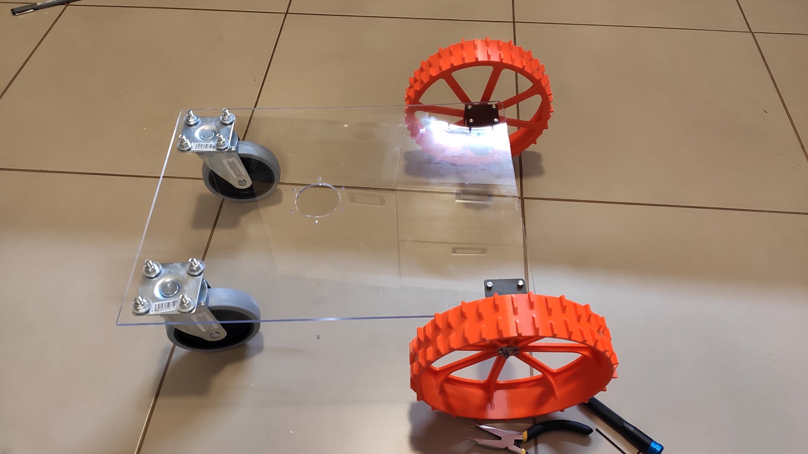
Get a plexiglass sheet of 4-5mm thick. Cut a piece of 40cm by 30 cm. (You can use whatever you have handy but will have to adjust the instructions for thickness) Try to cut it as square as possible.
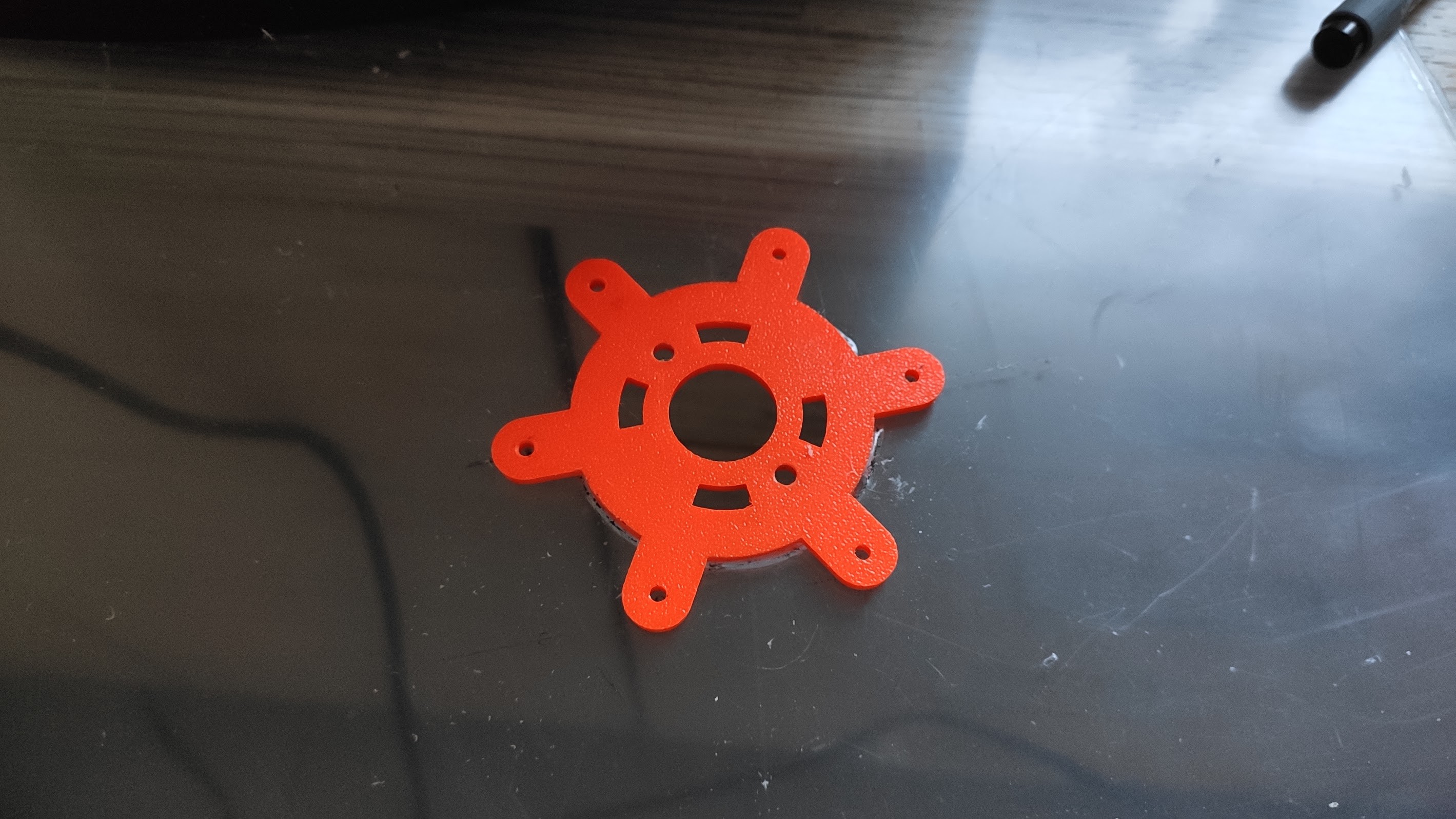
Use the 3D printed vertical motor mount to draw the template for cutting the hole to mount it.
First decide on the placement of the cutting teeth, make sure they don't interfere with the front or rear wheels. When you'r happy with approximative placement, draw a line from left to right on the board, make sure it is perpendicular, and sketch and X at 15cm (given the width of the robot is 30cm). Place the motor mount with the flat side down , align the screw holes on the line, and draw the outlines of the circle that needs to be cut.
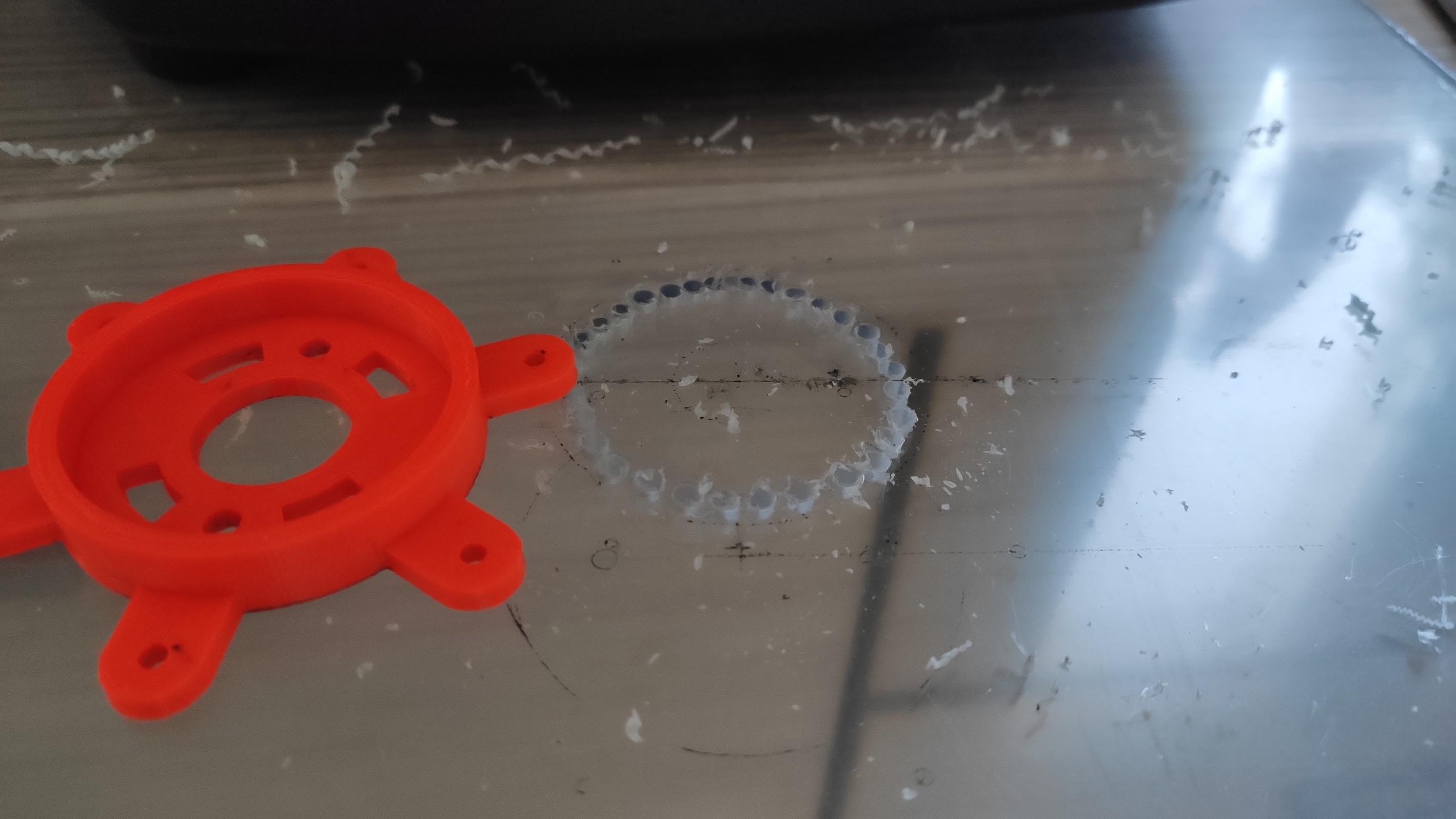
Use 3mm drill bits to drill holes around the perimeter, make sure to have enough clearing space. Also try to place them as close to each other as possible. Use 5-6 mm drill bits to enlarge the holes.
![]()
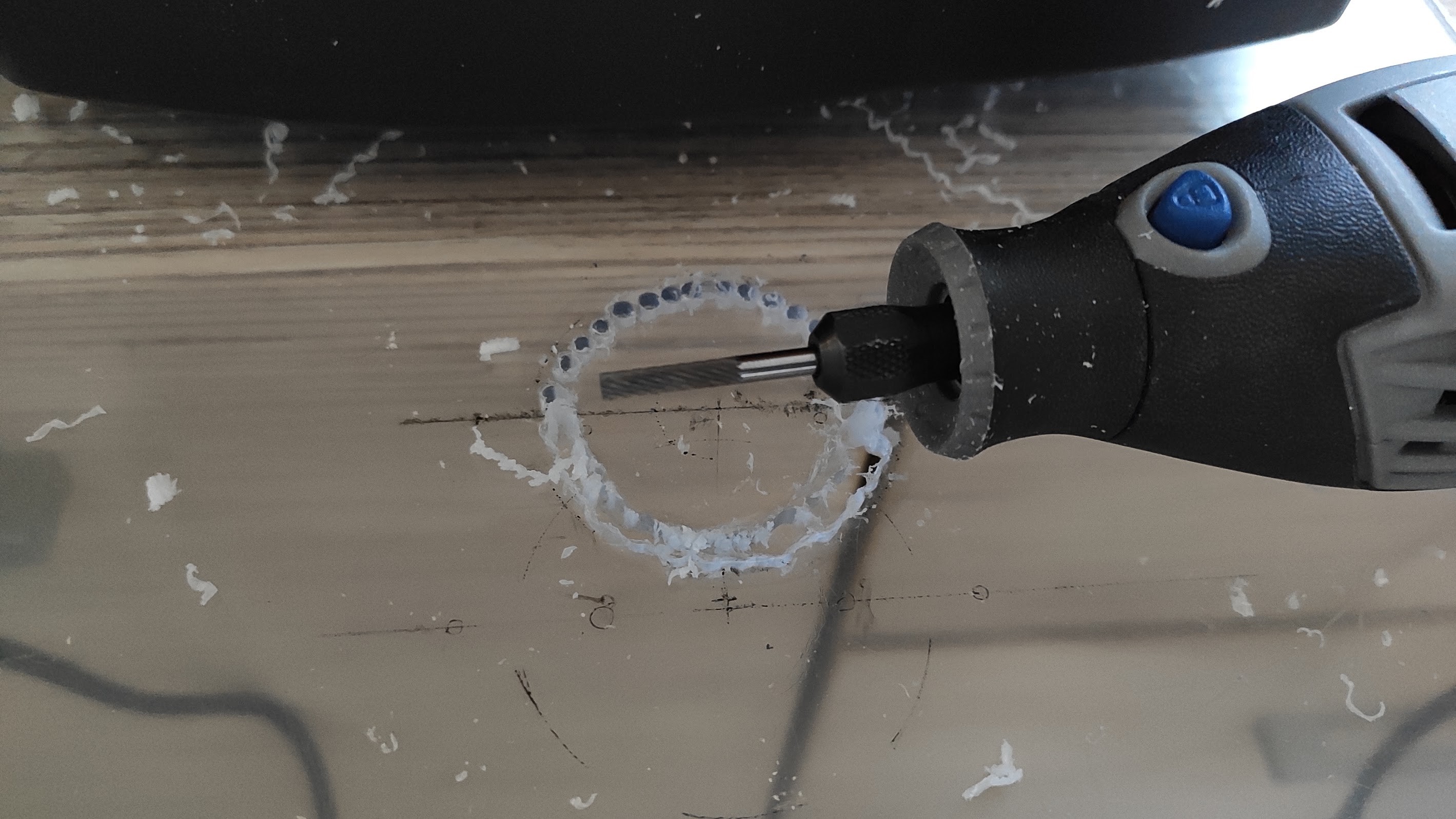
Use a Dremel with a cutting drill bit to cut the inner circle first:
![]()
![]()
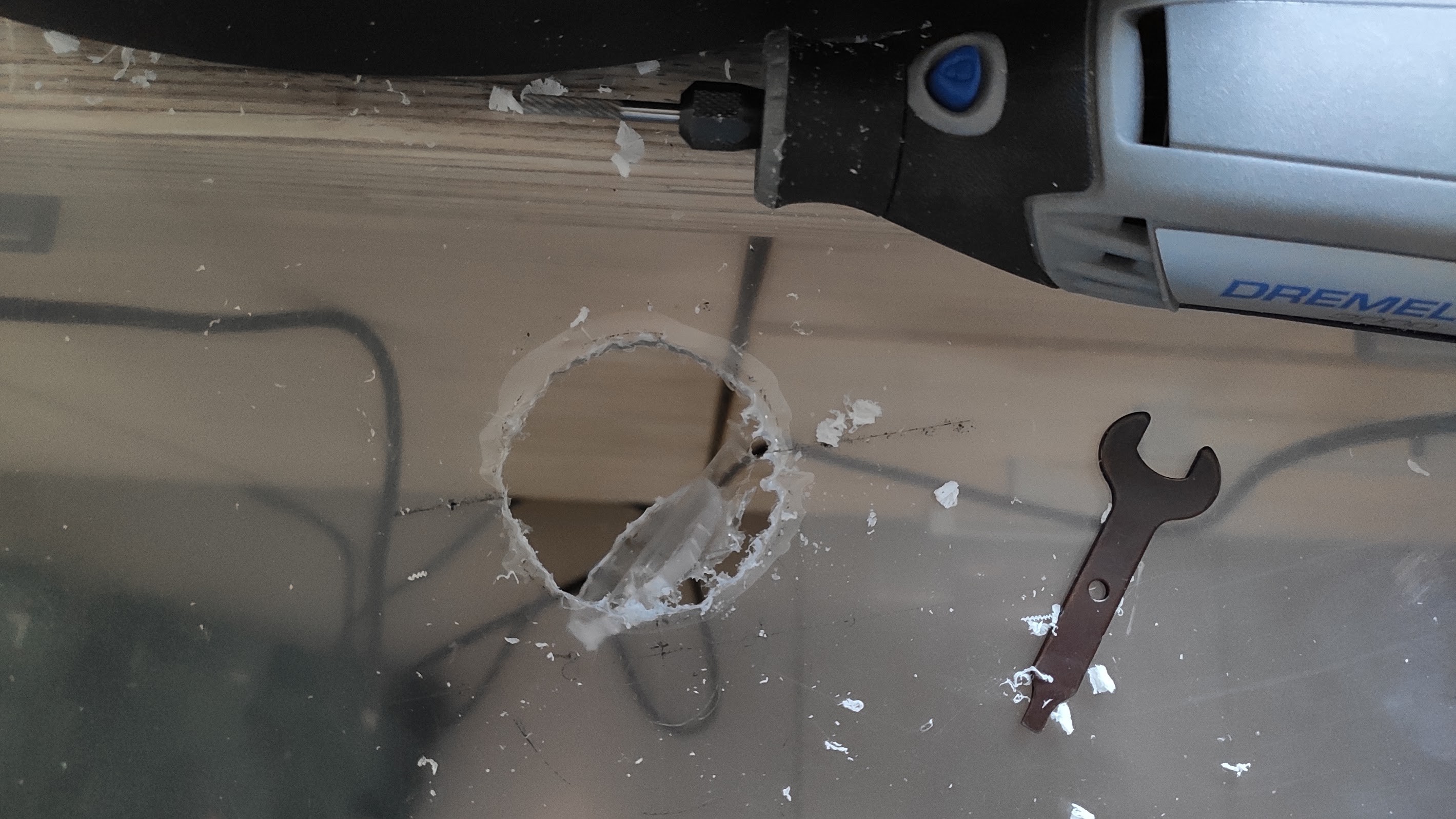
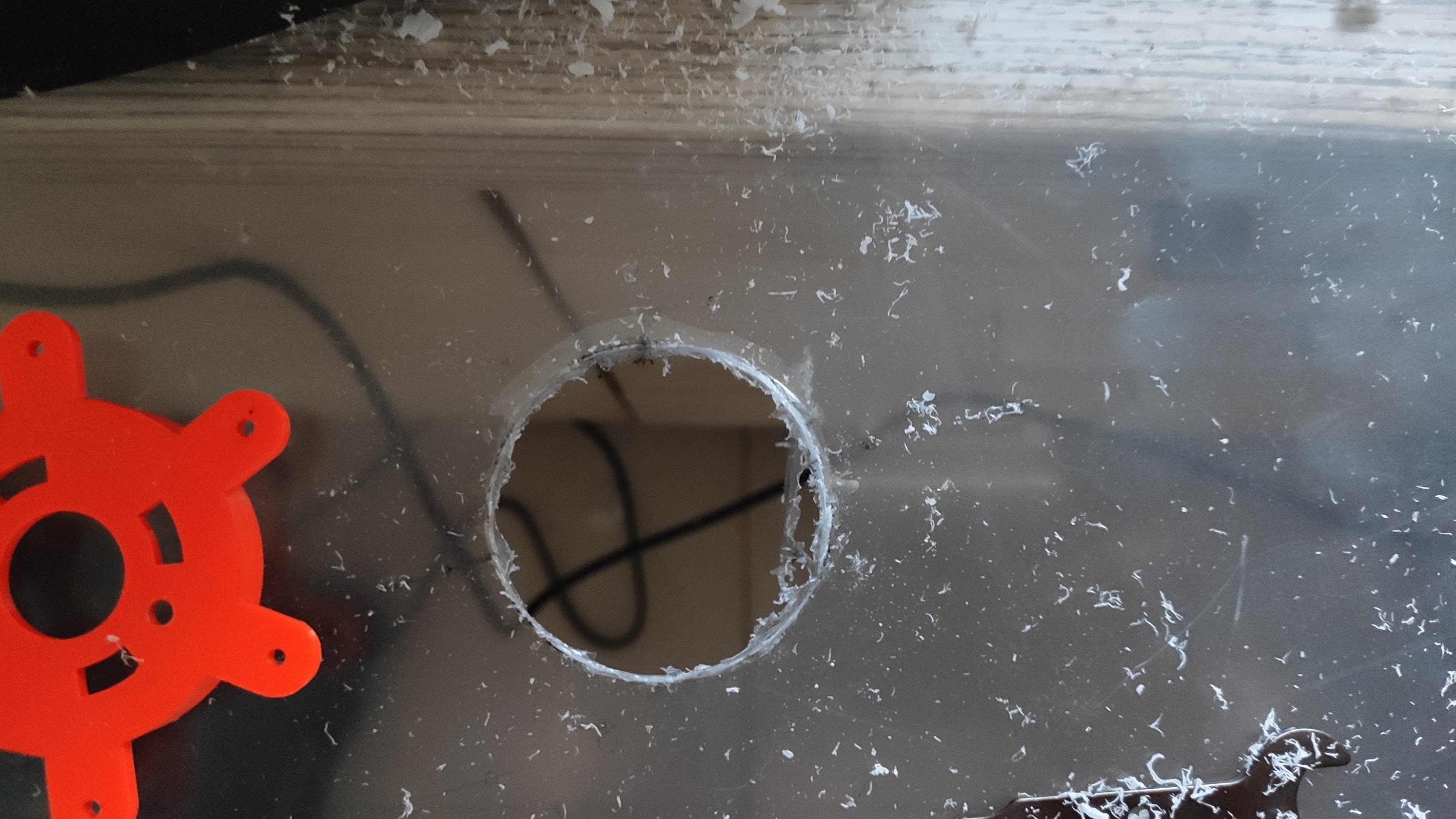
Enlarge and finish the circle to fit the vertical motor mount. Use two hands when holding the Dremel for better stability.
![]()
![]()
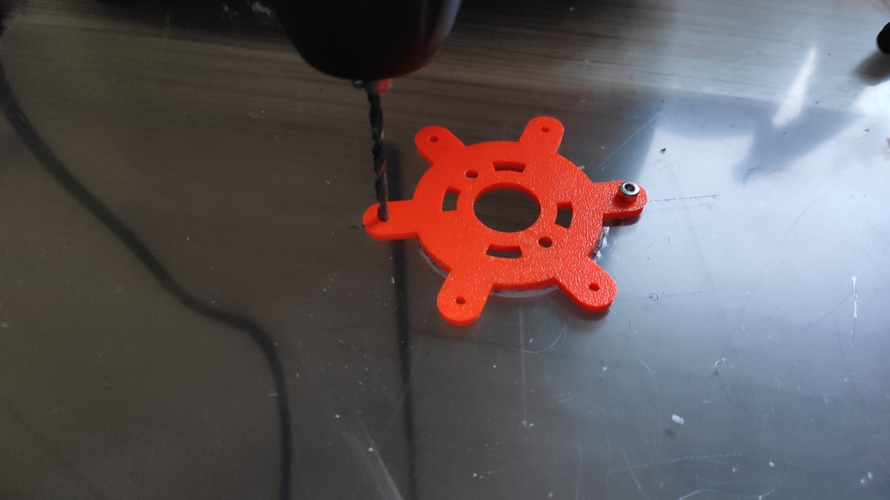
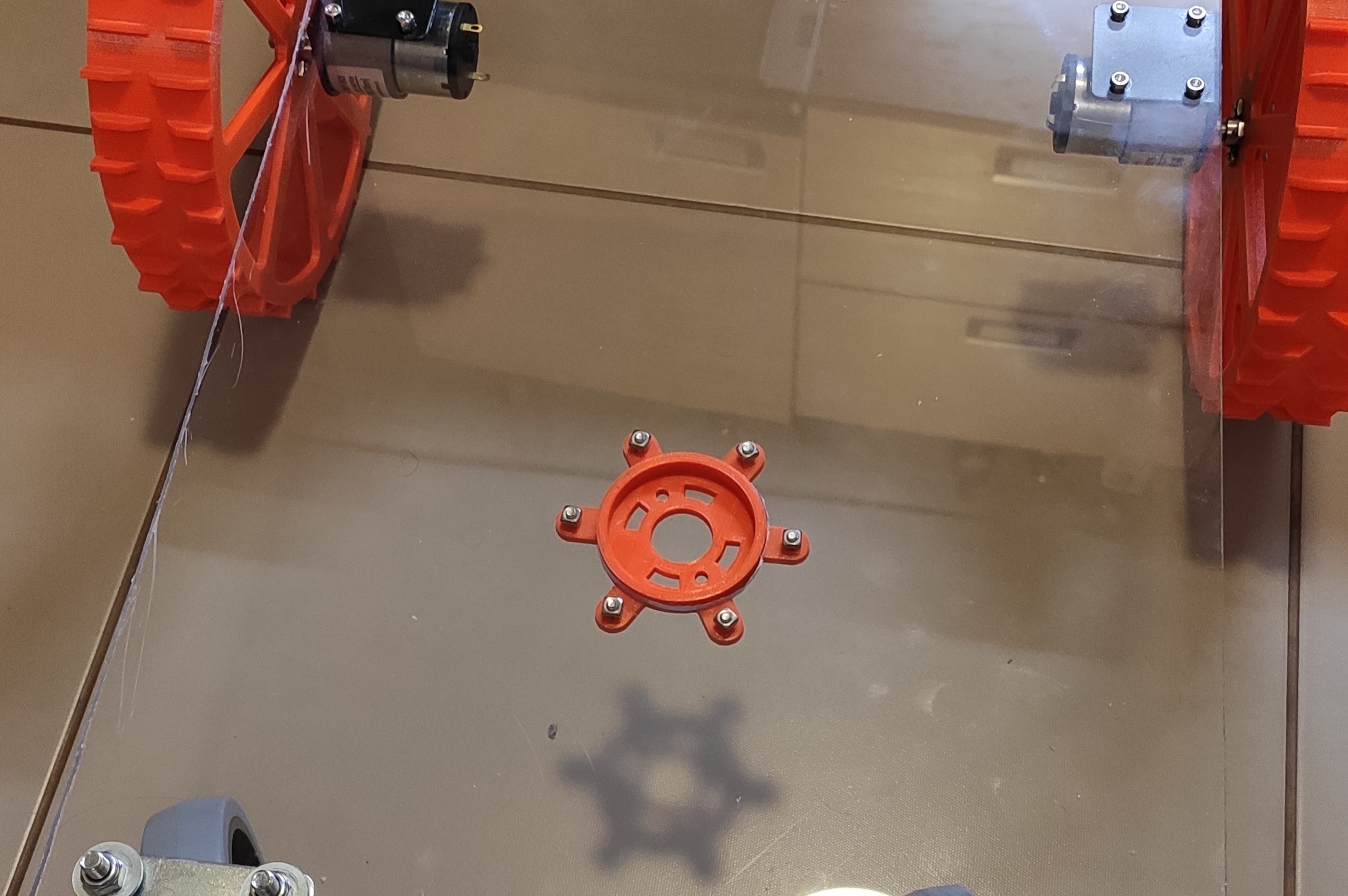
Holding the mount tight, drill one hole for mounting using a 3mm bit, and then put a screw in and tighten it before drilling the rest of the holes:
![]()
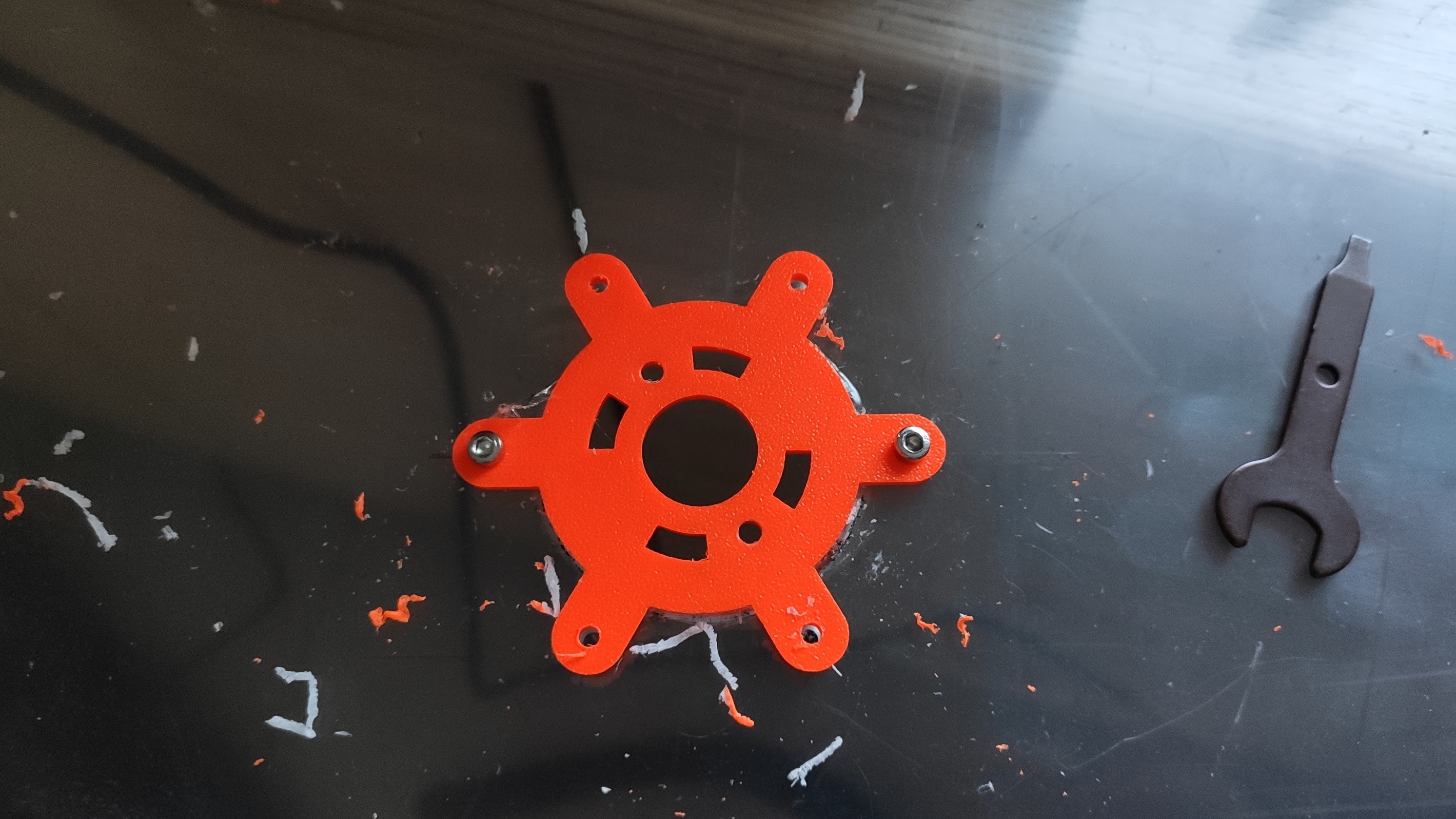
Also put a screw in the second hole and tighten it. Drill the rest of the holes.
![]()
It's time to drill the holes for the swivel wheels and rear wheel motors.
Use your best judgement. Try to space all of them as far away as possible from each other, but leave about 0.5-1cm of space from the border for the swivel wheels. The motor mounts should be flush with the side border.
Plexiglass drilling tips:
- if you are using plexiglass and need a large diameter hole, first drill a smaller one (half size) and then the bigger one.
- drill with the smallest speed possible. When drilling fast it gets hot and starts to melt which blocks the drill. Use a electric screwdriver for that.
-
3Swivel wheels
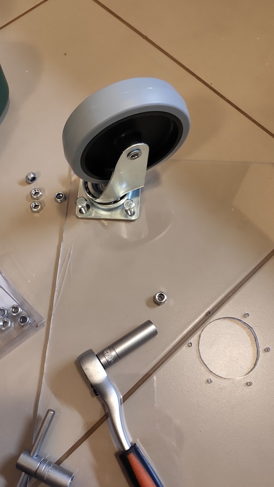
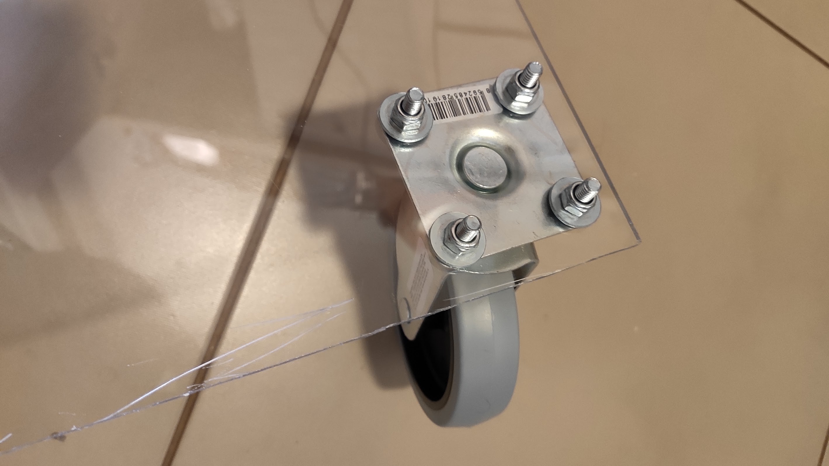
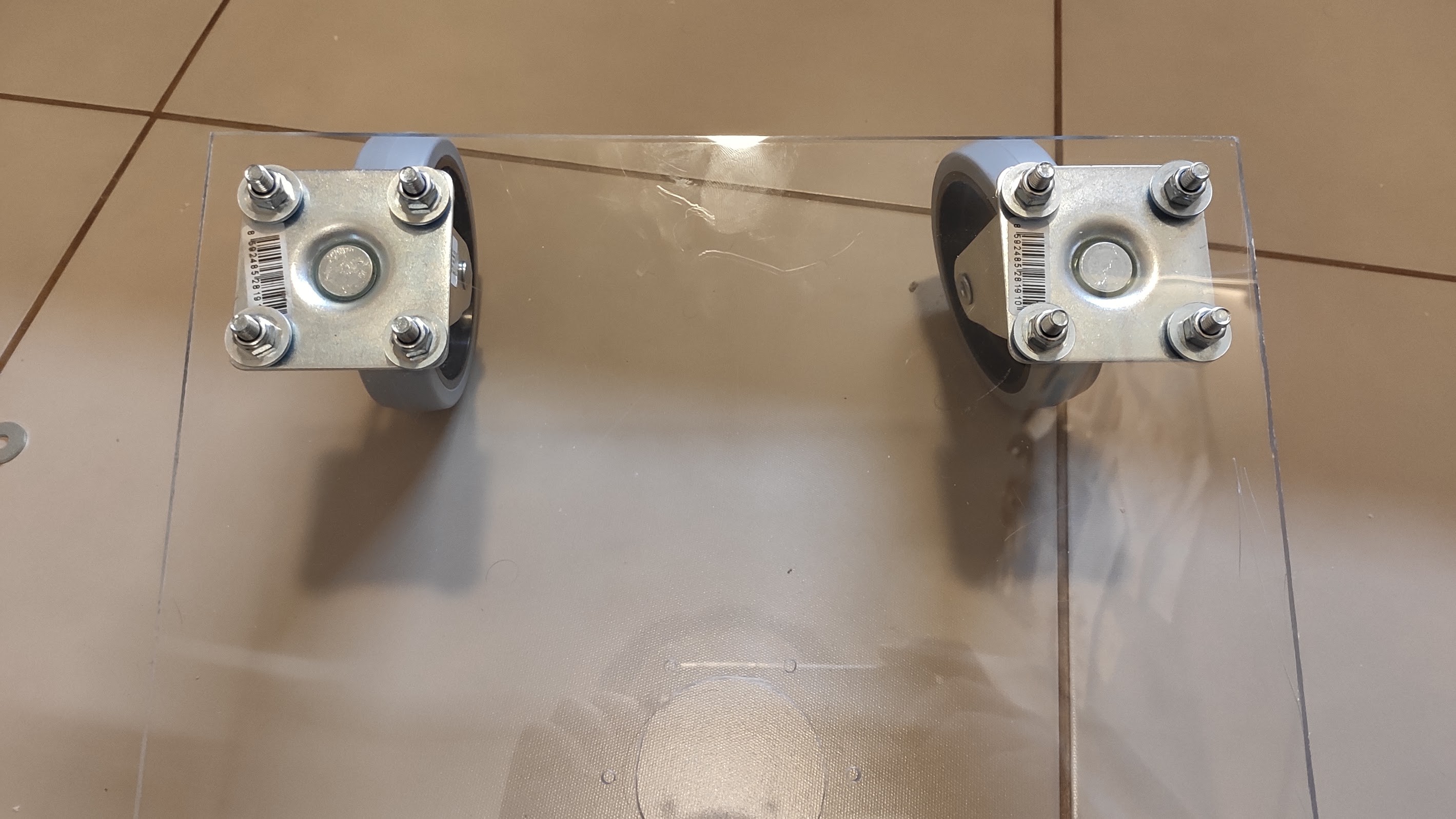
Mount the swivel wheels. Use your best judgement. It all depends on what you find in stores. Mine are fixed with M6 screws:
![]()
![]()
![]()
WARNING: don't tighten the screws too much, the metal part might not be perfectly flat, and will cause the plexi to bend and crack (that's what happened to me, but I noticed only the next day).
-
4Rear wheels
This step again depends on what motor mounts you are using.
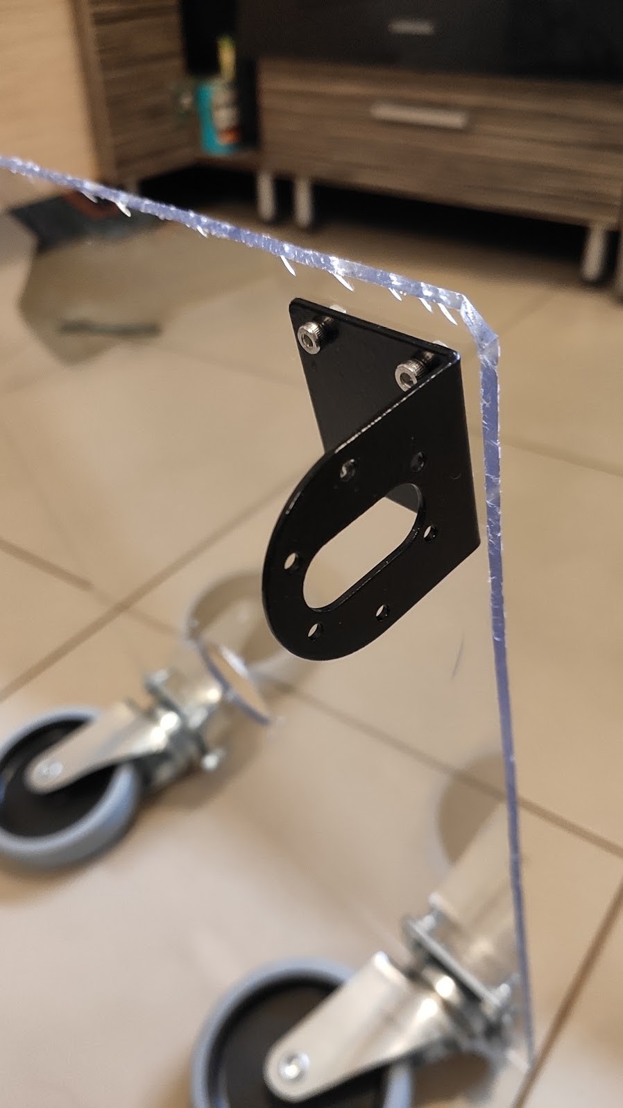
Make sure they are flush with the board border (not like in the picture, as my cut wasn't straight and I tried to compensate):
![]()
Keep a small offset from the rear of the board (about 1cm).
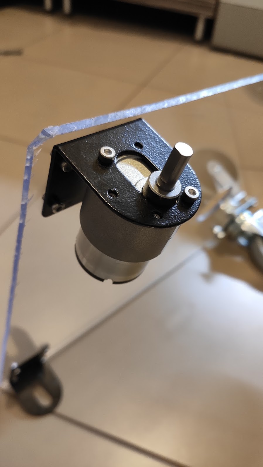
Mount the motors:
![]()
In my case two screws were enough. You need really short screws!!
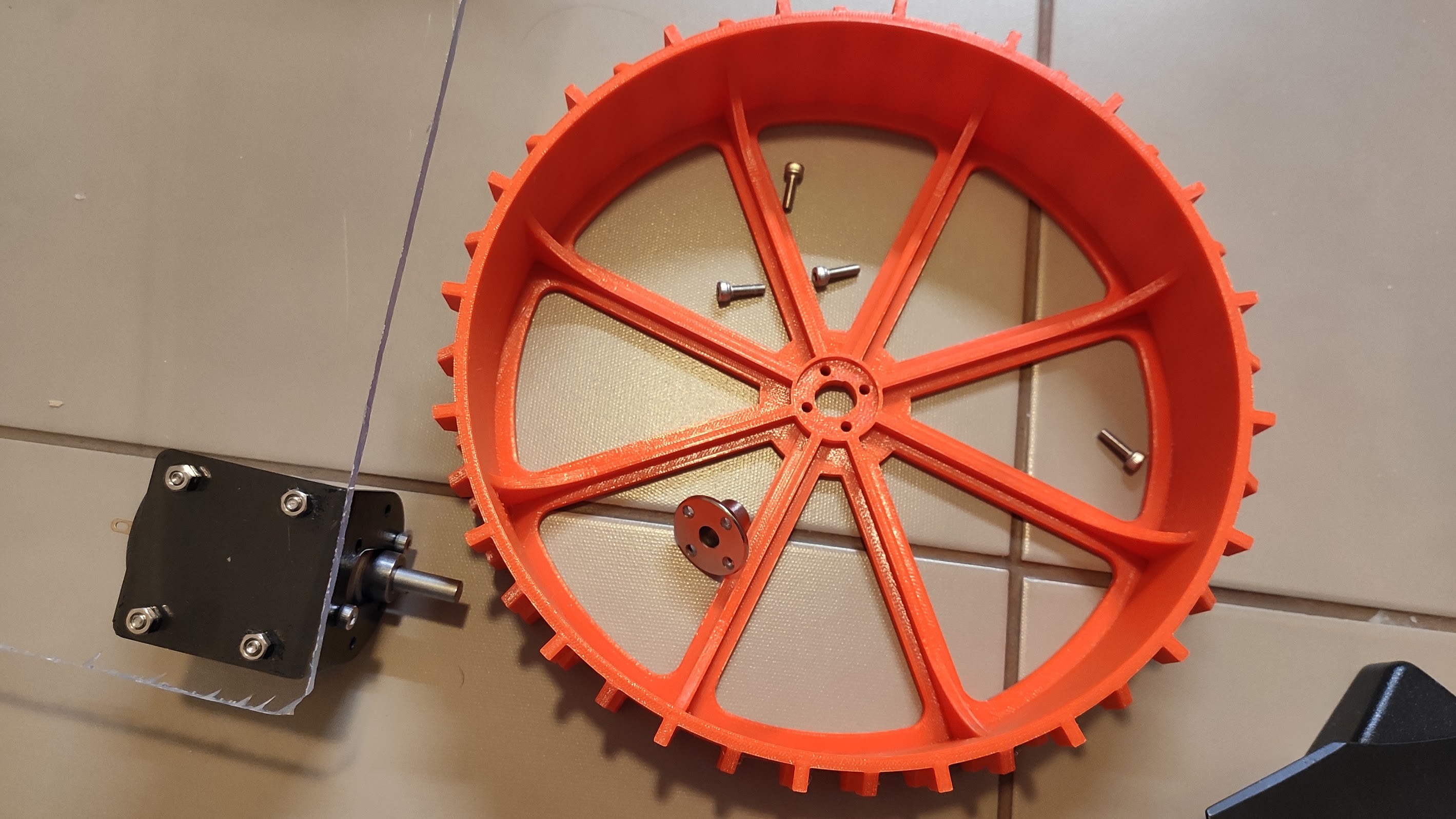
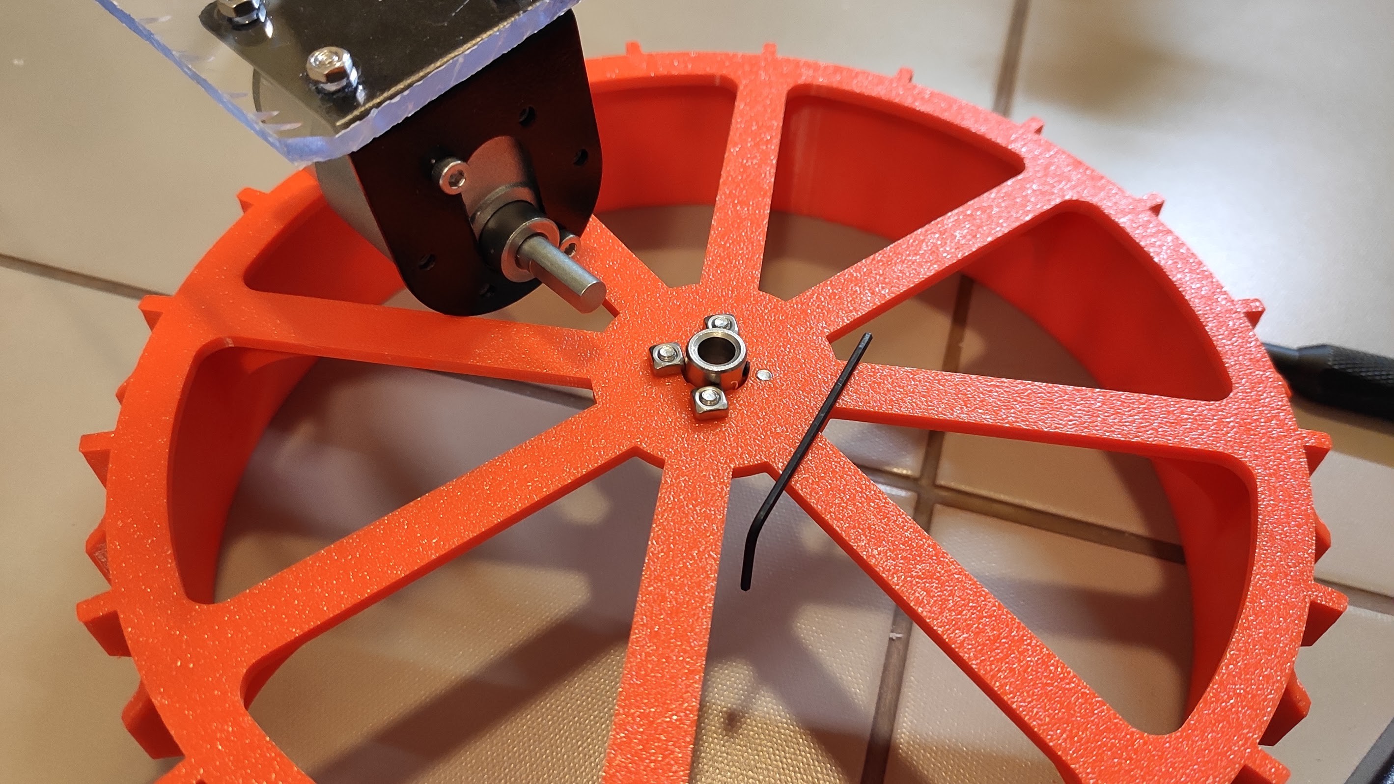
For the Wheels you need 4 M3 10mm screws, and 4 M3 square nuts - this is so they block in the flange shaft mount.
![]()
![]()
Note the one screw which wasn't fastened because it would block the shaft fastening screw (the black one in the next picture).
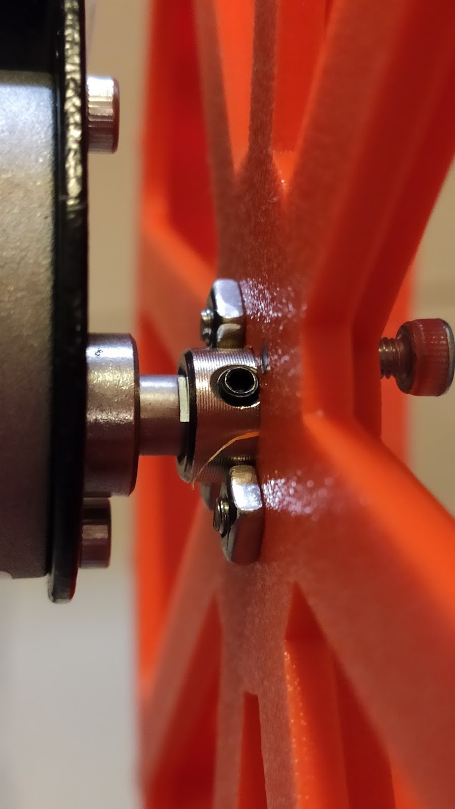
Tighten the screw for fixing the flange to the shaft of the motor:
![]()
Now with the help of pliers try to fasten the 4th nut and screw together.
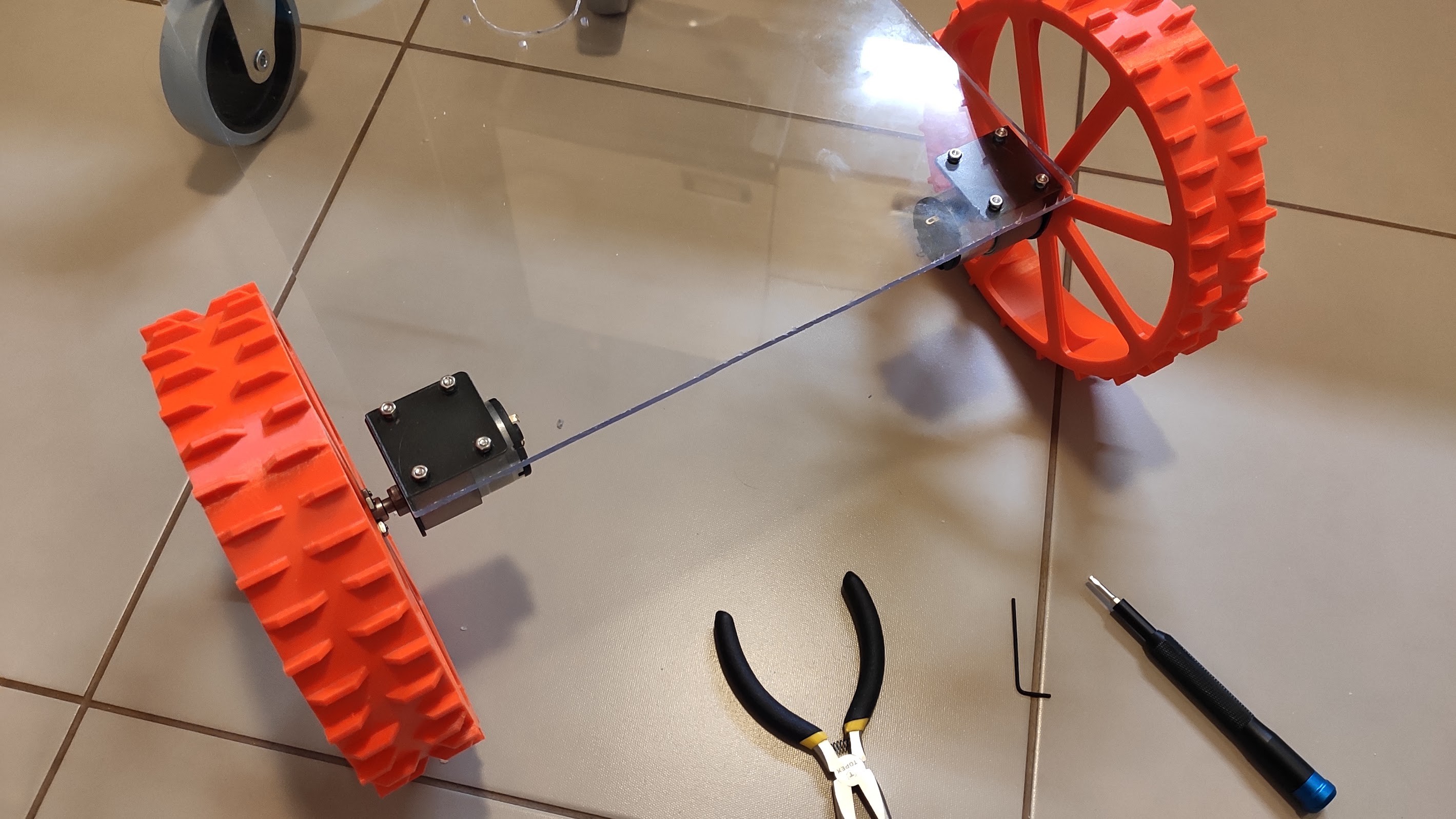
And the end-result:
![]()
![]()
-
5Mounting vertical motor
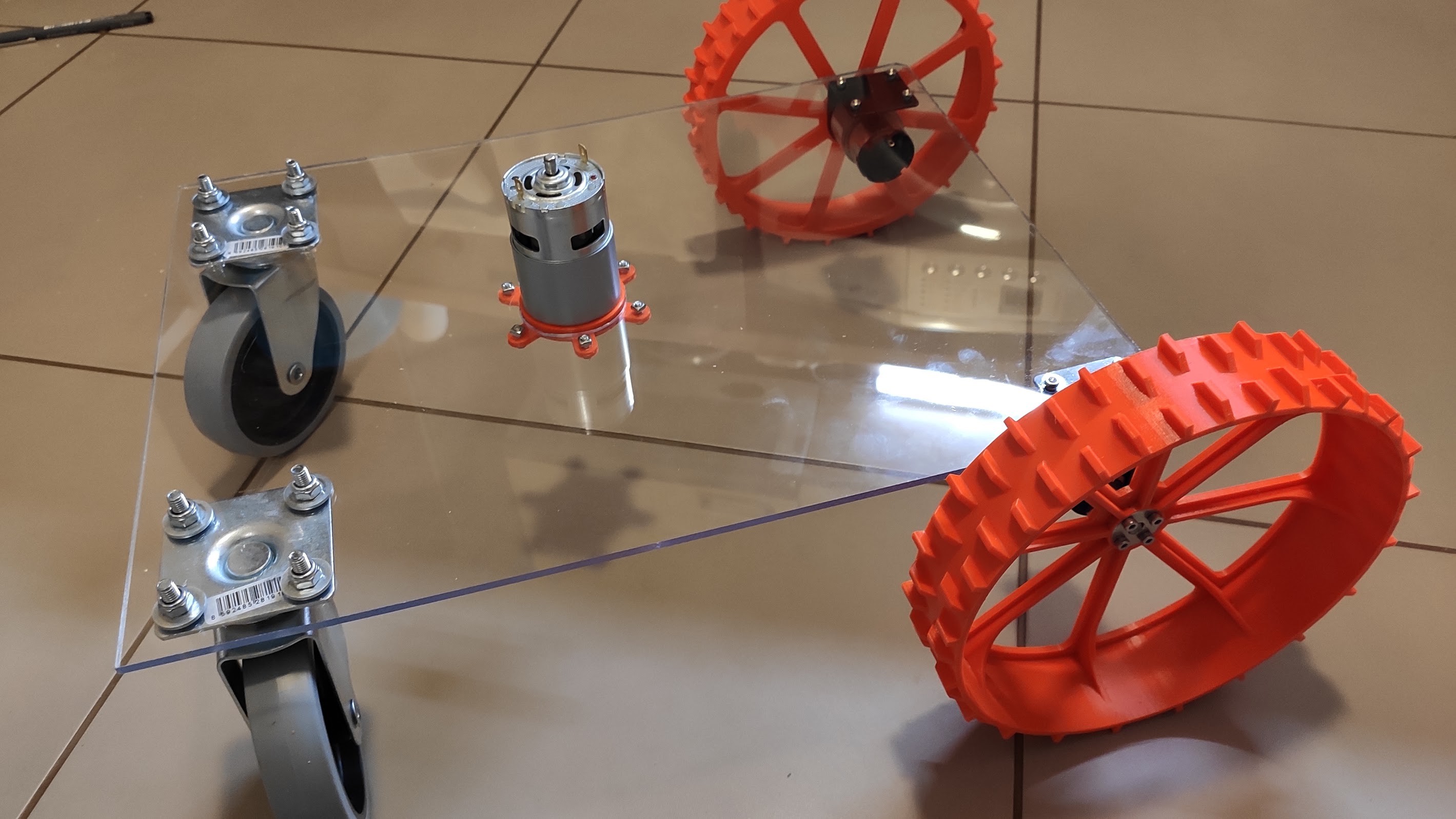
Fasten the motor mount, inserting it from the underneath. Use whatever M3 screws and nuts you have handy. I used square nuts as I ran out of hexagonal ones, but it's much harder to tighten these. I'll replace them when I manage to get new ones.
![]()
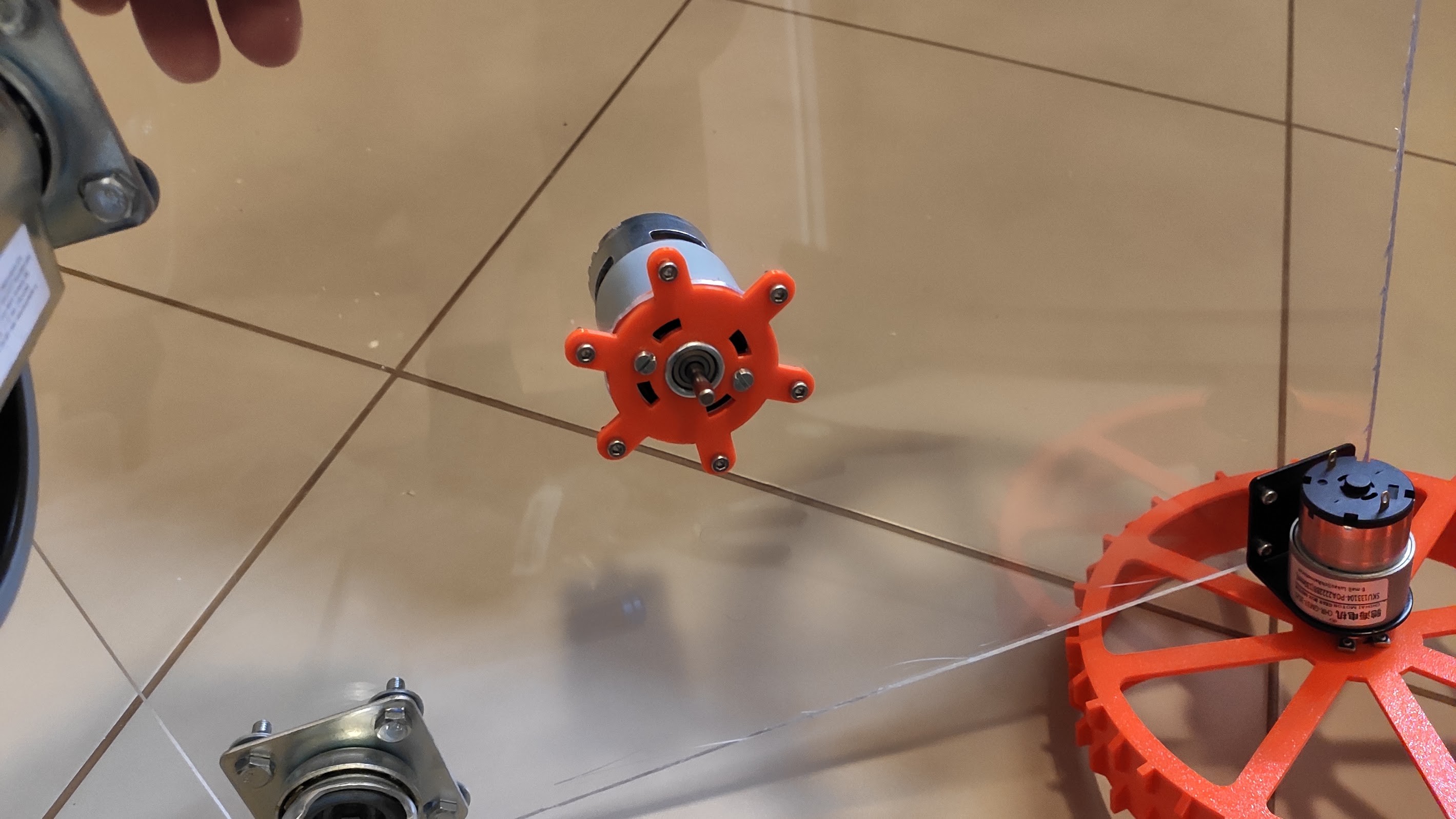
Mount motor atop and fasten it with two short M4 screws (otherwise they will destroy your motor, check that they don't interfere ):
![]()
![]()
-
6Power wires
We are going to add a power meter so we can predict the required battery capacity for a decent autonomy.
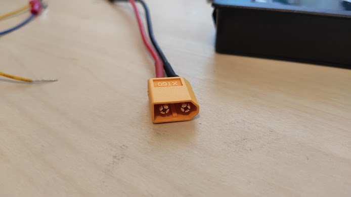
The most common battery connector is a XT60 and that's what I'm using for the build.
![]()
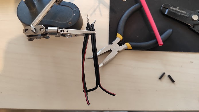
Cut two, about 15cm wires, and strip them. On one side strip both wires to 10mm. Cross them positive to positive, negative to negative as in the picture:
![]()
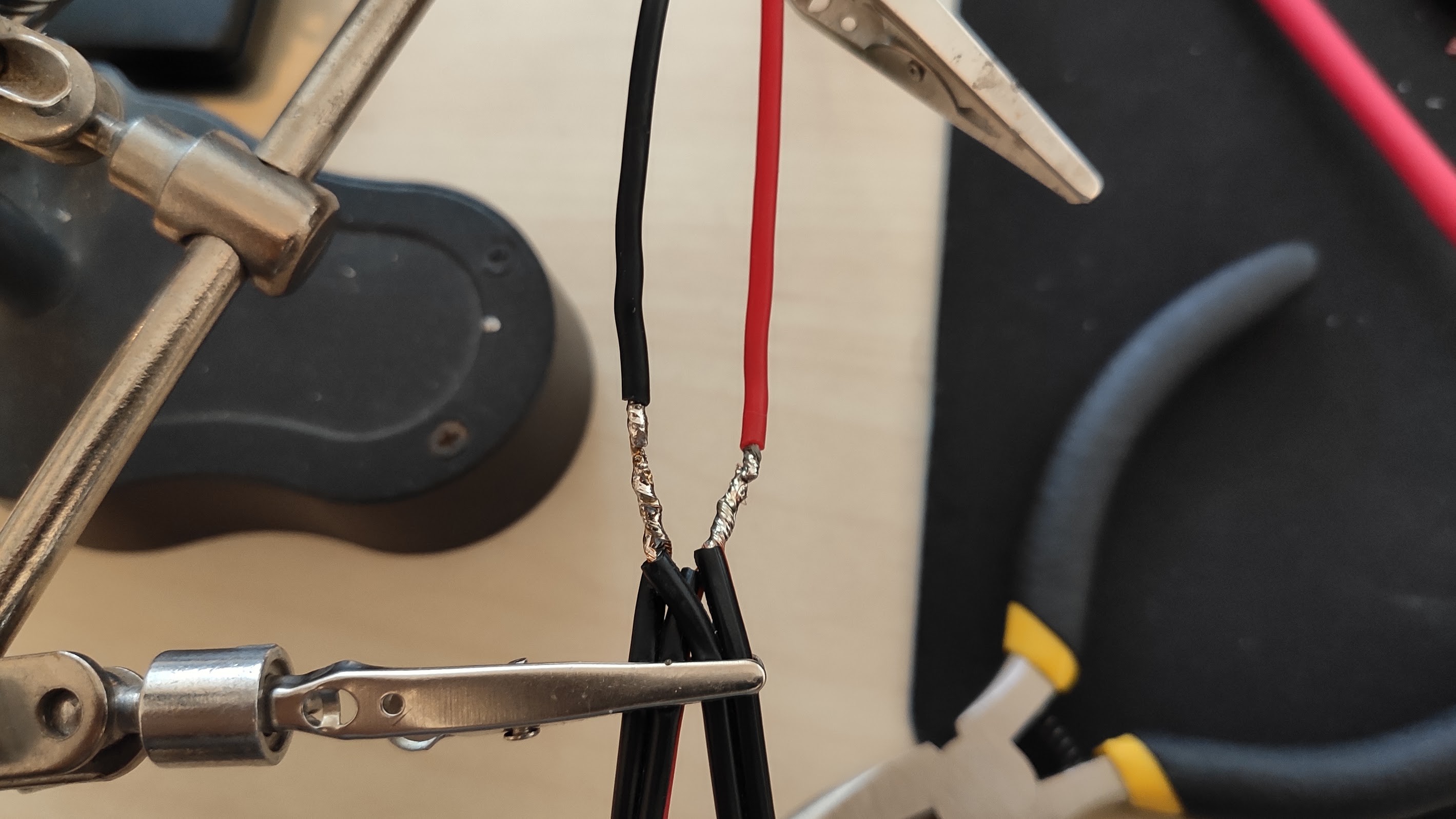
Put flux on, heat them, then put solder just enough so it sucks all the solder in, plus just a bit more on the tip.
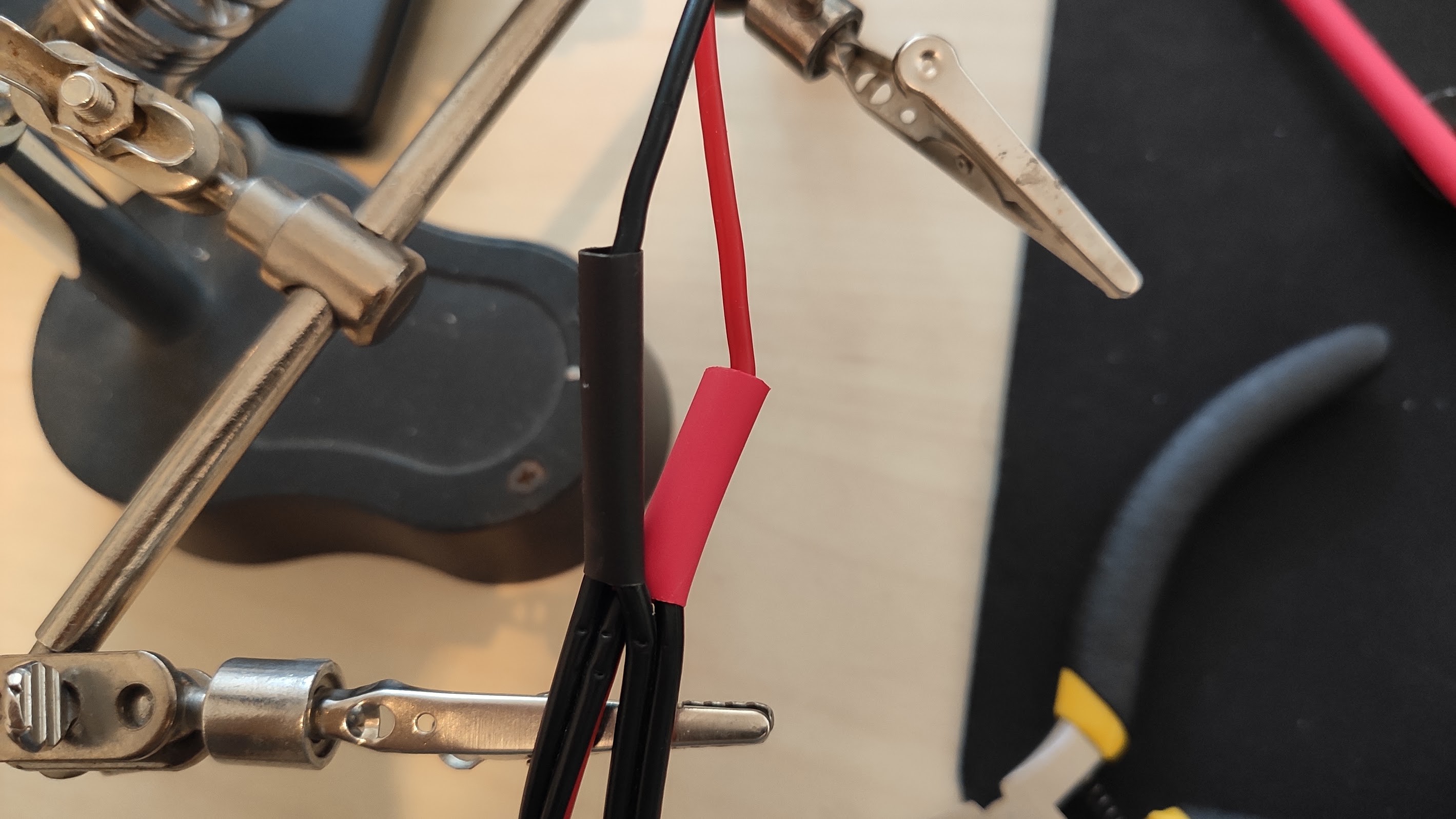
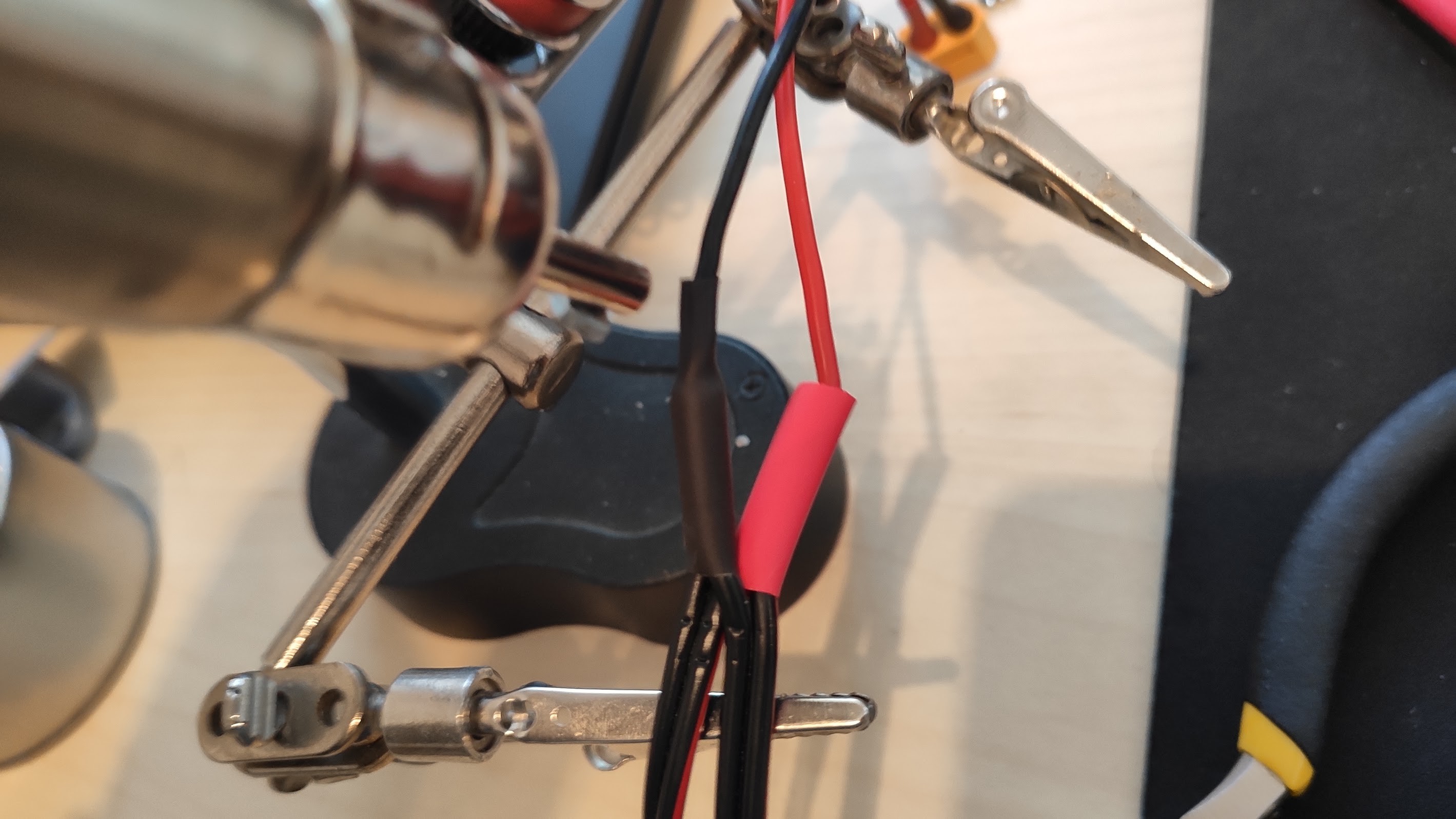
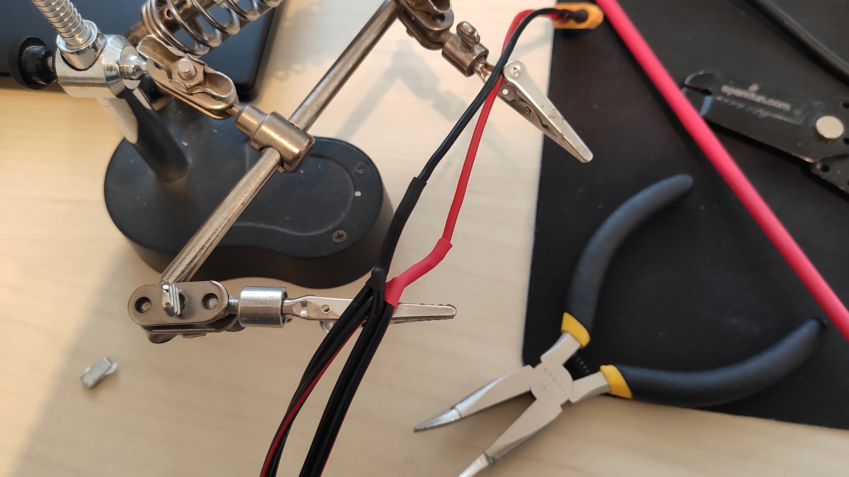
Do the same for the battery connector wire, and then wire them at the tips. Make sure to have the polarity right, or you'll have some short lived fireworks. Don't forget to use some heat shrink tubing - pull it all the way down on the battery connector wire, put it on both negative and positive leads, from the start or you'll surely forget.
![]()
![]()
I use a hot air soldering station on the heat shrink tubing as i can set a low temperature on it. Use a lighter if a station isn't laying around.
![]()
And the nice result:
![]()
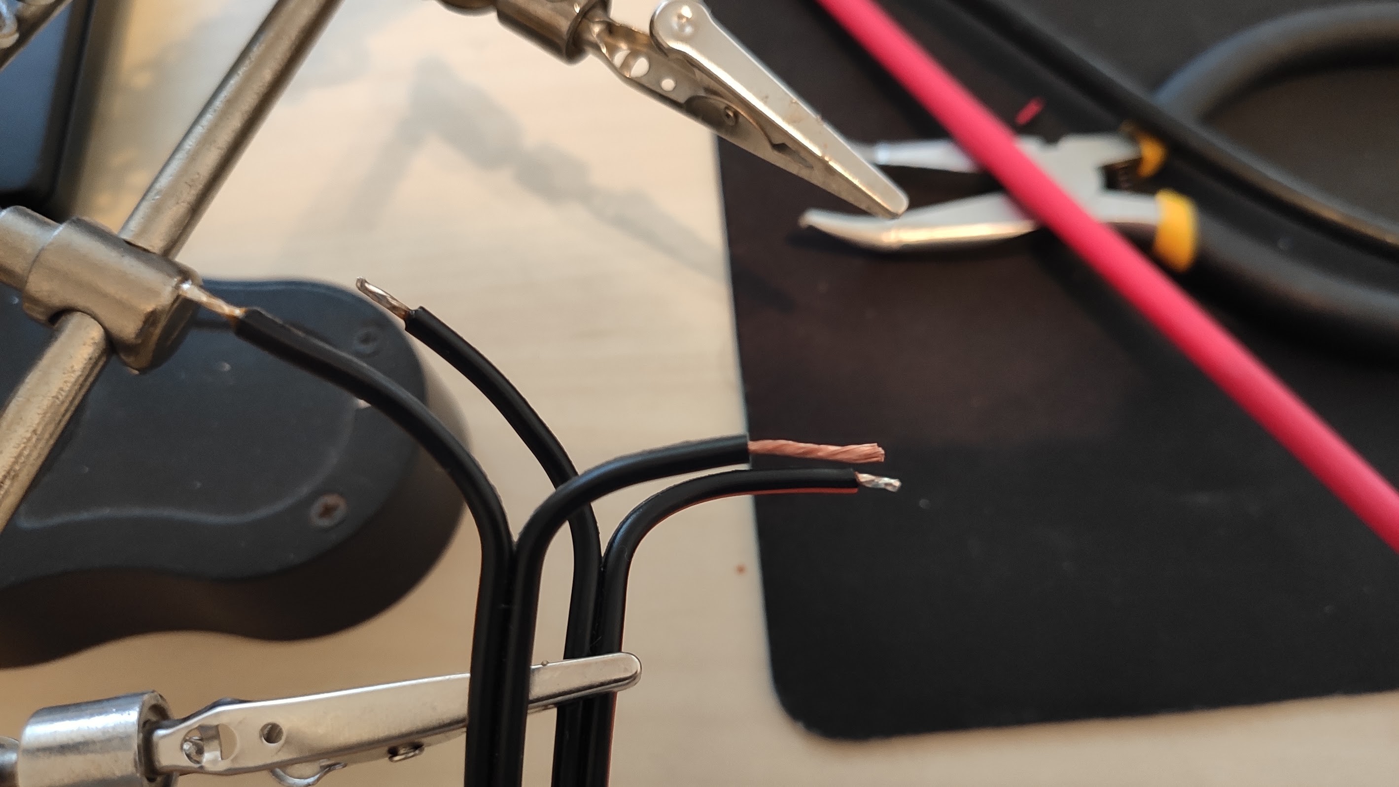
The other ends of the cables need to be stripped about 7mm, except on negative wire, which you might want to strip to about 15-20mm, this will be screwed on the resistance for the power meter. Put solder on the shorter wires, just enough so the strands won't split, ex:
![]()
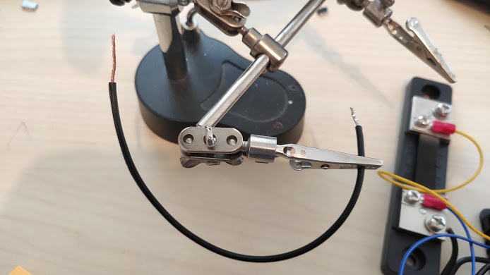
You need one more "negative" wire of about 15cm, stripped short and soldered on one end, and stripped long, no solder on another end.
![]()
Cut two more wires of 15 cm (with negative and positive wires), strip them short and put solder on. You'll need them in the next step.
-
7Wiring up
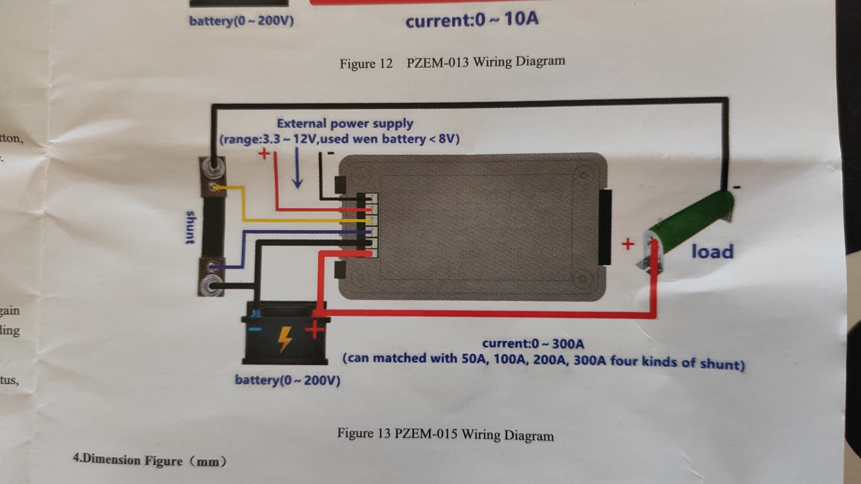
The diagram for the power meter:
![]()
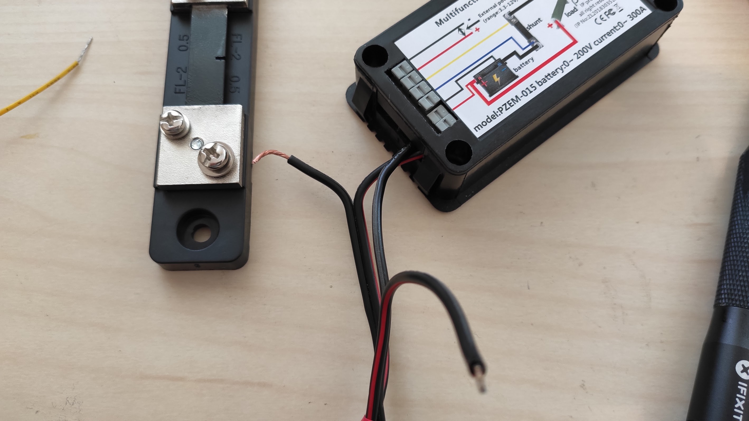
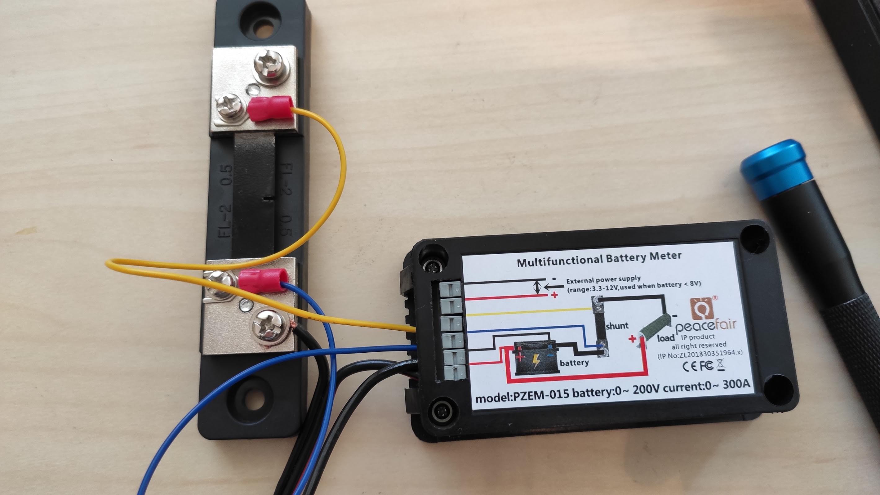
Start by inserting a negative and positive wire into the power meter, according to the diagram. The long stripped wire into the shunt resistor, yellow and blue wires (that come with the power meter).
![]()
![]()
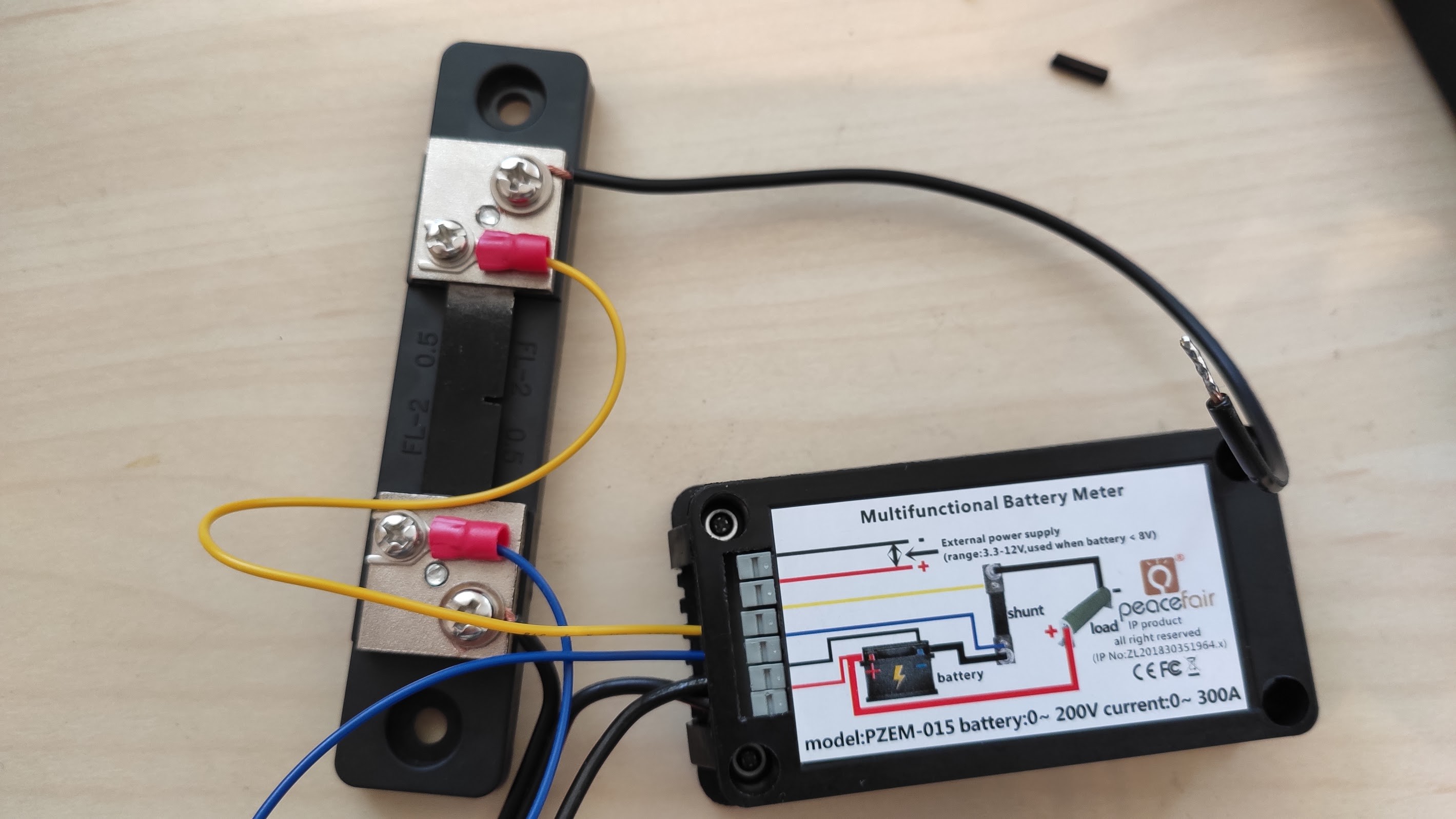
Also screw in the single wire.
![]()
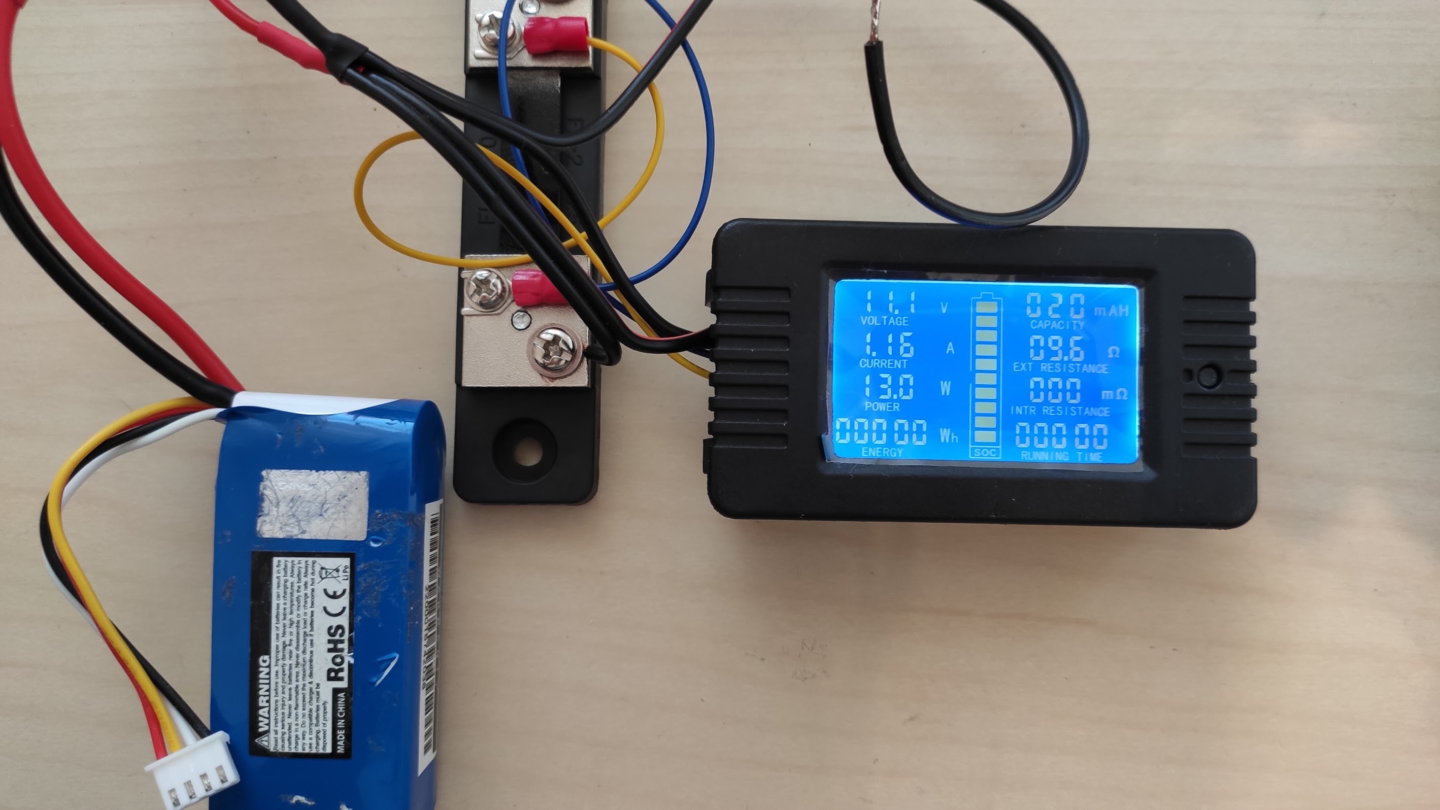
Just test that no smoke is coming out, by connecting a battery (the values are incorrect until you connect the load):
![]()
-
8Wire motor drivers
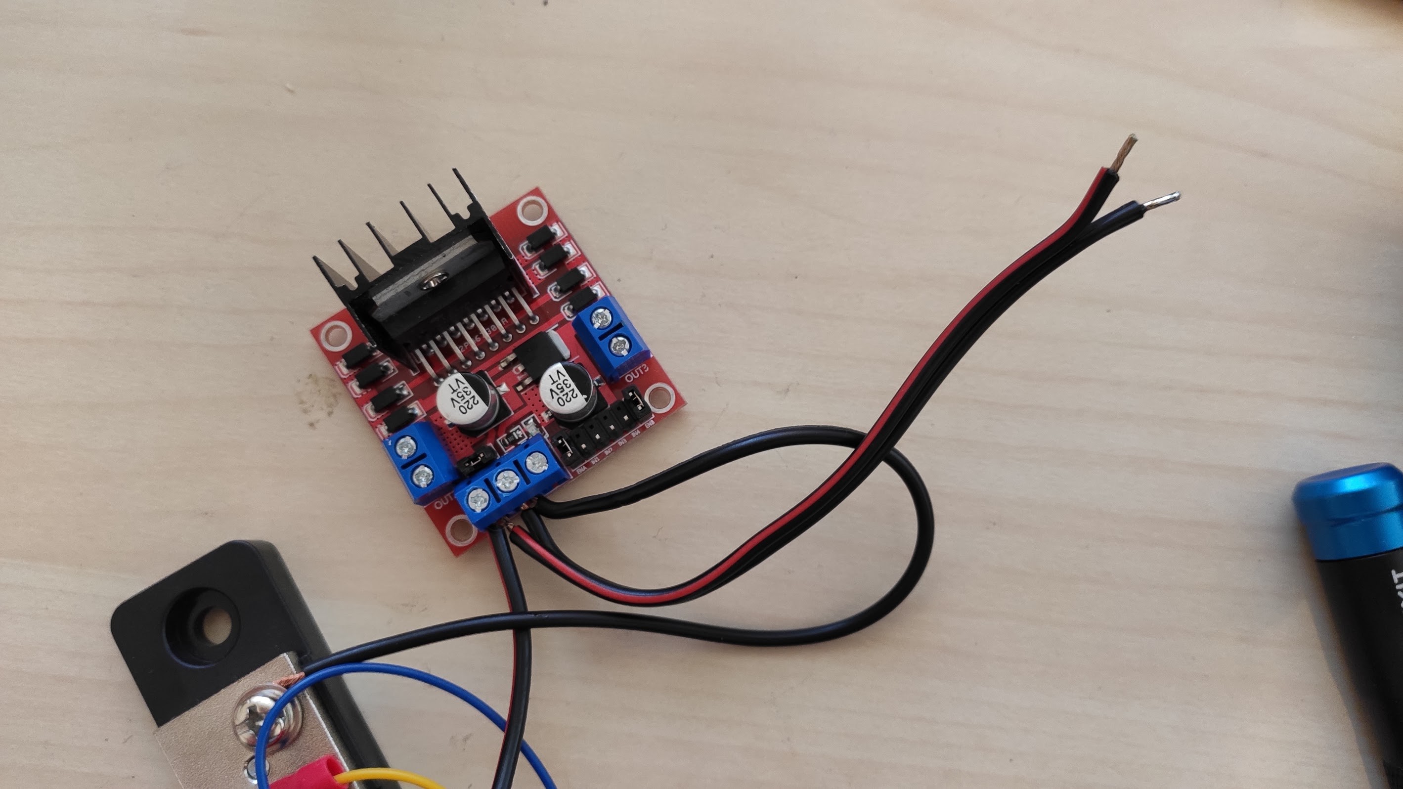
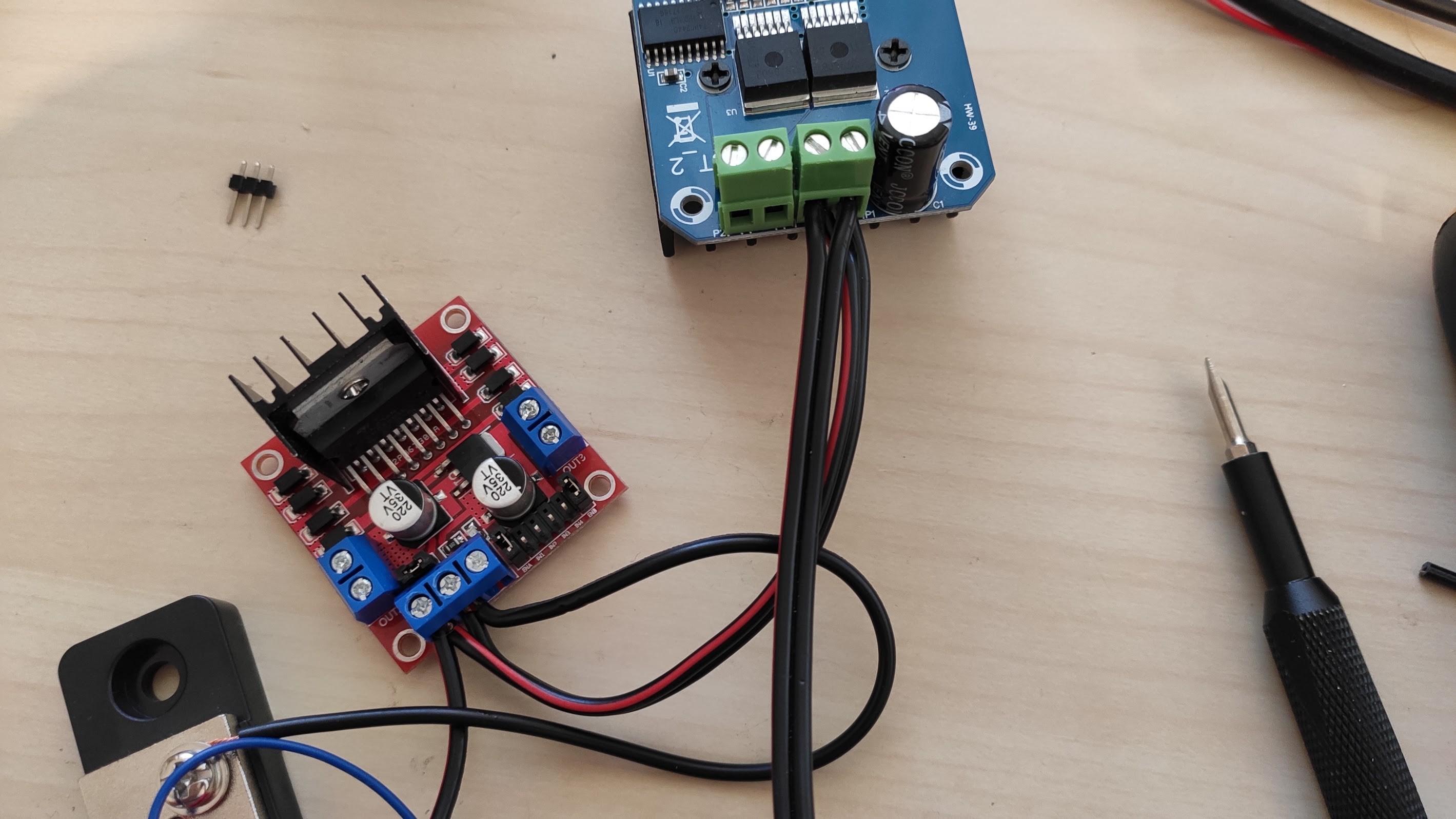
Insert the negative and positive ends into the dual motor driver, and also insert the other wire that we cut before, so we'll continue the power lines to the single motor driver. Triple check the polarity markings on the wires.
![]()
Do the same for the other motor driver board:
![]()
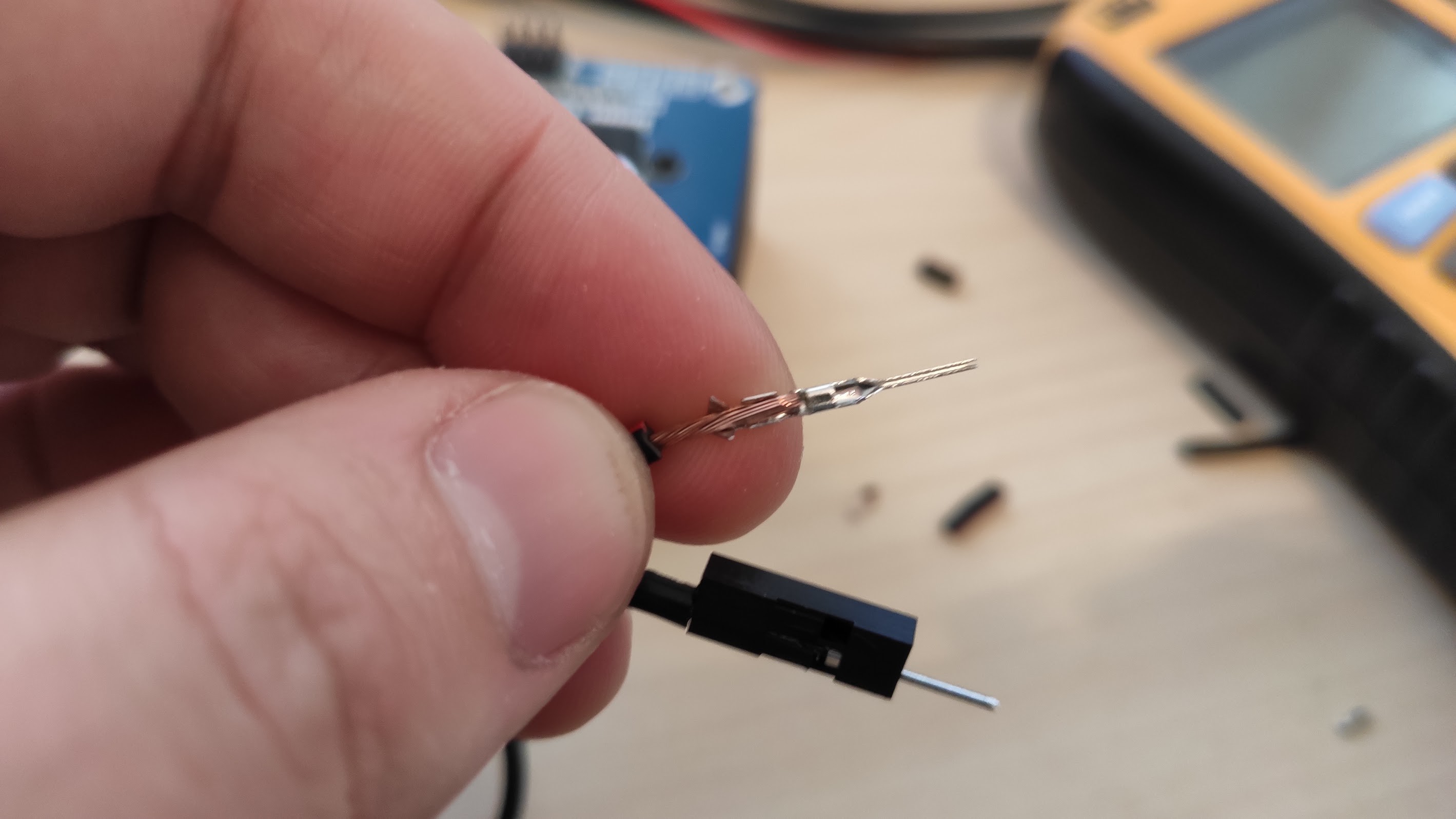
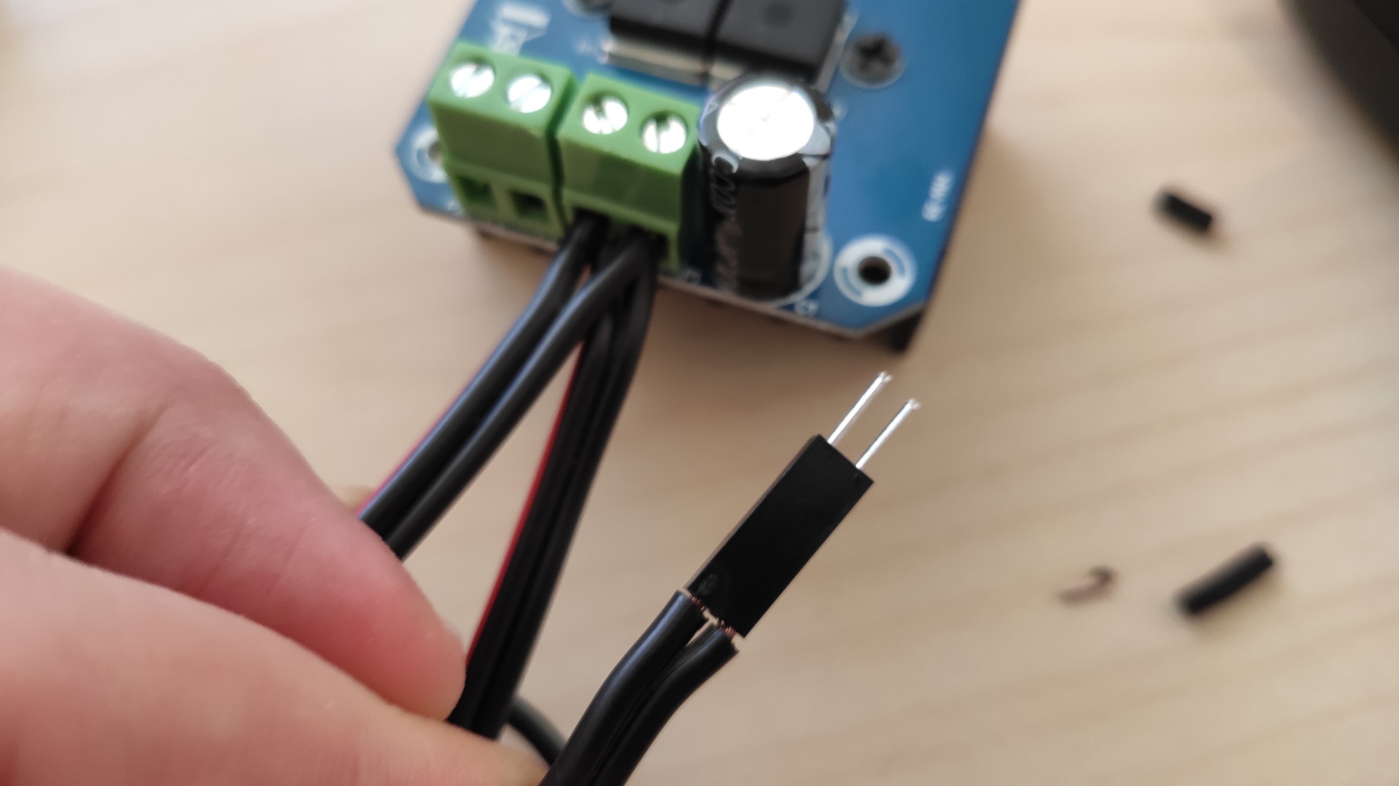
At this point trim the last exposed wire ends to cut the soldered part, and put some connector so that you can insert it into an arduino board (many other alternative options you can use)
![]()
![]()
-
9Wire motors
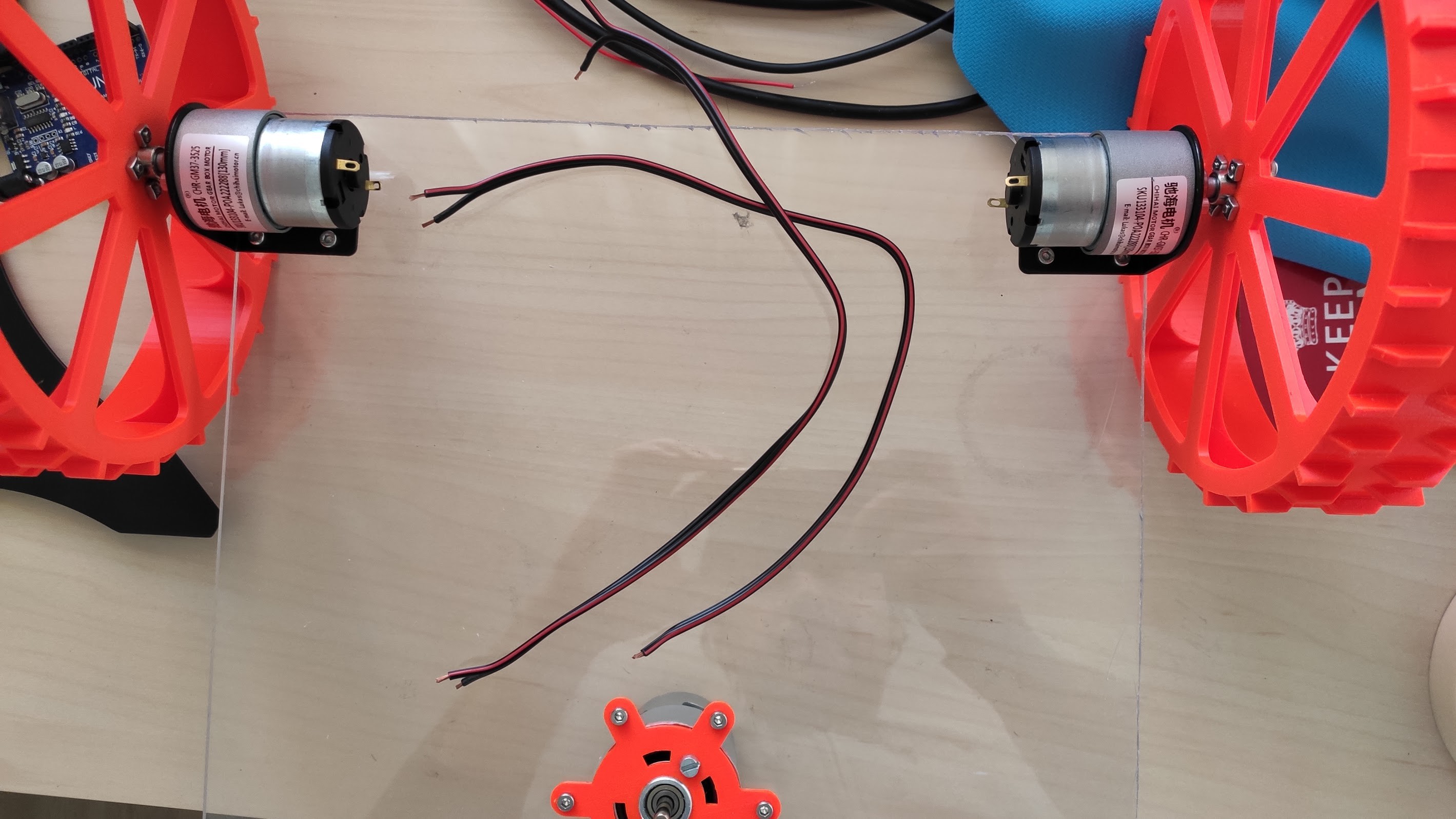
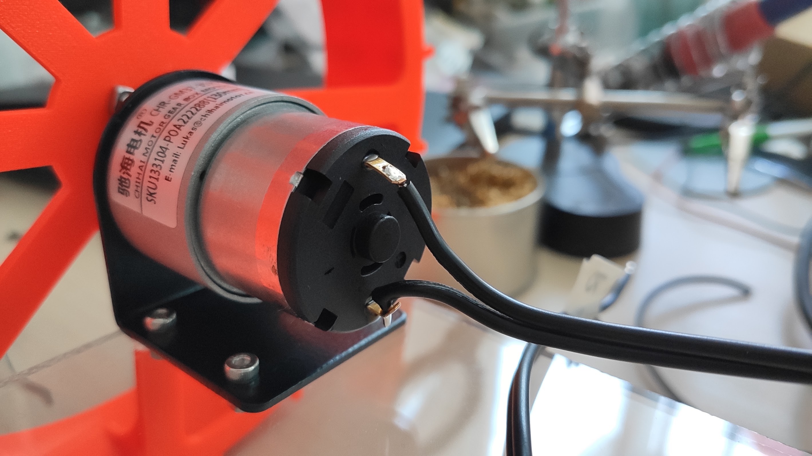
Two 20-25cm wires should be enough. The simplest way to solder is to put some solder on the ends of the wires first, put flux on the motor terminals and heat it up. Insert the wires as in the picture (the second one) from inside out, and solder. You might want to follow the polarity as specified on the motor (if there is any):
![]()
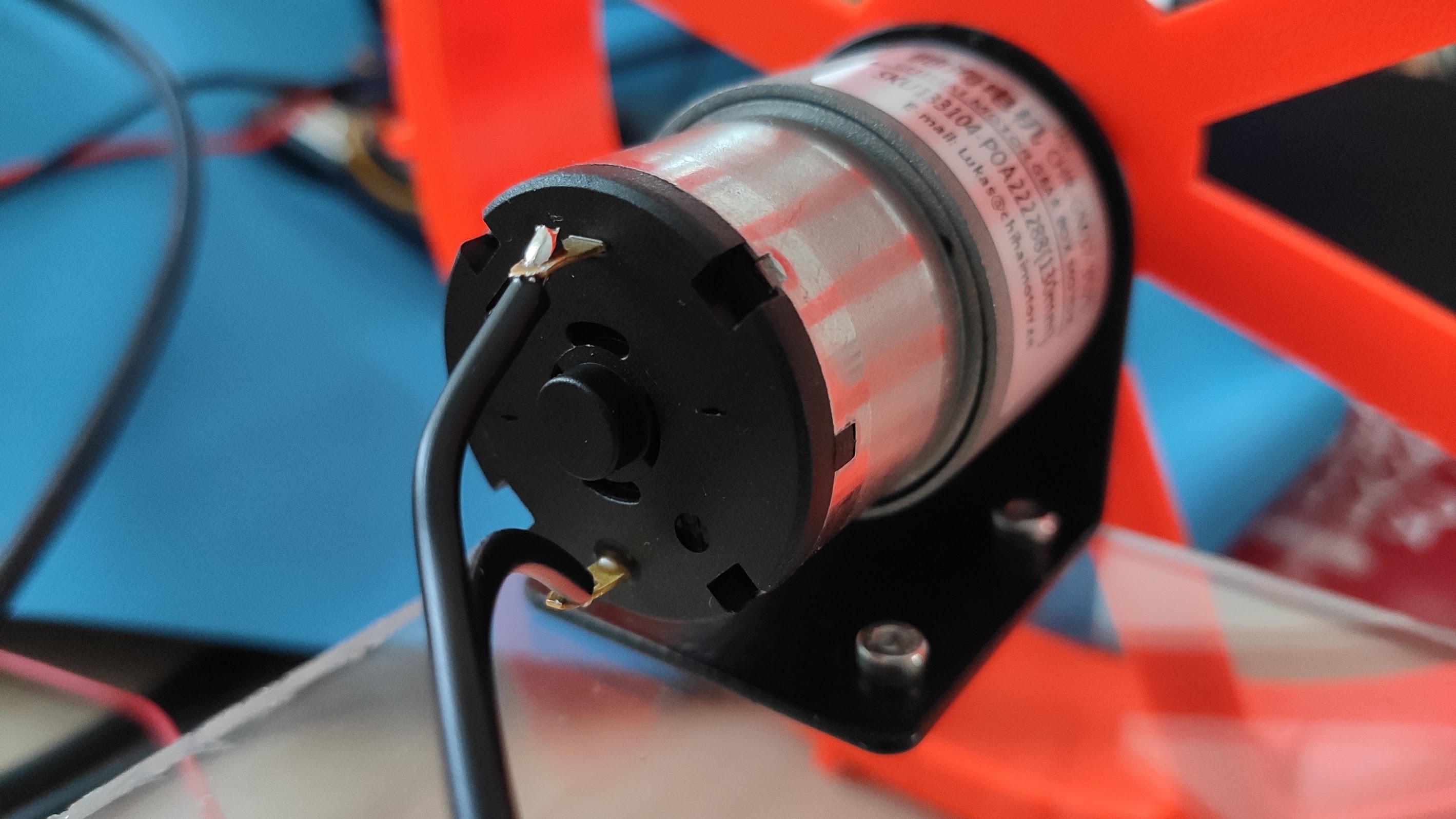
The long rectangle is the negative terminal:
![]()
![]()
You might notice that the wire insulator has deformed on the bottom wire, because I heated it for too long. Try to minimize the time your keeping the soldering iron on the terminals.
-
10Mount electronics
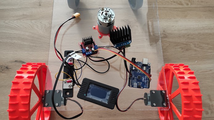
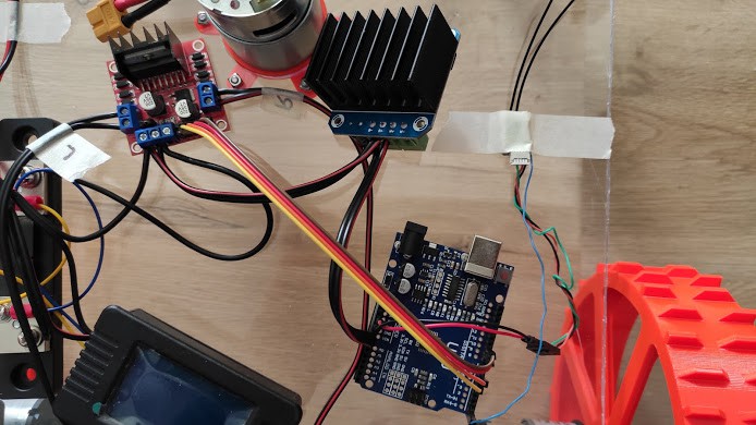
Mount the electronics on the platform. Connect the motor wires to the dual motor driver. Add an arduino board and connect the power to Vin and GND (it should handle up to 17-19V). Also connect the 4 signal wires on the dual motor driver to the Arduino board in the following order: 5, 6, 9, 10.
![]()
You might want to fasten the components with some single/double sided tape.
Connect a RC Receiver with SBus port (SBus to RX port on Arduino), you need to wire an inverted SBus signal.
![]()
Triple check all the polarities and connect a battery. If no smoke comes out, you're good.
 Radu Pascal
Discussions
Become a Hackaday.io Member
Create an account to leave a comment. Already have an account? Log In.