-
1Choose a USB hubTo cut costs I chose a cheap Chinese USB hub: https://www.aliexpress.com/item/4000040290804.html. It's built very cheaply but it works.
-
2Install an operating system onto Raspberry Pi Zero
I used a NOOBS distribution: https://www.raspberrypi.org/downloads/noobs/
-
3Set up Raspberry Pi to automatically connect MIDI
Place the following files on your desktop (/home/pi/Desktop):
PORTS=`aconnect -l | fgrep "client" | fgrep -v "client 0:" | fgrep -v "client 14:" | grep -o "client [0-9]\+:" | grep -o "[0-9]\+"`;

for port1 in $PORTS; do
    for port2 in $PORTS; do
        if [[ "$port1" != "$port2" ]]; then
            aconnect $port1 $port2
        fi
    done
done
while :; do
    /home/pi/Desktop/connect-midi.sh
    sleep 1
done
Change permissions for both of these files to allow executing them by running these commands in console:
chmod +x /home/pi/Desktop/connect-midi.sh
chmod +x /home/pi/Desktop/connect-midi-loop.sh
To test if these scripts work connect the USB hub using a USB OTG adapter to the Raspberry Pi. Run this command and then connect multiple MIDI devices to the USB hub to check if MIDI messages sent by one device are received by other devices:
/home/pi/Desktop/connect-midi-loop.sh
Finally, add this to the end of /etc/profile (it'll automatically start running connect-midi-loop.sh in the background when Pi Zero starts up):/home/pi/Desktop/connect-midi-loop.sh 2> /dev/null & -
4Optional: change boot settings
To slightly improve performance and speed boot up times you can tell Pi Zero to boot into console instead of a desktop environment. Probably the easiest way to do this is by using raspi-config. Run "sudo raspi-config" in console, then choose Boot Options -> Desktop / CLI -> Console Autologin.
It may also be a good idea to disable "Wait for Network at Boot" and "Splash Screen" -
53D-print an enclosure
At this point you got a working prototype. However, it's incredibly fragile and hard to use. To prevent things from disconnecting, protect the internals, make the device more portable and compact, you should build some kind of an enclosure. I 3D-printed mine but if you don't have a 3D printer you can use any other box/enclosure or even use cardboard.
Building an enclosure allows to solder USB hub directly to Pi Zero as well as add a power switch.
Note that while my enclosure has holes for Pi Zero's HDMI and USB jacks, USB jacks cannot really be used since that's how USB hub and the power switch are connected. And when it comes to the HDMI jack, the hole may be to be too small to properly connect a micro HDMI cable/adapter. I increased the size of the holes before publishing the design on Thingiverse but I haven't changed the bottom plate which may be needed. -
6Solder 4 wires to USB hub
Disassemble your USB hub and find the place where the cord is connected to the PCB. You'll see 4 wires:
- black (ground)
- red (Vcc)
- green (Data +)
- white (Data -)
You can desolder these 4 wires and solder your own but my advice is actually to not do that and instead cut the cord, expose the 4 wires and solder your own wires to each of them. That way you're not risking damaging PCB pads.
-
7Mount USB hub to the enclosure
Drill a large hole at the bottom of USB hub case in order to pass wires. Also drill some screw holes (in both USB hub case and the 3D-printed enclosure) and mount USB hub case on top of the 3D-printed enclosure.
-
8Solder 2 wires to USB Type B jack
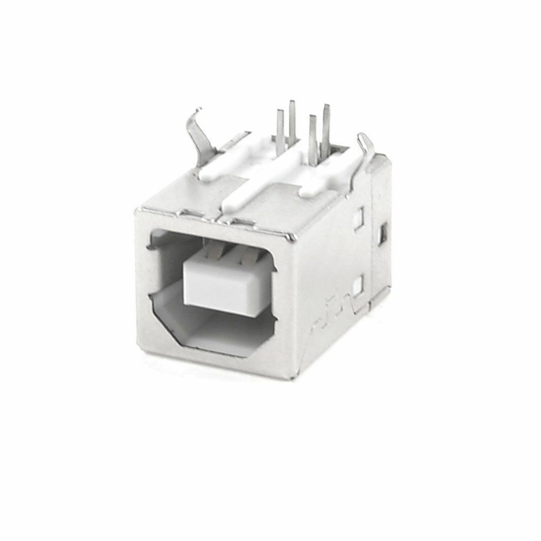
If we want to have a power switch we can't use Pi Zero's USB jack. I chose a large USB Type B jack because it's large and more sturdy but you can use mini- or micro-USB jacks as well.
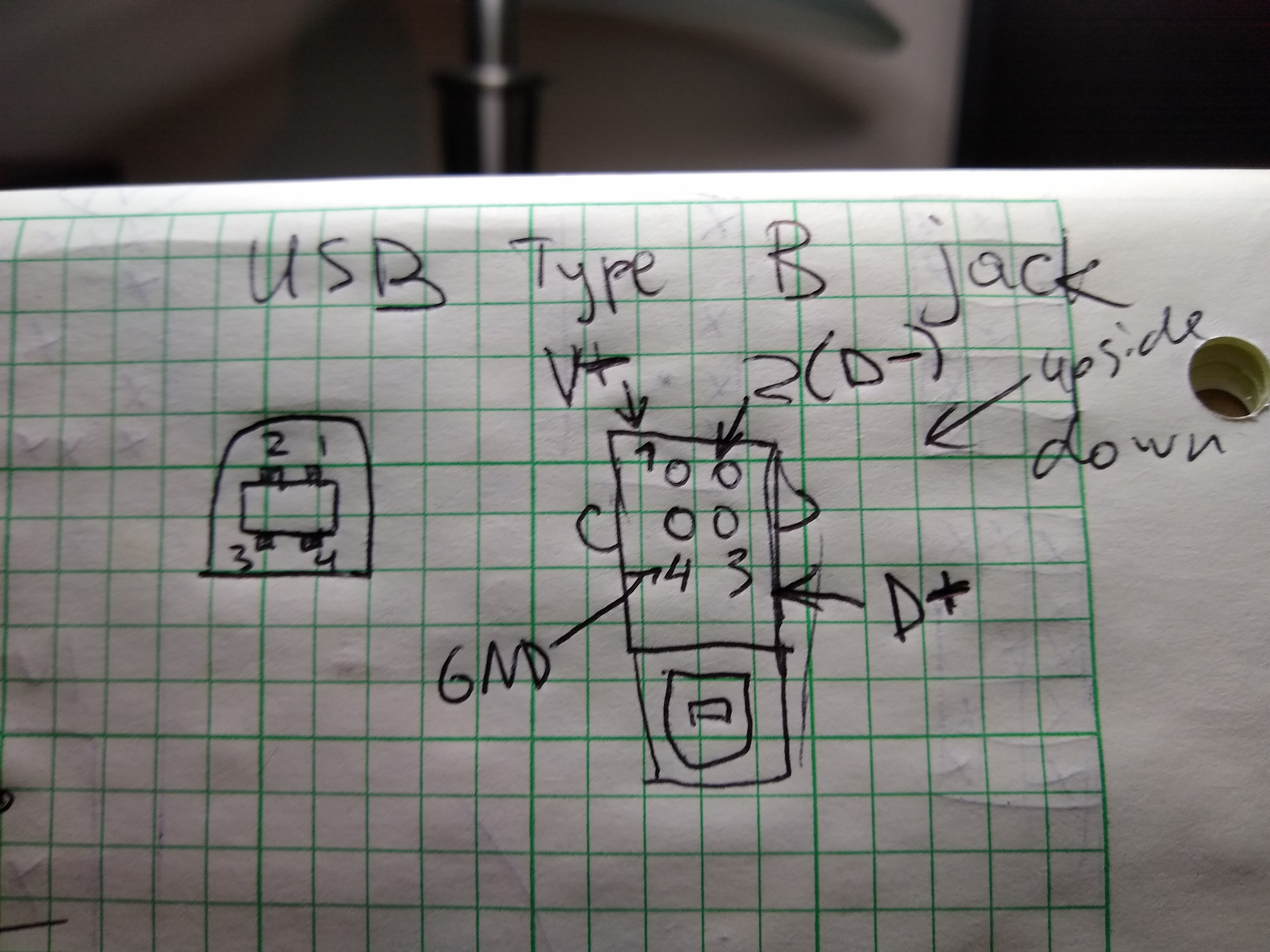
Use multimeter to confirm what pin corresponds to what of the 4 wires of the USB protocol (you can google "USB pinout"). In my case it was this:![]()
![]() Since we're only interested in power, we don't need to solder wires to D+ and D- pins.
Since we're only interested in power, we don't need to solder wires to D+ and D- pins.
When you connect the ground wire (black), also solder it to the ground wire from the USB hub, as well as an additional wire that will later be connected to Pi Zero. -
9Hotglue USB jack to the enclosure
If you're using my 3D-printed case, USB jack hole located is too low, so in order for it to not bump into the Pi Zero I decided to hotglue it upside down.
-
10Mount the power switch
The switch is going to have 3 pins. Use multimeter to determine what pins are connected when the switch is in the On position. One of these pins needs to be soldered to the Vcc wire from the USB jack. The other pin needs to be soldered to the Vcc wire coming from the USB hub, as well as to a Vcc wire that will later be soldered to the Pi Zero.
$20 USB MIDI host
Prices for USB-MIDI host devices typically start from $100. This is an attempt to create a cheap DIY alternative

 Since we're only interested in power, we don't need to solder wires to D+ and D- pins.
Discussions
Become a Hackaday.io Member
Create an account to leave a comment. Already have an account? Log In.