-
11Solder wires to Pi Zero
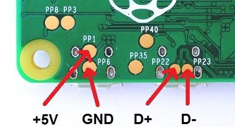
Raspberry Pi Zero has these test pads at the bottom that allow to bypass both of its USB jacks:
- PP1 is Vcc (+5V): solder Vcc wire from the power switch here
- PP6 is GND: solder ground wire from USB jack and USB hub here
- PP22 is Data +: solder Data + wire from USB hub here
- PP23 is Data -: solder Data - wire from USB hub here
![]()
-
12Mount Pi Zero to the bottom plate of the 3D-printed enclosure
My enclosure is designed to use 5mm M2 standoffs.
-
13Close the case and screw top and bottom parts from the sides
Use short M3 screws
$20 USB MIDI host
Prices for USB-MIDI host devices typically start from $100. This is an attempt to create a cheap DIY alternative

Discussions
Become a Hackaday.io Member
Create an account to leave a comment. Already have an account? Log In.