-
Special Review - ft. PCBway
06/15/2020 at 10:15 • 2 commentsHello again makers!
PCBway has recently been kind enough to produce a few of the V3.2 boards for me! Thanks PCBway!
So let's jump right in and have a look at what these boards look like.
Ordering the boards:
The ordering process was very easy and user friendly. All i needed to do was drag and drop my Gerber files and select the options for my board. The prices are also incredibly cheap starting at 5 single layer boards for only AU$7 !
Opening up the box:
The boards arrived in two weeks which is quite quick considering they all the way in China and I'm all the way over here in Australia. They came in this neat little box:

Inside, the boards were wrapped tightly in a ball of bubble wrap and a vacuum sealed bag. Nothing else was in the box. Over all, the packaging was pretty good.
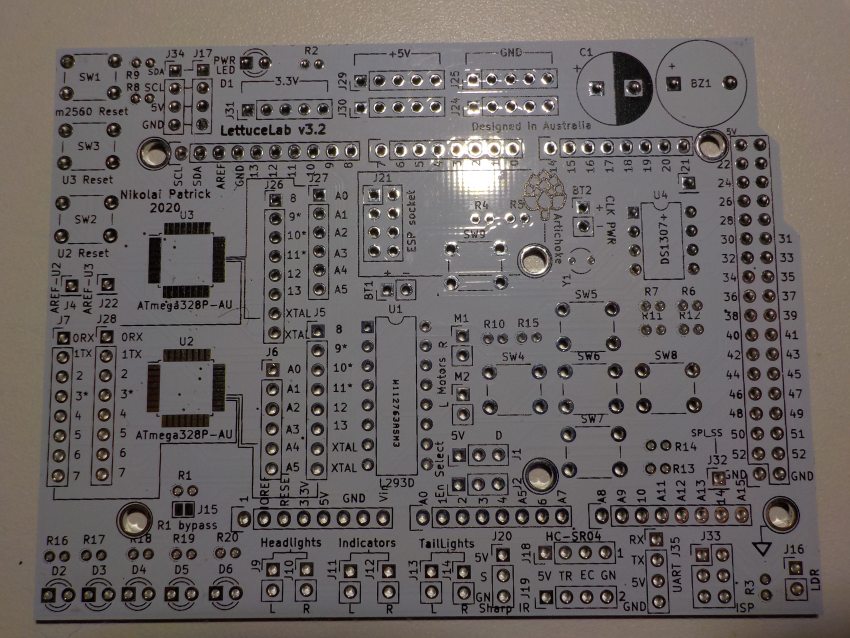
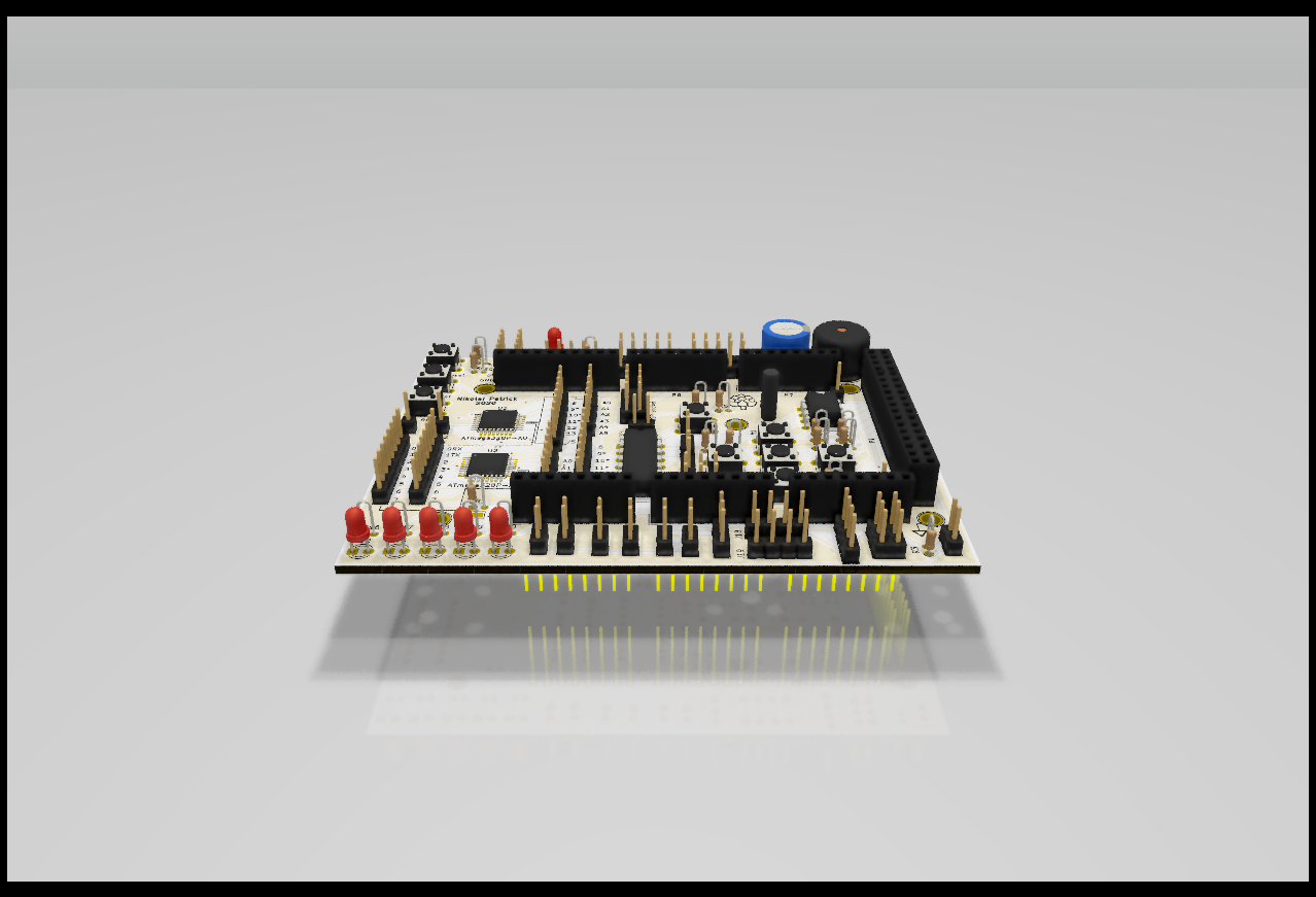
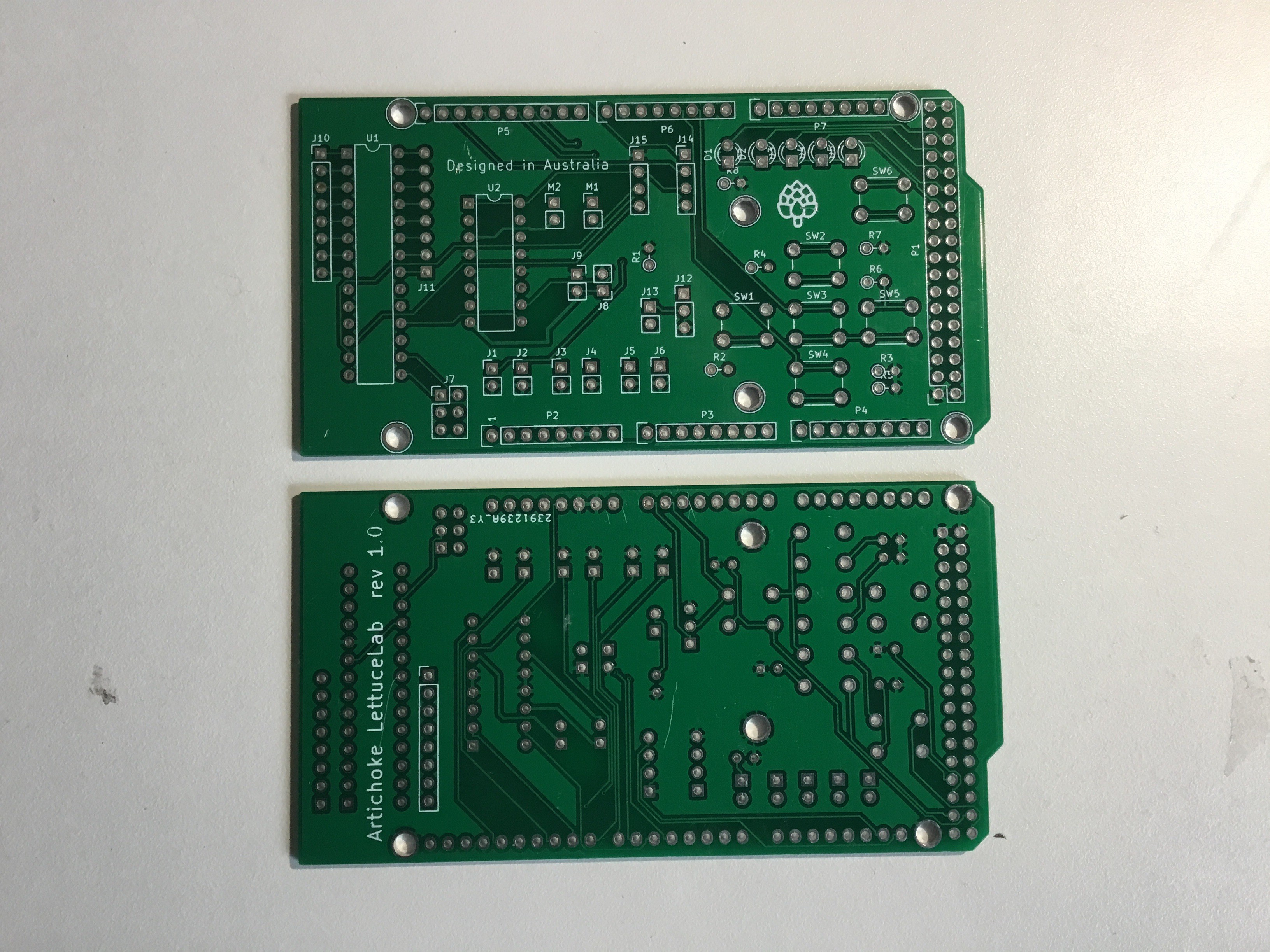
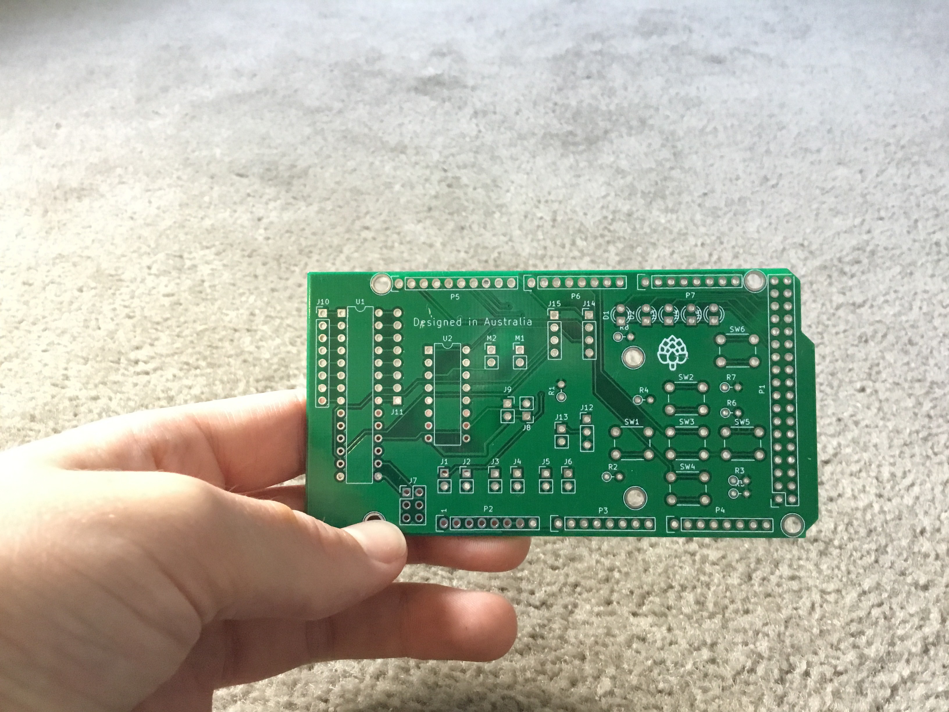
Looking at the PCBs
Quality:
The PCBs were made out of nice, strong material and I actually even measured the thickness with a pare of calipers and they measured 1.72mm.
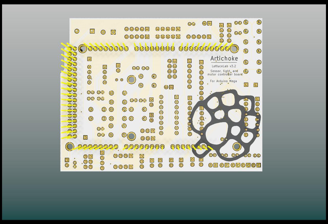
Copper and drilling:
All holes were drilled to size and none were askew or out of alignment. The rings for the holes were coated with HASL and no blockages were found in any of the boards. Copper traces underneath the solder-mask were really... well... underneath the solder mask. It is hard to really tell how good they are but i saw no obvious mistakes.
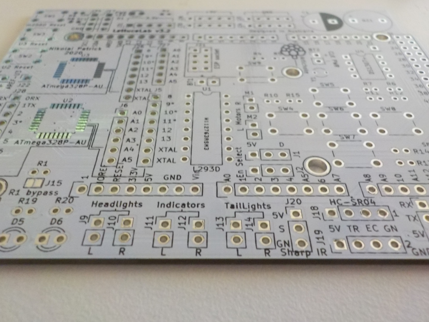
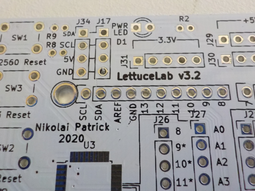
Solder-mask and silkscreen:
All boards were covered in a professional looking shiny white solder-mask.
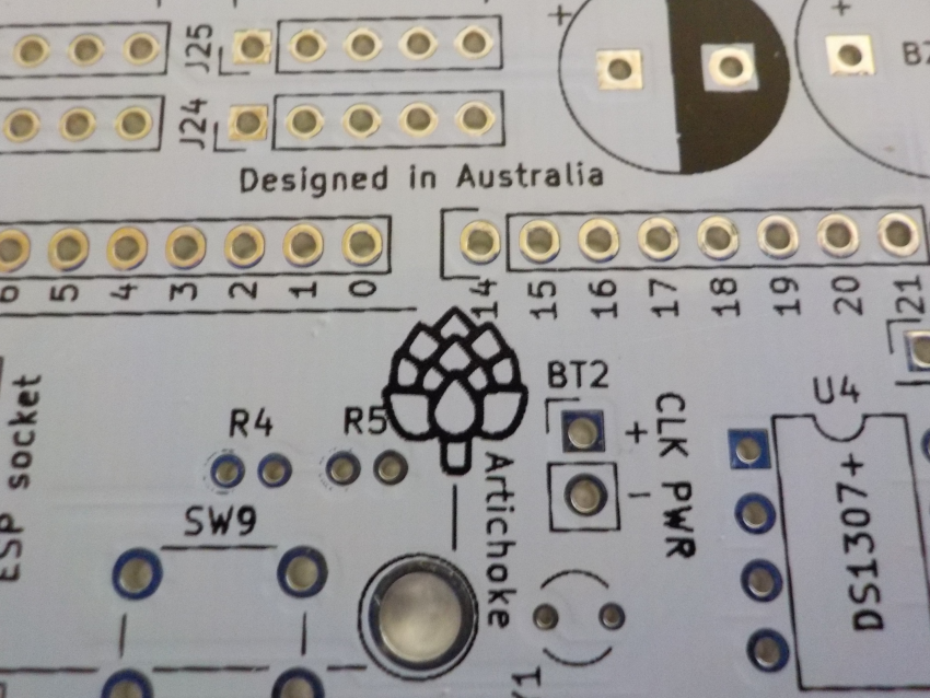
The silkscreen was very nice as well however it did somehow seem slightly thinner than the traditional white silkscreen. I also noticed that the rings around every resistor were not entirely there and came in little dots. My final observation was that the whole position of the silkscreen would shift slightly from board to board. This could be picked up around the mounting holes.
Ordering your own boards
A big thanks to PCBway for supporting me on this project! If you want to get cheap and good quality boards like this, head over to pcbway.com or click their logo below.
With real-time production tracking fast delivery, low prices, and amazing quality boards, I would highly recommend them.
Thank you PCBway! I hope you are all well during this pandemic,
Nikolai.
-
V3.1 and 3.2
06/15/2020 at 09:46 • 0 commentsVV3.1 and 3.2 minor board size adjustments.
- Size slightly modified to keep under 100 x 100 mm in order to lower production costs.
-
V3.0 designed
06/15/2020 at 09:22 • 0 commentsV3.0 is here! The V3.0 is a huge improvement compared to V1.0 and V2.0.
Here are some things that are different:
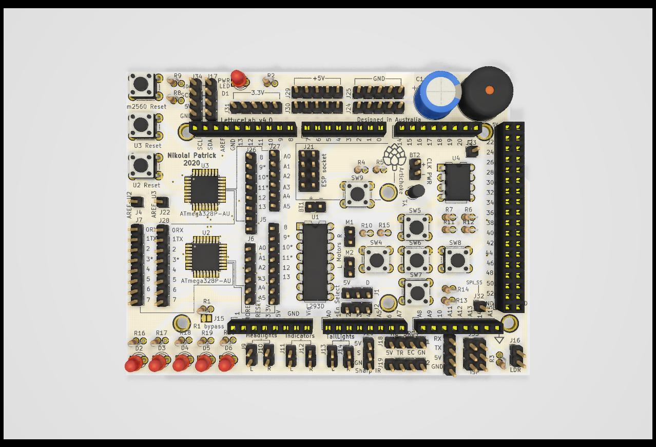
- As seen in the pictures below, the board has been extended on the sides to fit all the components.
- Each LED has it's own resistor. (a fix from V2.0)
- Instead of IO extenders, there are 2 ATmega328Ps in SMD. They are bussed together along with the Arduino Mega on I2C.
- Reset buttons for Arduino Mega and the two mega328Ps.
- Thicc capacitor for aid of power consumption.
- Buzzer
- ESP8266 WiFi socket.
- Real Time clock
- Power headers
- Buttons
- Motor driver
- Digital ultrasonic sensor connectors
- analogue IR sensor connector
- LDR sensor connector
- power LED
- SPI header
- I2C headers
- UART header
Files and more details will come out shortly.
Hope you are all well during this pandemic!
Nikolai.
-
V2.0 Designed
06/13/2020 at 07:17 • 0 commentsV2.0 design finished.
Basically a polished up version of the v1.0 board
Mostly only minor fixes. These include:
- Labels on the Arduino Mega pins.
- Labels on the board pins.
- Power header added.
- I2C address selector on IO expander fixed.
- Board size adjusted
At this point, the V2.0 board has not been tested.
Files will be available for those who wish to make it
-
PCBs in testing
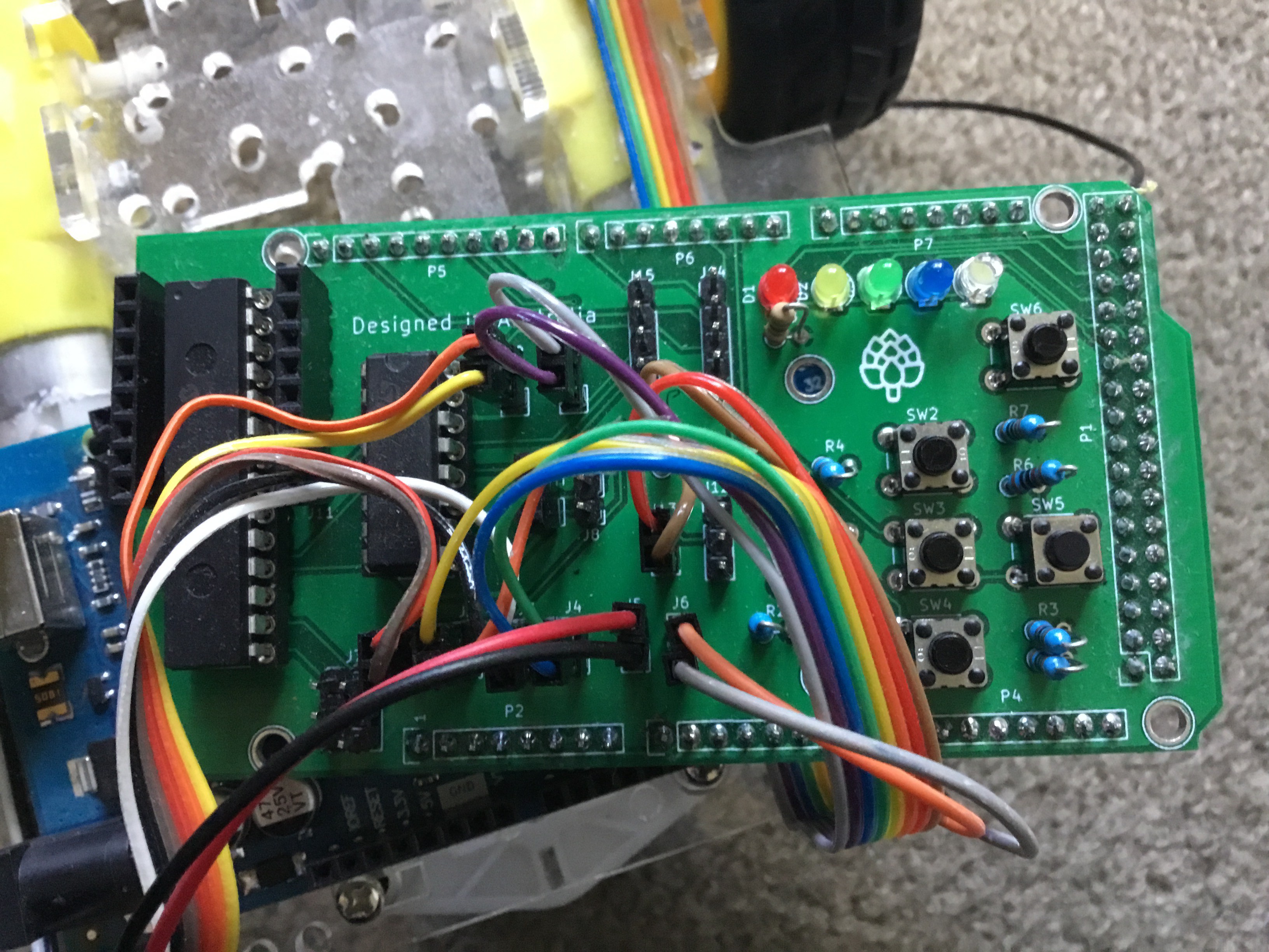
04/27/2020 at 02:27 • 0 commentsThings that worked:
-MCP io expander was detected on i2c port.
-Motors worked as intended, motor driver was wired correctly.
-External headlights are worked correctly.
- IR distance sensor worked correctly.
-Buttons yet to be tested but were seen to be wired correctly.
-i2c display worked correctly.
Things that went wrong / improvements:-J7 2x03 IO extender address selector had different pin numbering layout between the schematic and PCB editor.
-Silkscreen for j11 was upside down.
-Onboard LEDs D1-D5 were connected with a single resistor on the cathode pins. This means only 1 LED can light up at a time. Correct usage would have been an individual resistor for each LED.
-Silkscreen labelling was poor. Some reference numbers overlapped each other and the labelling of the pin header functions and the Arduino Mega pins would be helpfull.
-A multi-use power header would have been useful. Space for a small one in the bottom left corner is present. -
PCBs received
04/27/2020 at 02:07 • 0 commentsPCBs received from fabricator.
-
Gerbers sent to fabricator
03/01/2020 at 03:28 • 0 commentsGerbers finished and PCB sent to fabricator, awaiting arrival.
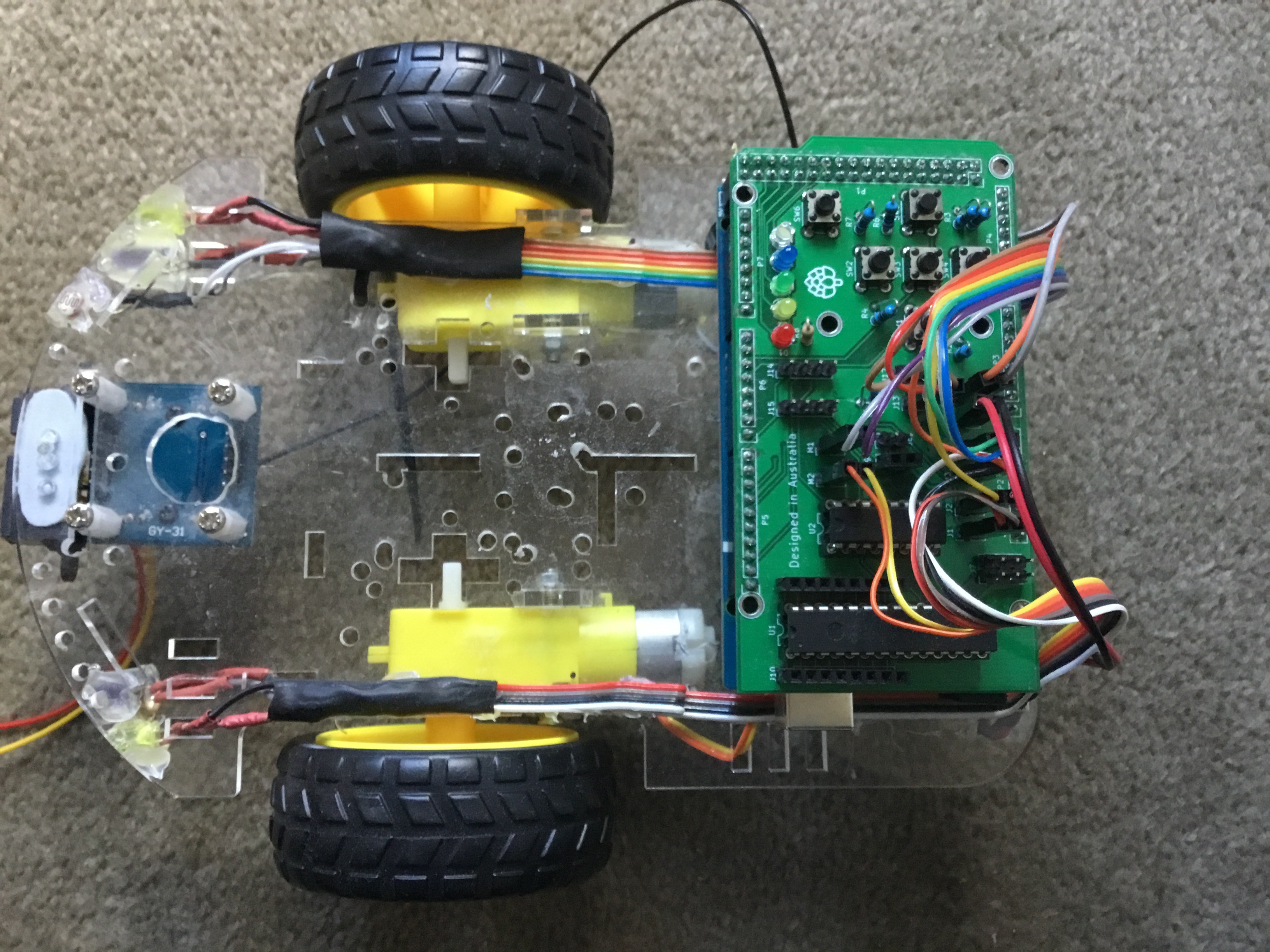
Artichoke LettuceLab Series
Powerful shields for a fully automated Arduino robot