 Marius Taciuc
-
1Disclaimer
I plan on adding the first code draft, which I write and test now. But before I do so, I want to leave this disclaimer here.
![]()
!!! Disclaimer - read this !!!
This firmware is purely for experimental and demonstrative purposes. This AI firmware is not the final tested version and it could take erroneous decisions that could lead to hazards. The designer assumes no responsibility for any of these consequences. Hazards could include, but are not limited to: severe injuries, explosions, domestic fires, death.
!!! Exercise caution at all times when testing it at your own risk !!!I just get chills when I think that I entrust a 50W - 400*C heating element into the hands of a self learning, decision making machine who could set my house on fire when I leave the room. Errr! So please be careful. At least in the prototype phase until we conclude that is safe.
-
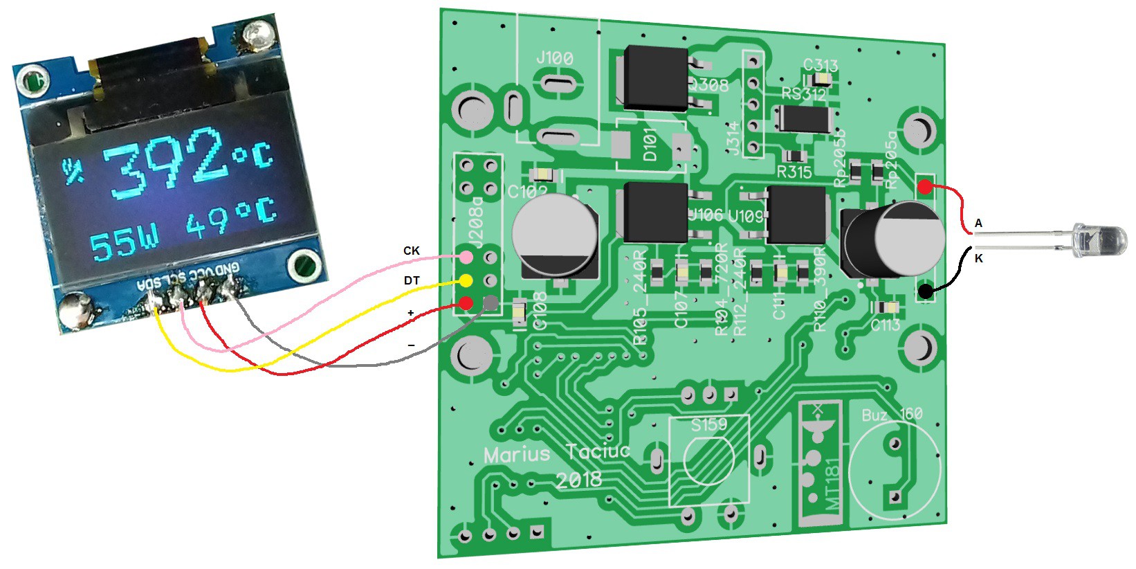
2How to connect the 0.96'' OLED display
Like I said, before I redesign this, I will use the PCB from my previous project. I uploaded the layout here so you don't have to go looking for it. This is how I connected the OLED display and the LED.
![]()
Then I bent the LED underneath the display and used a thicker piece of copper wire to secure the OLED into position like in the picture below:
![]()
I am planning to use that backlight LED to illuminate around the knob of the encoder. Or I might print a transparent case and the LED will shine through.


Discussions
Become a Hackaday.io Member
Create an account to leave a comment. Already have an account? Log In.