Michael Gardi
-
How Time Flies
06/17/2021 at 15:06 • 0 commentsIt's been about a year since I "finished" (is any project ever really finished) my Computer Lab Reproduction. Since then I did manage to get the PiDP-8/I reproduction by Oscarv that was mentioned in this writeup assembled and running. This is a super kit I would highly recommend to anyone interested. In addition I created a VT100 Terminal Reproduction of my own for my DEC collection. Here is a picture of them both in action.
![]()
A year ago when I wrapped up this project I thought that perhaps in a few months or so I would be able to bring my H-500 into kwartzlab to show to my wonderful and supportive maker buddies. Little did I know that a year later I would be thinking the exact same thing. Sigh. Hopefully this time I'm right.
-
More From John Hughes
10/31/2020 at 00:54 • 2 commentsJohn Hughes, the designer of the H-500 Computer Lab and author of the accompanying Workbook was kind enough to answer a few of my questions.
I asked John how the patch panel was constructed:
The patch panel surface of the Computer Lab is actually two layers. The top layer is a white plastic sheet with the component symbols silk screened on. The bottom layer was a PCB that was affixed to the top layer by soldering the patch panel rivets to the PCB panel. The layout of the patch panel PCB was single-sided and pretty simple.
I commented that the surface mounting of the components was way ahead of its time:
Yup surface mounting PCB components was bleeding edge mechanical technology in 1968-9. Computer Labs were totally hand assembled on a small DEC production line in Kanata, Ontario (just outside Ottawa). Surface mounting components did require special soldering tools and operator training. By the way while I said I designed the Computer Lab, my focus was on the EE part of the work. DEC had a mechanical design team in Maynard MA that did a great job on that part of the design effort. One additional point, there are two PCB’s, one for the IC part of the patch panel, the other for switches, lights, clock and power supply. The two boards are joined with soldered jumpers.
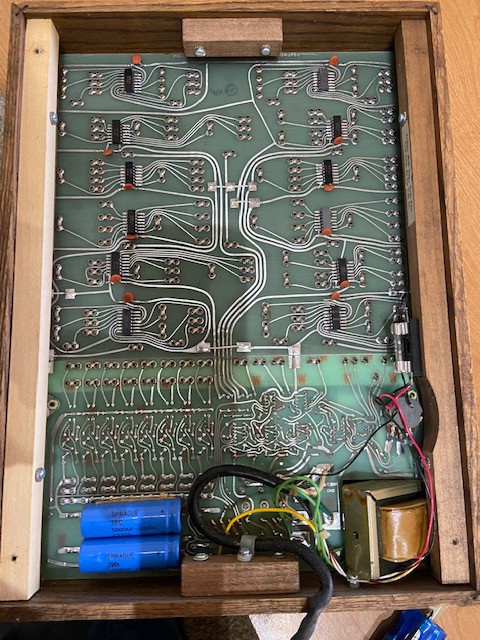
Here is a very good picture of the inside of his personal H-500:
![]()
Attached is an inside picture of my Computer Lab. In it you can see the color difference line between the two PCBs as well at the jumpers between the two boards.
I asked John if he had a copy of the schematic for the switches, lights, clock and power supply and sent him a fuzzy picture of one that was attached to the back panel of a unit. He was kind enough to check for me:
I opened my Computer Lab to see if there was an attached schematic inside the back cover as in your picture – unfortunately no luck.
I learned a lot from John today, and I certainly appreciate his reaching out and taking the time to share and even answer a few questions.
-
The Designer of the Original H-500 Computer Lab Reaches Out
10/30/2020 at 21:37 • 0 commentsI was honored to receive an Email from John Hughes the designer of the H-500 and author of the Computer Lab Workbook. With John's permission I would like to share that Email as it contains valuable historical insight into the project. John wrote....
Mike,
More than 50 years after I designed the Digital Equipment H500 Computer Lab and wrote the Computer Lab Workbook, it’s incredible to see that you have created a totally functional copy of the product. Congratulations on an extremely well executed project. Looking at the web pictures and videos I would have thought your Computer Lab had been made at DEC Kanata many years ago.
Since many of the folks looking at your Computer Lab copy likely have used a DEC Computer Lab at some point in their technical education, here’s a little relevant DEC history that you might find interesting.
In the mid 60’s DEC brought out a logic training system called the Logic Lab that used the discrete component logic modules that at the time were the building blocks of all computers. The Logic Lab was very flexible and powerful. In fact, DEC engineers used multiple Logic Labs to prototype the first PDP‑8S computer. The biggest problem with that prototype was suppressing the electrical noise associated with long leads and multiple Logic Lab chassis (and power supplies) – eventually though it worked.
By the late 60’s integrated circuit logic devices had displaced discrete device logic modules as computer building blocks. Add to that a Logic Lab base price of over $2,000 and that was well above the budget of many tech schools and universities – it was time for a replacement product.
Denny Doyle, the President of DEC Canada, wanted a locally developed and manufactured product to expand the role of the Canadian subsidiary. About that time, I joined Digital Equipment Canada as a relatively newly‑minted electrical engineer. Shortly after I was tasked with designing and writing a book to support an affordable logic training device for the technical education market based on the then‑popular TTL (Transistor-Transistor Logic) integrated circuits. The result was the H500 Computer Lab manufactured by Digital Canada that sold for $400 back in the late 60’s through the early 80’s.
By my recollection, about 4500 – 5000 Computer Labs were built over the life of the product. Almost all were sold to the technical education market to be used as the practical lab part of a course on digital and computer logic. Over the usable life of the product, my guess is that an average of 20 students (or more) would get to use each Computer Lab. That translates to a worldwide population of as many as 90,000+ technicians and engineers who gained their first practical lab experience with digital logic on a DEC Computer Lab.
The Computer Lab Workbook was key to the success of the product. It was an inexpensive paperback handbook that DEC printed in volume and distributed free of charge for product promotion (along with many other DEC handbooks). The book was a ready-to-use lab course for computer logic – that clearly appealed to educators. The first printing of the book, 100,000 copies, was gone quickly in about a year. A second printing of 100,000 was used up much more slowly and lasted for the remainder of the product life.
DEC sold a separate Computer Lab Teacher’s Guide written by Larry DeAngelo. It had answers to questions in the Computer Lab Workbook along with additional experiments and supporting material.
The advent of bipolar integrated circuits created a very large market to train engineers and technicians to design and maintain computers and digital electronic devices, including computers. Based on what I have read since, the Computer Lab was the market leading device to provide a practical lab experience to support that training in North America and Europe through the 70’s and early 80’s.
Integrated circuit technology has packed ever increasing functionality and performance at ever decreasing cost into a single device. A hobbyist today can purchase a full computer with storage and I/O on a small PC board for less than $50 on Amazon. Programming low cost chip processors has replaced logic design as the way to create unique products. Even so, the Computer Lab had a remarkably long run in a market with very fast changing technology.
Over 50 years after they were manufactured, Computer Labs still regularly appear for sale on EBay.com. Interestingly, surfing the web a while ago someone mentioned a still in service Computer Lab as recently as 2006 in Switzerland.
Mike, your creation of a Computer Lab copy is really cool. Again congratulations for a project extremely well done. Now there are two of us who have both designed and built Computer Labs … a little over 50 years apart.
Regards
John L Hughes
-
A Better Incandescent Look
07/01/2020 at 04:34 • 0 commentsBrightBlueJim pointed out in a comment to Dan Maloney's blog entry (https://hackaday.com/2020/06/28/reproduction-1960s-computer-trainer-really-pushes-our-buttons/#comments) that the lamps looked blue, which as he pointed out is not very incandescent like (the original used incandescents). The LEDs are actually white shining through translucent PLA diffusers, but they do look a little blue in the videos.
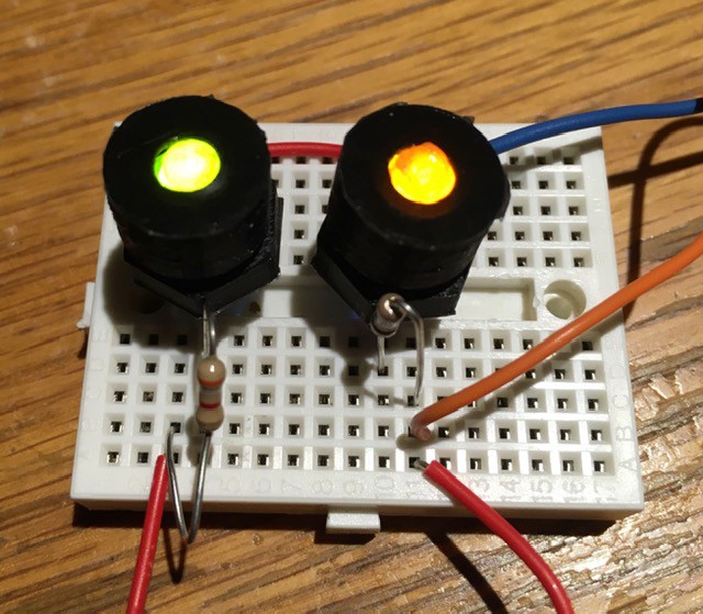
So I tried printing the diffusers in both yellow and in the same brown that I used for the rocker switches.
![]()
Hard to see in the picture but the yellow (left) doesn’t look too bad (better than the transparent IMHO), but the brown looked great after I changed the limiting resistor to about 330R to brighten up the LED. If I were doing it again I would definitely go with the brown diffuser.
-
Wiring the Lower Half
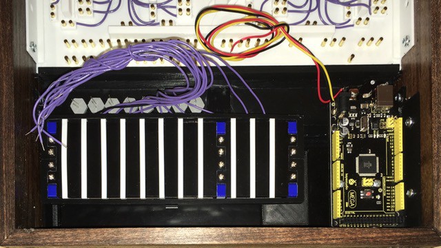
06/19/2020 at 23:02 • 0 commentsThe first thing that I noticed when I started the wiring was that the switch assembly wires (purple) and the light panel LEDs (grey hexes) were overlapping, making my life harder than it had to be.
![]()
So I removed the switch assembly and rebuilt it, moving the eight brown rocker switch wires to the bottom of the assembly (the pulse switches were OK). There is a nice channel on that side to run the wires between the frame and the assembly itself. Following this wiring diagram (which has a small change to the potentiometer power wire from the one posted previously)...
![]()
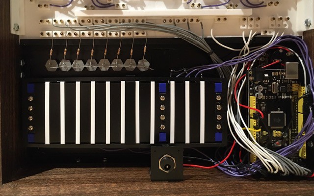
...it was pretty clear sailing and here is the result:
![]()
For reference the wire colors are:
- purple - switch inputs to Arduino
- grey - switch outputs from Arduino
- white - clock out and clock delay control from and to Arduino
- yellow - potentiometer input to Arduino
- red - power +, 9V to Arduino, 5V from Arduino
- black - ground
The LEDs are wired directly to the lamp inputs with a 4K limiting resistor (large enough to keep the brightness down to incandescent levels). While wiring the LEDs I noticed a pretty big goof on my part. The label for the lamp terminals should have read LAMP INPUTS. Doh!
![]()
Oh well nothing to do about it now. I have updated the patch panel STL file but will live with my error on this build.
All that's left to do now is run power up to the PCBs and the HIGH and GND terminals. Very excited to be this close.
-
Framing
06/11/2020 at 14:47 • 0 commentsWell my lumber and stain finally "arrived". It took my local Lowes 17 days to put together my "curbside pickup" order. Sigh. If I had access to my local maker-space (kwartzlab) I probably would have ripped something down to the required 1/2" x 3 1/4" board size that I needed, but I was "lucky" enough to find some "craft board" at Lowes in the required size.
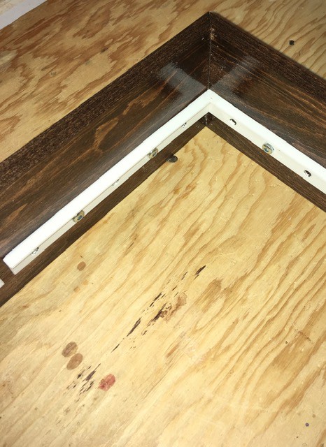
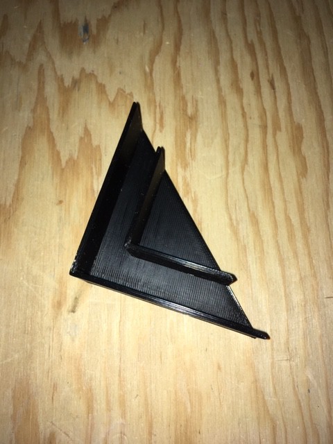
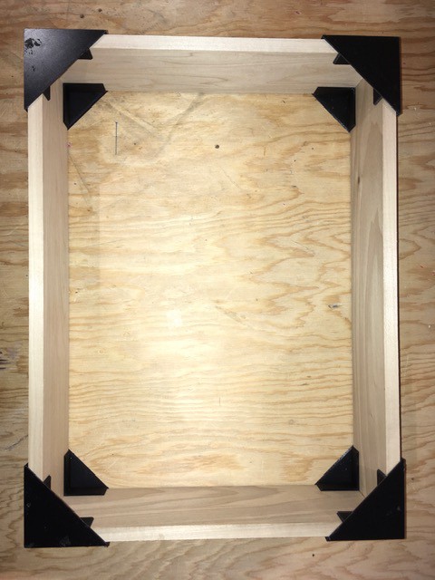
The other maker-space thing that I missed was access to their fine selection of corner clamps to put the frame together, so I had to improvise. I ended up printing some corner guides that worked quite well.
![]()
I mitered the corners of the frame and used the guides to align the boards while I glued and popped in a few brads.
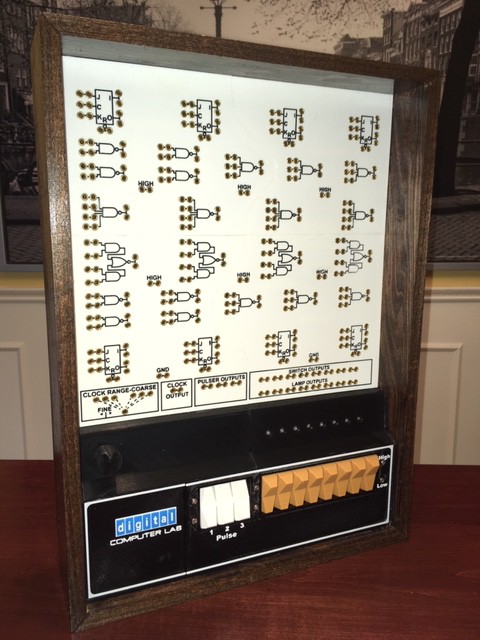
![]() Once dry I stained the boards then applied a few applications of clear coat. I was a little disappointed in the stain as I was expecting it to be a little lighter and redder like the original's "simulated teak". But given how long it took to get the stain I went ahead and used it.
Once dry I stained the boards then applied a few applications of clear coat. I was a little disappointed in the stain as I was expecting it to be a little lighter and redder like the original's "simulated teak". But given how long it took to get the stain I went ahead and used it.I printed some supports to hold the Plug, Light, and Switch Panels in place at their appropriate depths (1/2" for the Switch Panel and 1 3/4" for the Plug Panel) within the frame and attached them to the inside faces with 1/2" wood screws.
![]()
![]()
I attached the panels onto the frame supports with some E6000 Adhesive.
![]()
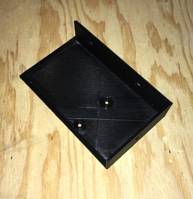
Finally I printed a mount for the Arduino Mega...
![]()
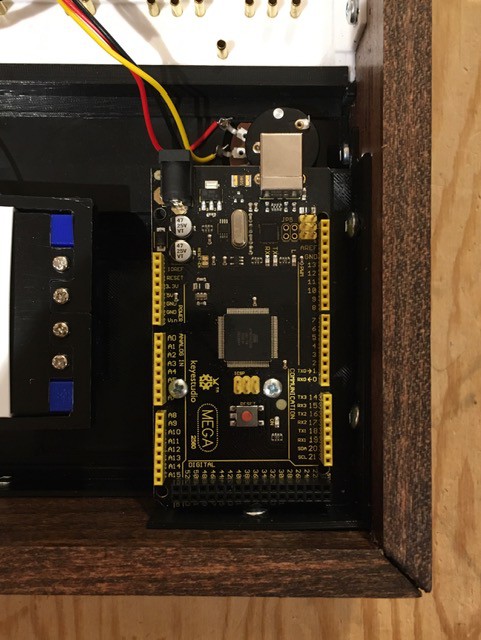
...and installed it in the corner of the frame underneath the potentiometer.
![]()
This feels like a major milestone to me. I basically just have to do the "integration" wiring and make a back panel for the box. For sure I can now see the light at the end of the tunnel for this project.
-
Patch Cables
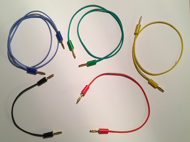
05/28/2020 at 16:18 • 0 commentsI started making the patch cables.
![]()
I found some relatively inexpensive 2 mm banana plugs at about 56 cents CDN each. The wire is silicon based and very flexible. From Amazon:
- 22 Gauge Electric Wire,Tinned Copper Wire Kit 22 AWG Flexible Silicone Wire(6 Different Colored 26 Feet spools) 600V Electronic Hook up Wire
- 20PCS Gold Plated Banana Plug for Speaker Wire, Home Theater, Wall Plates and More(Five Colors Choices)
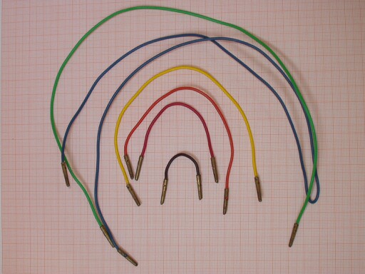
The cables are colored coded by length and are based to the original H-500 except black was substituted for brown and there are no orange cables. Here is what the original cables looked like (from http://www.so-much-stuff.com/pdp8/computerlab/computerlab.php):
![]()
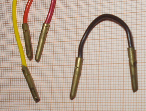
And here are the plugs that were used. If anyone knows what this type of plug is called and where one might find a supply I would be eternally grateful.
![]()
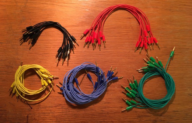
As I stated before the 2 mm banana plugs I'm using work great with the rivets so I'm fine with them for now.
![]()
Starting with 50 cables.
-
Credit Where Credit Is Due, Eh
05/28/2020 at 01:58 • 0 commentsI'm waiting for a lumber and stain order to be ready for "curbside pickup" so I can get started on the H-500 frame. In the mean time I thought I would jump ahead and make a very important part for the build.
![]()
On the back of each Computer Lab sold was a plaque with the model and serial number as seen above. What's important to me as a proud Canadian is that so far as I can determine all H-500s were Made In Canada. So I had to make sure that my reproduction had such a plaque.
![]()
Ready to go.
-
Plug Panel Wiring
05/21/2020 at 21:16 • 0 commentsWell I've started to wire up the Plug Panel. The circuits represented by logic symbols on the top of the board are implemented with a dozen 7400 series ICs underneath.
![]()
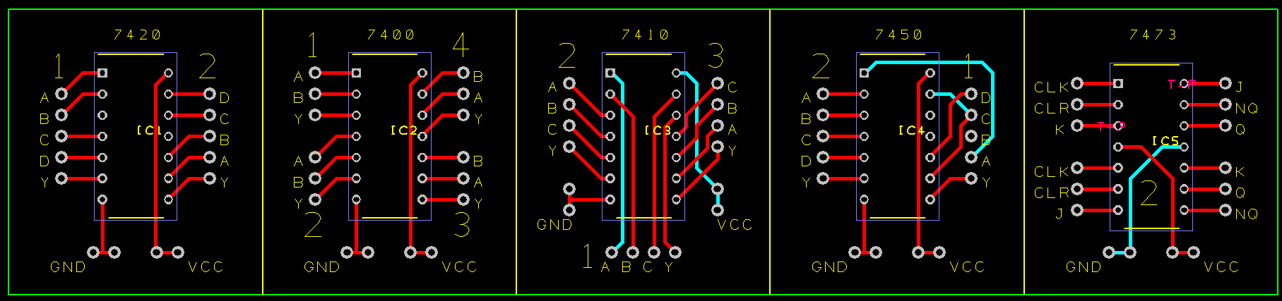
By looking at the logic symbols and using pictures of the wiring for the original H-500 I was able to determine the chips used:
- SN7400 - 2 Quadruple 2-Input Positive-NAND Gates
- SN7410 - 2 Triple 3-Input Positive-NAND Gates
- SN7420 - 2 Dual 4-Input Positive-NAND Gates
- SN7450 - 2 Dual AND-OR-Invert Gates
- SN7473 - 4 Dual J-K Flip-Flops with Clear
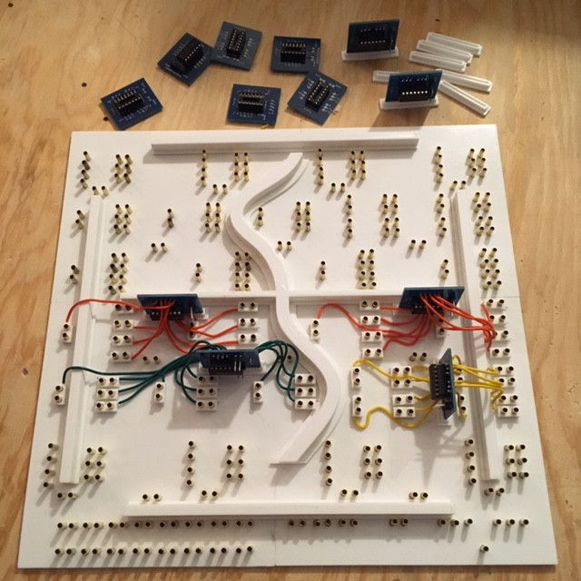
So this is what I have so far:
![]()
There's a few things to note here. First of all I decided to make my life a little easier by creating some breakout boards for the 74XX chips. My initial though was to just "dead-bug" the chips and solder the leads directly to the pins. It would have worked but the appeal of re-arranging the pin-outs to be more consistent with the layout of the panel, plus having a label on each pin won out. Here's the PCB:
![]()
I created a small base for the PCBs so that I could stand them upright since there was no room to lay them out.
My plan was to solder the wires coming from the break-out boards directly to the brass rivets. It turned out that this was a lot harder than I thought it would be. I really should have tested this much earlier in the process. I don't know if the brass was coated with something but the soldering iron had to be applied to the rivets way too long to get a good join. As a result the panel holes melted and got too large to hold the rivet securely in place. I needed a plan B.
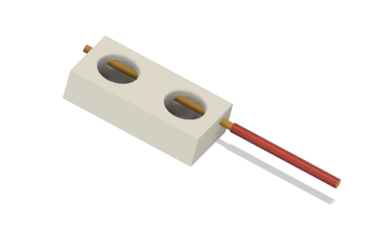
They say the necessity is the mother of invention, and I think the solution I came up with is actually better than if the soldering had worked. I made some mechanical "fittings" to securely attach the wires to the rivets:
![]()
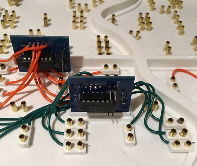
Just insert the wire into the horizontal hole and slide the fitting over a pair of rivets representing a circuit lead. These work great, are quick and easy to install, and actually reinforce the rivet's attachment to the panel. An additional benefit is that a whole PCB "circuit" can be removed from the panel should the need arise to troubleshoot. Here's a closer look.
![]()
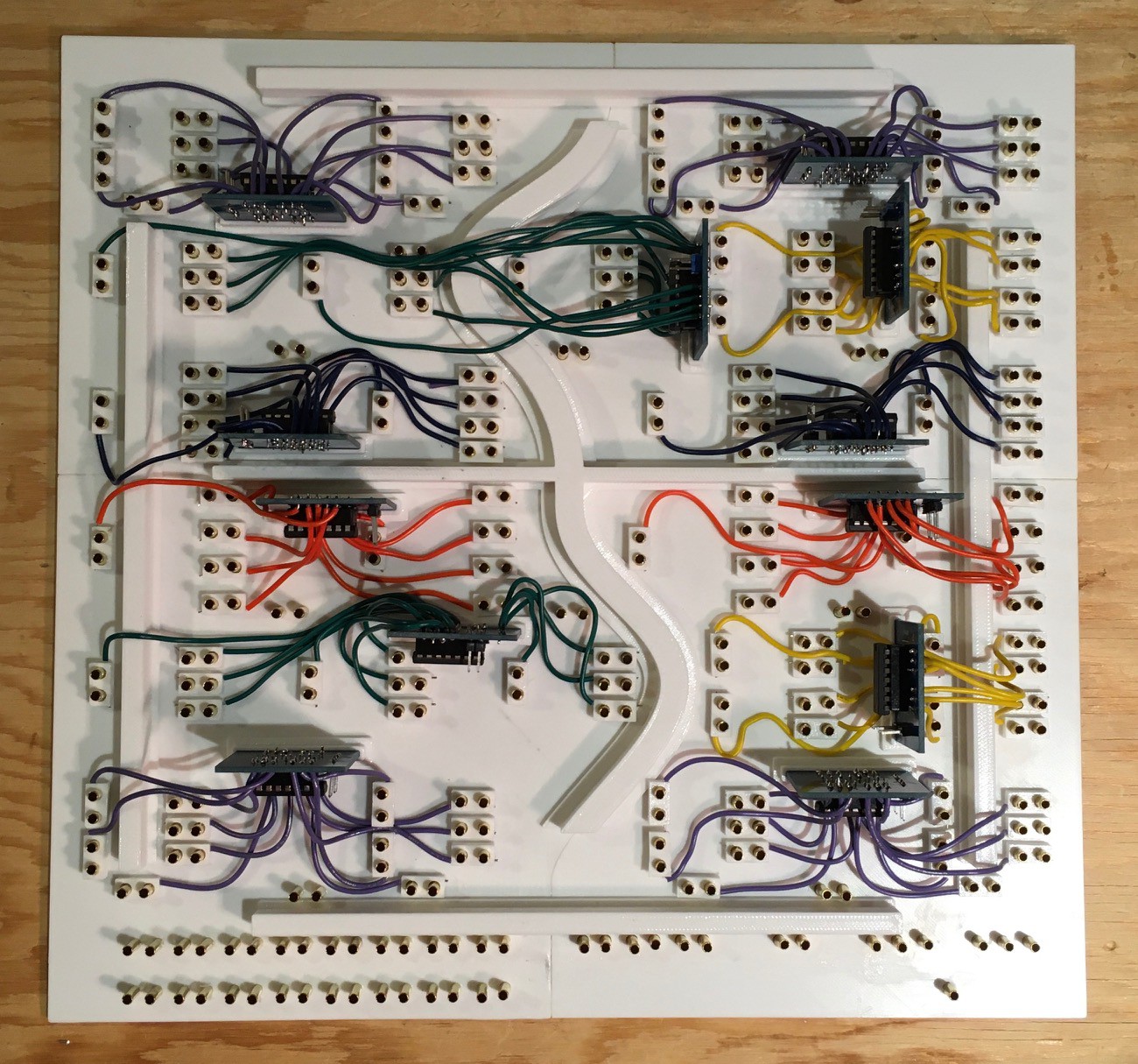
So with the bugs ironed out, it's time to finish the Plug Panel wiring.
![]()
And here you go. All the logic elements are now wired except for power which I'll run when I put all of the pieces together. Next I'll knock together a frame to mount everything in.
-
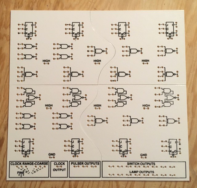
Plug Panel(s)
05/15/2020 at 15:17 • 0 commentsAfter a day and a bit of Fusion 360 modelling and twenty-six plus hours of printing, the Plug Panel "panels" are done.
![]()
Printed in multiple parts to accommodate my print bed, and the text is slightly larger than original to work at 3D printer resolutions, but a pretty good result I think.
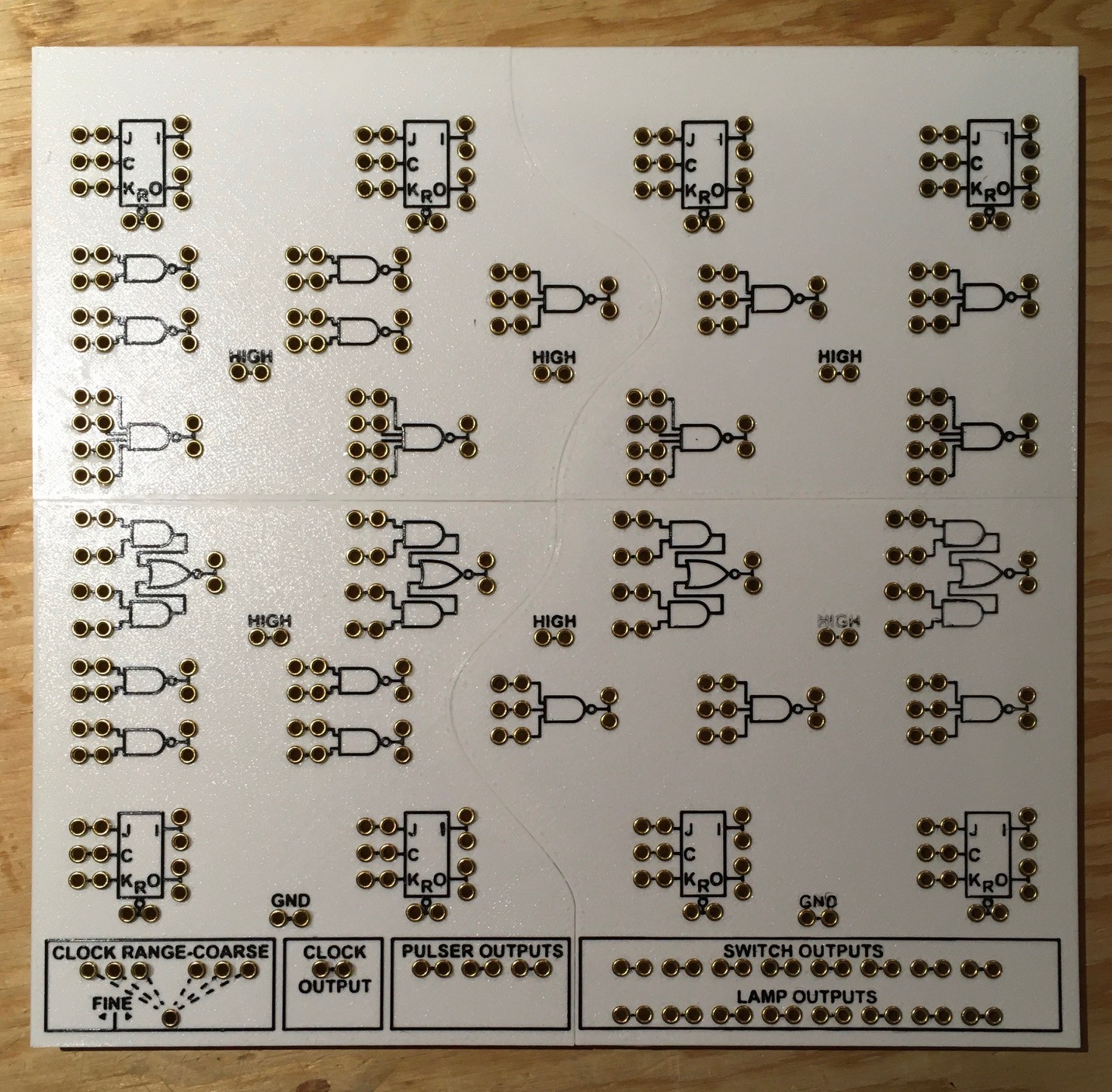
My big "discovery" for these panels was the "Hilbert Curve" option for the top layer.
![]()
I was unaware of this PrusaSlicer feature until now, and would certainly have used it in some of my other projects had I known about it (Minivac 601 and Digi-Comp II for sure). It produces a beautiful even matte finish unlike the somewhat "streaky" result I see with the default Rectilinear option. The downside is that Hilbert is quite a bit slower. It added an extra fourty minutes or so to each of the four panels I printed. Totally worth it in my books.
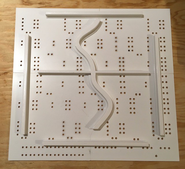
I glued the four panel pieces together. Since the Plug Panel itself needs to be pretty rigid to support the insertion and removal of the patch cables, I designed and printed some support beams and glued them to the underside.
![]()
Then it's just a simple matter of installing the 335 rivets onto the panel.
![]()
I had done a number of test to try to get the perfect hole size so that the rivets could be just pushed in with a nice friction fit. Unfortunately halfway through printing the panels I made a small adjustment to my first layer height. So in the end the two right panels worked as expected, but the ones on the left required a small dab of glue applied to the side of each rivet.
Time to start wiring these up.
DEC H-500 Computer Lab Reproduction
Reproduce the Digital Computer Lab H-500, a training tool from the late 60's aimed at teaching people the basics of logic circuits.


 Once dry I stained the boards then applied a few applications of clear coat. I was a little disappointed in the stain as I was expecting it to be a little lighter and redder like the original's "simulated teak". But given how long it took to get the stain I went ahead and used it.