MS-BOSS
-
An assembly job and first mistake found
05/04/2020 at 18:21 • 0 commentsHi,
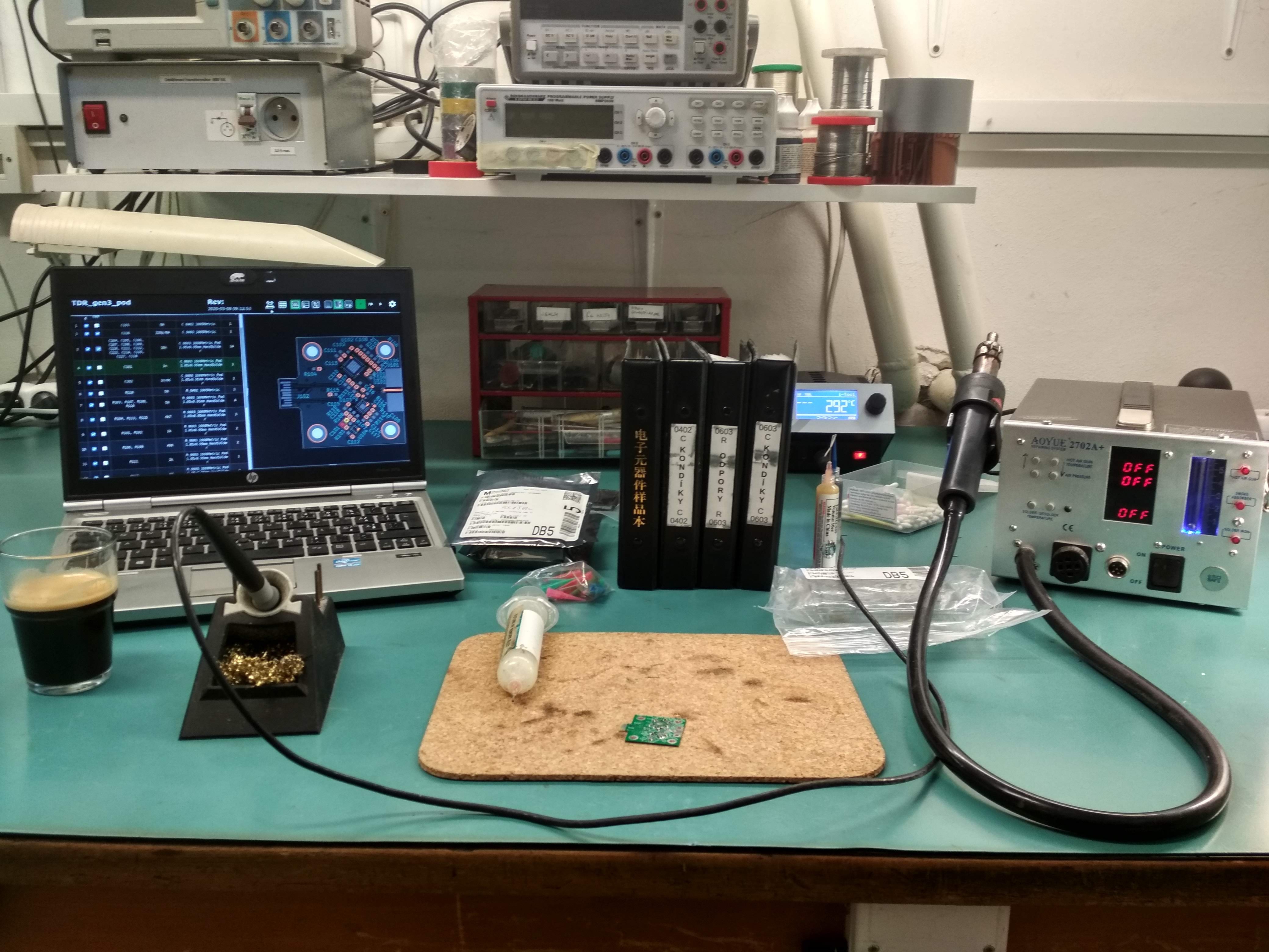
the board finally arrived. So I assembled it (very funny when it comes to QFNs) and now... well, nothing. I have to design the motherboard which will utilise this.
The first mistake I found while assembling it is that R110 shouldn't be there. It can be simply shorted together when hand-assembling. Somehow, I forgot there is internal 50Ohm termination inside the ADCMP582 since I have a design laying around which uses the ADCMP576 which has no fancy internal terminations and I got these two mixed up.
There is one trick I use always when assembling anything with QFN or QFP packages. First I solder all the solder pads on BOTH the PCB and the chip, then I apply solder paste (manual), then solder it using heat gun. Then, the failure rate gets under maybe 5%, most of which are shorts, unsoldered pads are gone. And removing the shorts is easy with soldering station and a bit of flux. However, since I didn't make anything in months, I forgot to use this trick and I was fighting with 1 unsoldered pad for 20 minutes...
Ready to solder once coffee is made.
![]() The problematic solder pad after being already solved (the leftmost one at the bottom row).
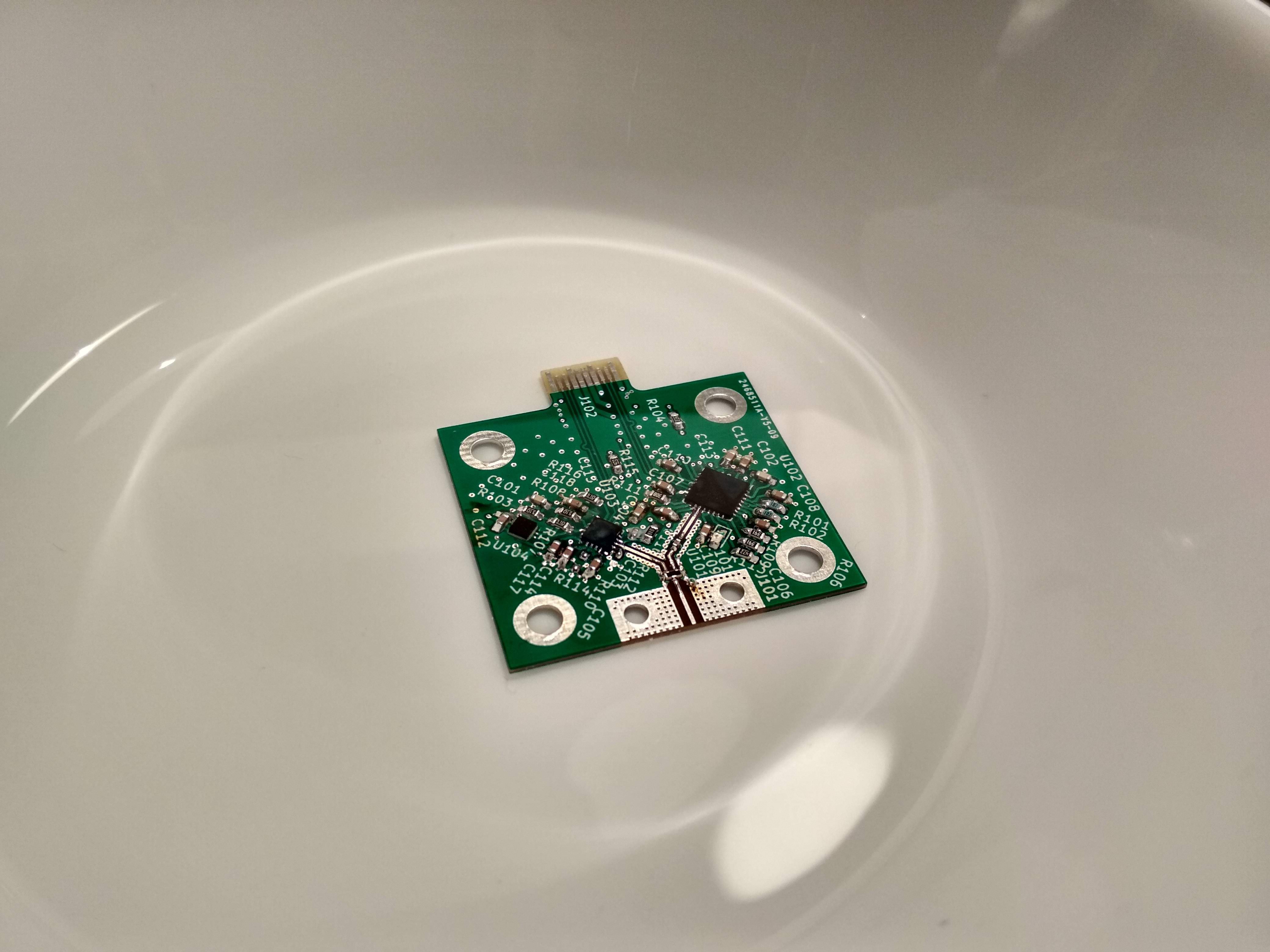
The problematic solder pad after being already solved (the leftmost one at the bottom row).![]() Cleaning in IPA in ultrasound cleaner:
Cleaning in IPA in ultrasound cleaner:![]()
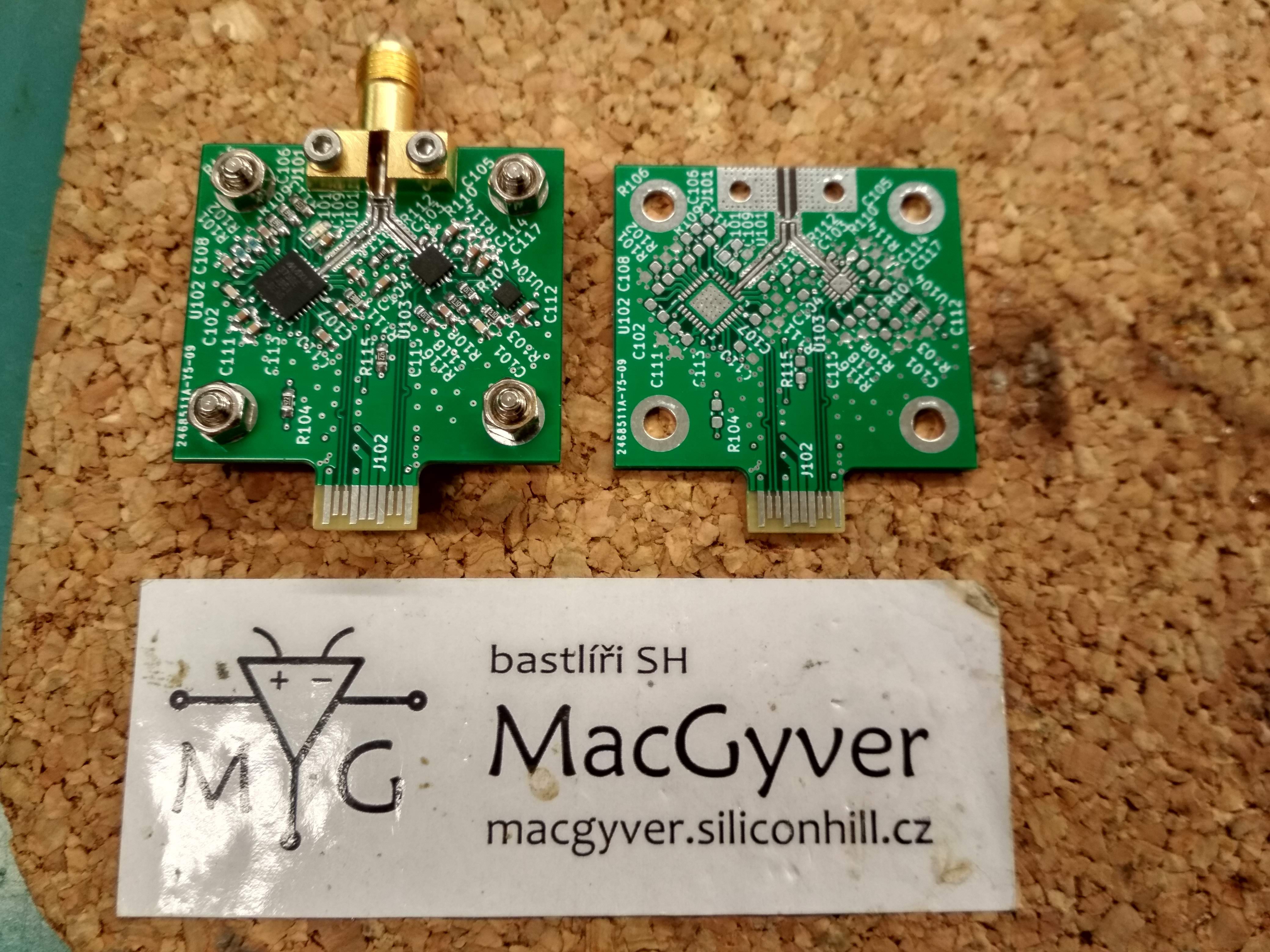
Clean board with soldered SMA connector (Rosenberger 32K243-40ML5, a middle-class connector). There is one trick to solder the central pin (believe me, it is to be soldered, the high-class SMAs which can be easily reused have a springy pin, not a stiff pin) - first position and center properly the SMA on the feed line (the centering is quite important), then slightly tighten the screws, position again, tighten and check whether it is correctly placed. Then, using a solder-paste applicator with narrow tip, apply a blob of paste on the pin and the feed line, then using the tip, try to make sure the paste is applied to both parts. Then, solder using heat gun.
![]()
That's all for today :)
-
First prototype was sent to the fab
03/08/2020 at 09:01 • 0 commentsHi folks,
I thought that after building my first standalone TDR (now called TDR-G2), I should build another one which would fix its issues. The main issues were:
- High noise floor
- Limited bandwidth (about 2 or 2.5 GHz)
- Limited risetime (around 270 ps)
- Slow sampling
- Very bad SMA connector and its footprint (almost completely correctable by SOL calibration)
- Many other issues caused by focus on low price
This time, the reflectometer will use ADCMP582 as one-bit sampler. Because its threshold will be controlled by a DAC, it will be possible to approximate the measured value. See Ted Yapo's oscilloscope (here on HaD) or loxodes's TDR (on GitHub) to see how well it works.
The pulse generator used is MAX3798 which can generate edges with 26ps risetime. Its modulation current can be set in 512 steps using internal DAC, thus allowing for setting the output RF power (if you have ever been measuring nonlinear devices with VNA, then you know how useful it can be). If the range proves to be too narrow, PE4306 or similar attenuator may be added later. This driver should be able to operate into 50 Ohm network without any funny impedance matching.
The used SMA connector is Rosenberger SMA, which is reasonably expensive nad should be more than good enough for this application.
The coplanar waveguides are not ideal, mostly due to the fact that there is one coplanar going from the connector, then transitioning into coplanar going into the splitter, then into the two coplanars going into the generator and sampler... It is impossible to reduce reflections to zero (also because I do not have nor can use any EM solver). However, the reflections should be small enough to be suppressable by SOL(T) calibration, which was already proven in the TDR-G2 where a cheap chinese SMA was used along with very bad footprint.
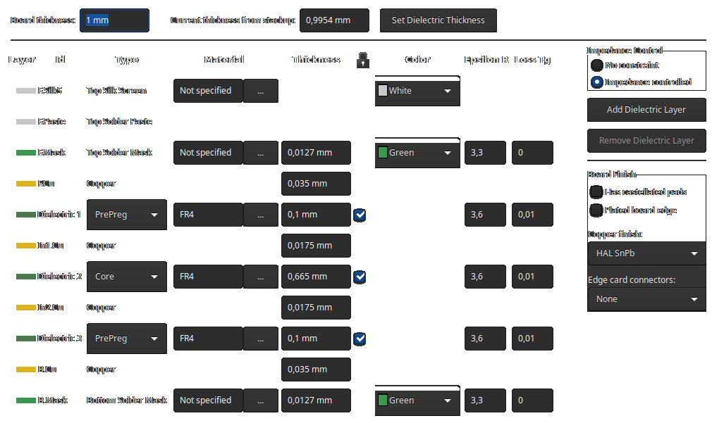
The board was sent to JLCPCB for manufacturing. The stackup is shown on image below. It is the Isola 7628 4-layer stackup as listed on JLCPCB website. Manufacturing cost for 10 pcs of 1 mm 4-layer impedance driven 7628 stackup board was $14 not including shipping fee. The board finish is HASL, because I do not prefer ENIG (see my microwave tips to see why it isn't good for microwave devices). And it makes the boards 3 times cheaper. The shipping fee was $7 for China post.
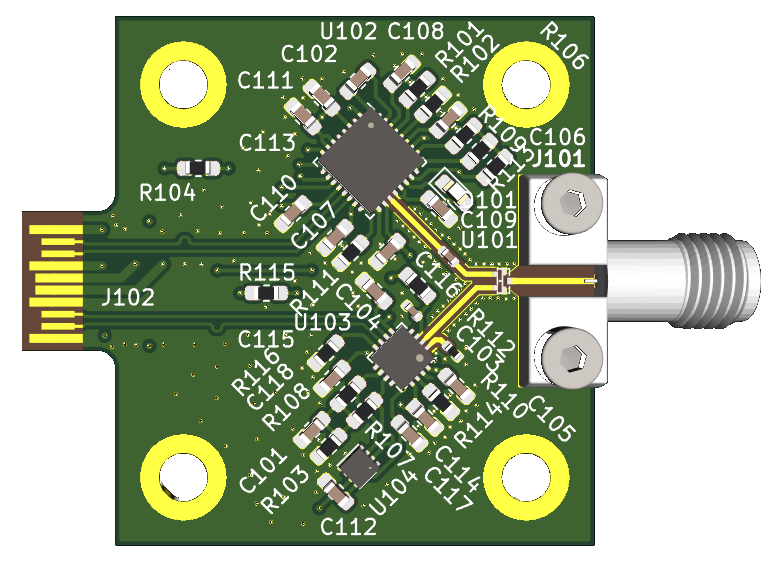
The board should fit into SFP/SFP+ connector. Its dimensions are 35x37.5 mm, thus not fitting into standard cage. Sorry for that, but it was not my intention to fit int othe cage. Mounting holes are for M3 screws.
Sidenote: You may be interested in seeing this application note.
![]()
![]()
ISOLA 7628 0.2 mm stackup coplanar (Er = 4.3):
W = 0.315 mm
G = 0.14 mmor
W = 0.365 mm
G = 0.25 mmISOLA 2313 0.1 mm stackup coplanar (Er = 3.64):
W = 0.21 mm
G = 0.162 mm
TDR sampler/pulse generator "pod" (TDR-G3)
A "pod" containing fast pulse generator and sampler. This "pod" should serve as the basis of TDR-G3. The other part will be the main board.
 The problematic solder pad after being already solved (the leftmost one at the bottom row).
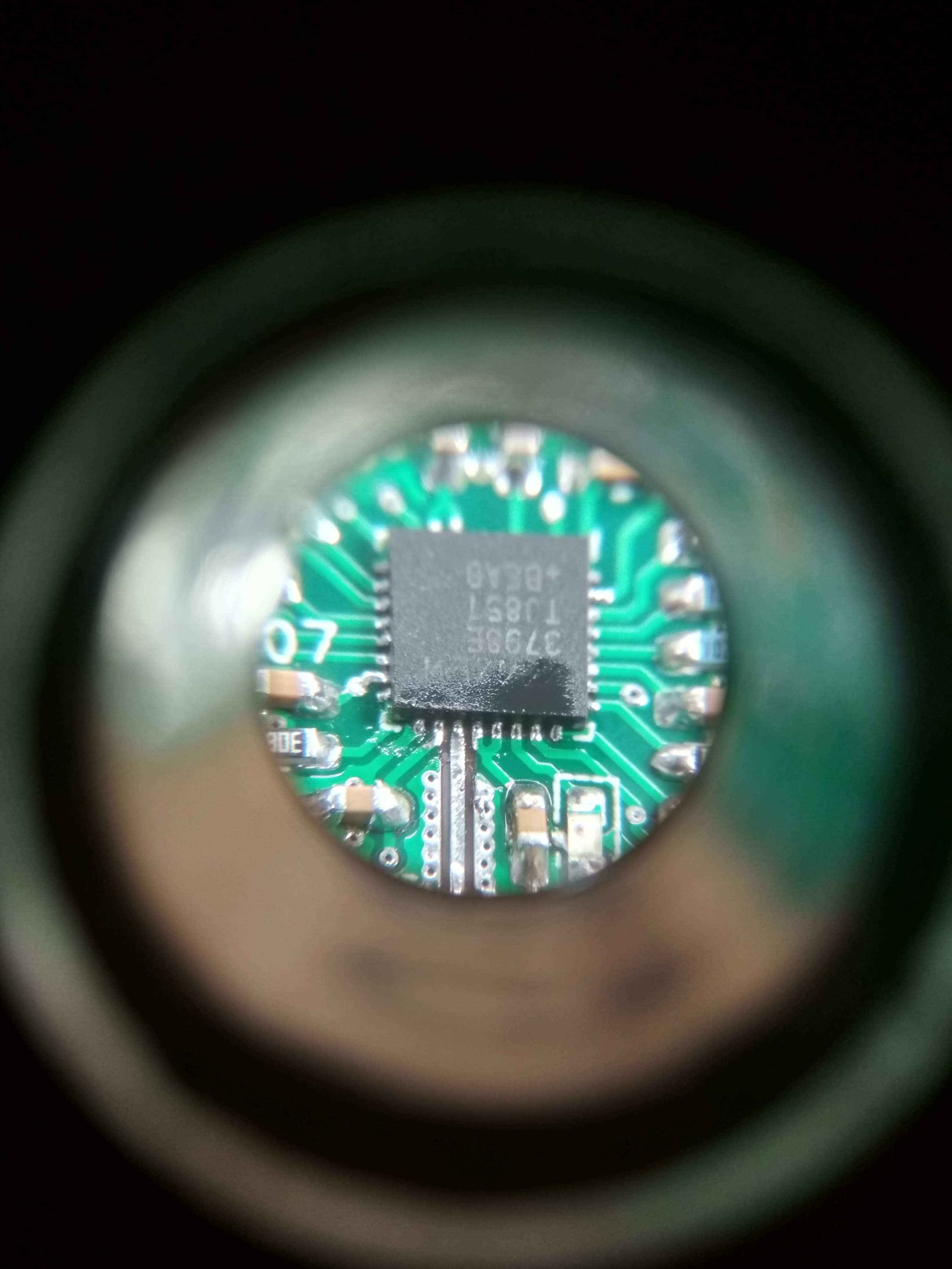 Cleaning in IPA in ultrasound cleaner: