Close
0%
0%

3D LED cylinder - remix of makeTVee

3D LED cylinder - remix of makeTVee

Similar projects worth following
3D LED Cylinder made using 3D printing, similar to makeTVee.

This is made under MIT License

Background

This is a 3D LED matrix cylinder inspired by makeTVee and adapted for 3D printing. The concept is that the matrix grid is printed flat and rolled up into a cylinder.  The LED's are installed and then the sky is the limit on what you can do!

The Inspiration - makeTVee

This cylindrical LED matrix from makeTVee is where it all started.  He uses laser cut card board for the sections.  

https://hackaday.io/project/162035-led-matrix-cylinder


I don't have access to a laser cutter but wanted a matrix, so I adapted his design to use 3D printing for the mechanical and ESP32-based WiFi connected Feather board (Adafruit Huzzah32) as the controller.

Bill of Materials
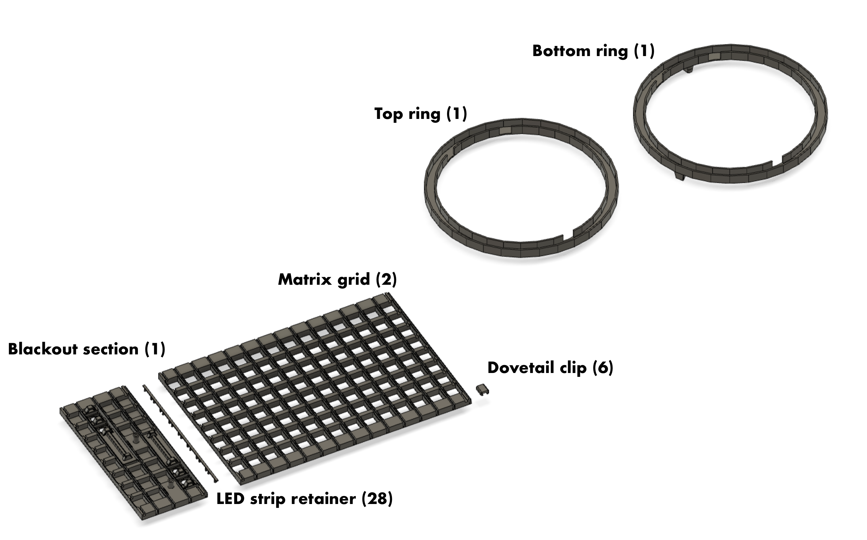
3D printed pieces

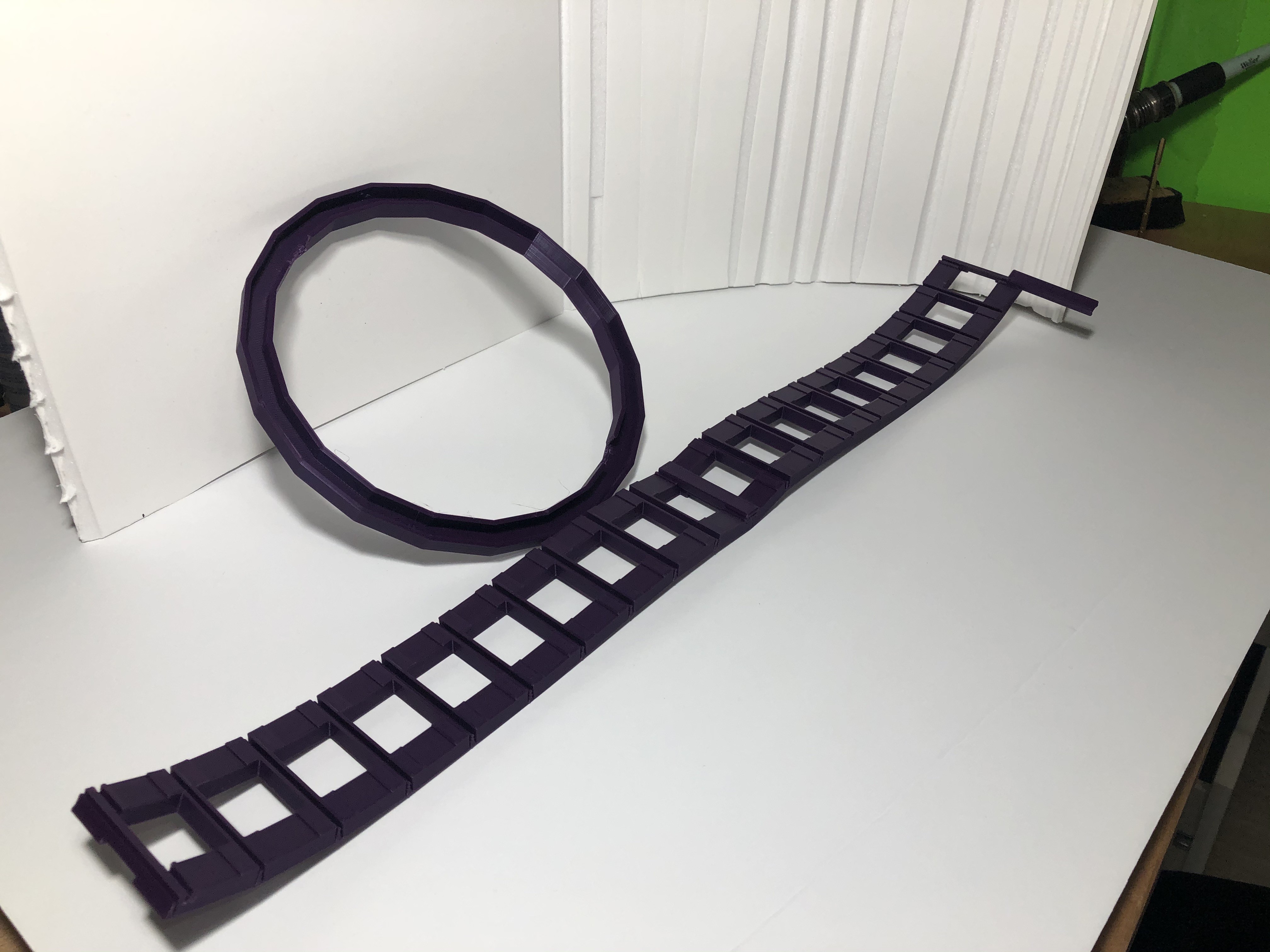
  • Matrix grid (2 large pieces)
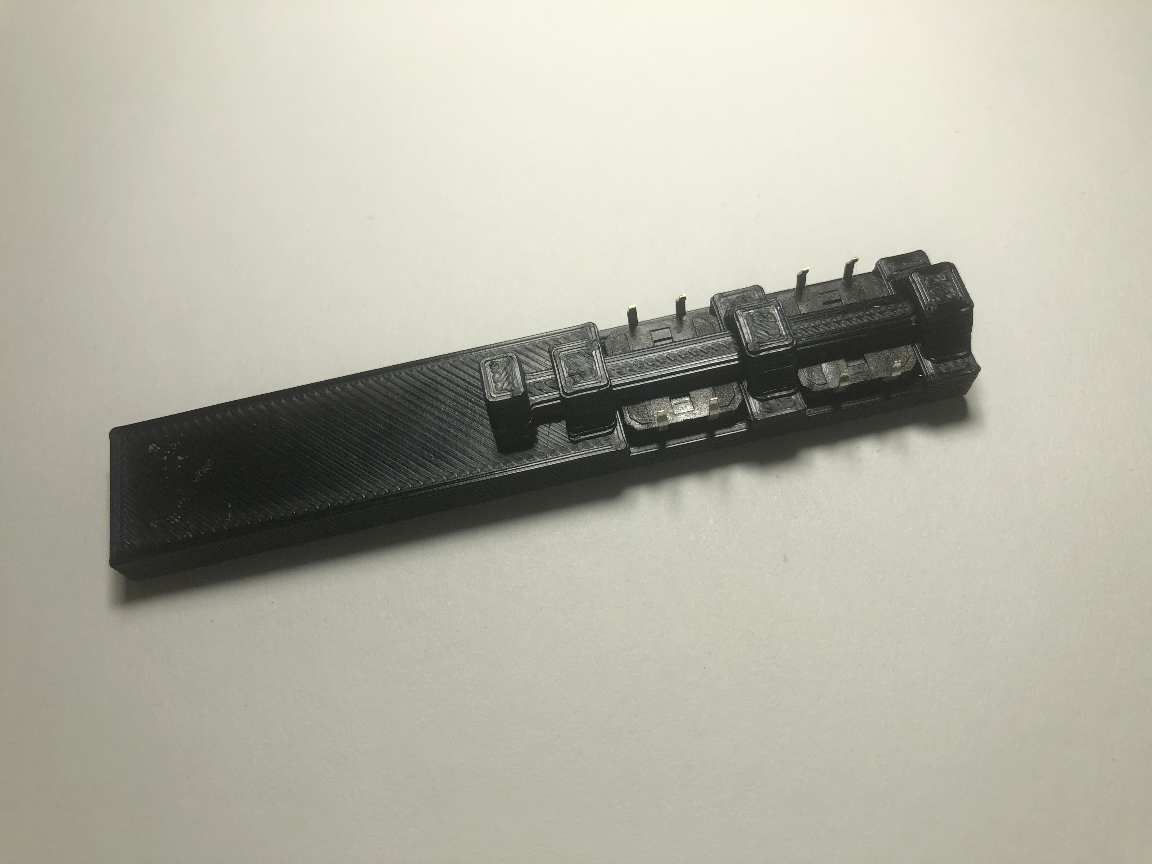
  • Blackout section with four button holes and mounting location for breadboard
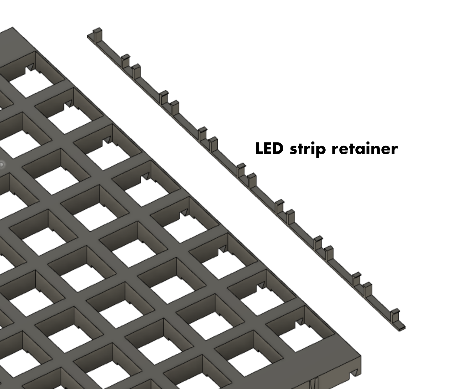
  • LED strip retainers (28 quantity, probably overkill)
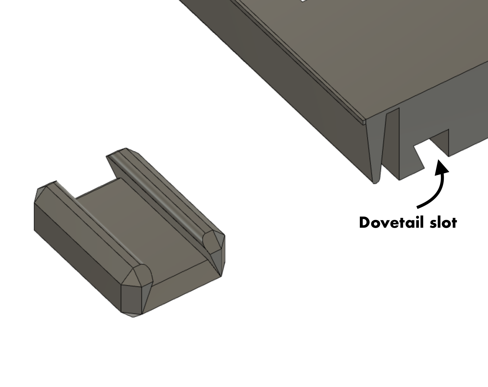
  • Dovetail clip - Connect the sections together in dovetail slots (6 quantity)
  • Top ring (no feet)
  • Bottom ring (with feet, or use no feet if using a wooden frame)
  • (optional) Wood circle for top and bottom and a way to hold them on.


Electronics components

  • WS2812 LED strip, 60 LEDs per meter, 5 meters, cut into 28 LED strips (8 quantity)
  • Hookup wire
  • Tactile buttons, 12mm (4 quantity)
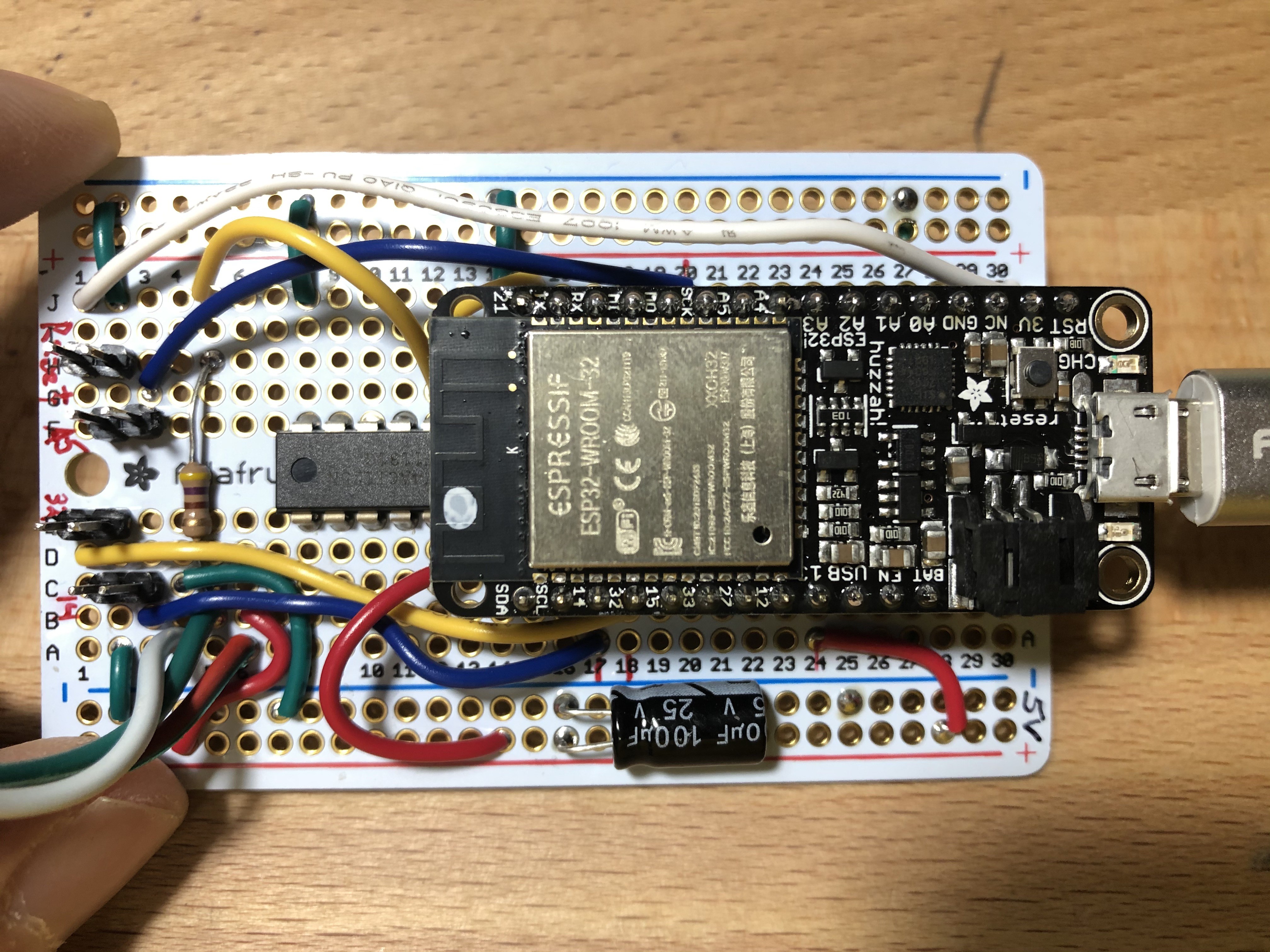
  • Adafruit Feather Huzzah32 (ESP32) - Soldered directly to protoboard or onto removable headers
  • Level shifter - part number 74AHCT125 (may be optional but I used it anyway)
  • 470 Ohm resistor - for connection to LED data line
  • Half sized protoboard
  • Miscellaneous wire, solder and flux
  • 100 uF, 25V electrolytic capacitors - Across 5V USB bus and across the 3.3V (2 quantity)
  • USB cable


Electrical connections to the Feather Huzzah32 (ESP32)

  • LED signal - Pin 21 - connects to LED strip data input through the Level Shifter
  • Button A - Pin 14
  • Button B - Pin 32
  • Button C - Pin A5
  • Reset - RESET 

Mechanical Design - Final

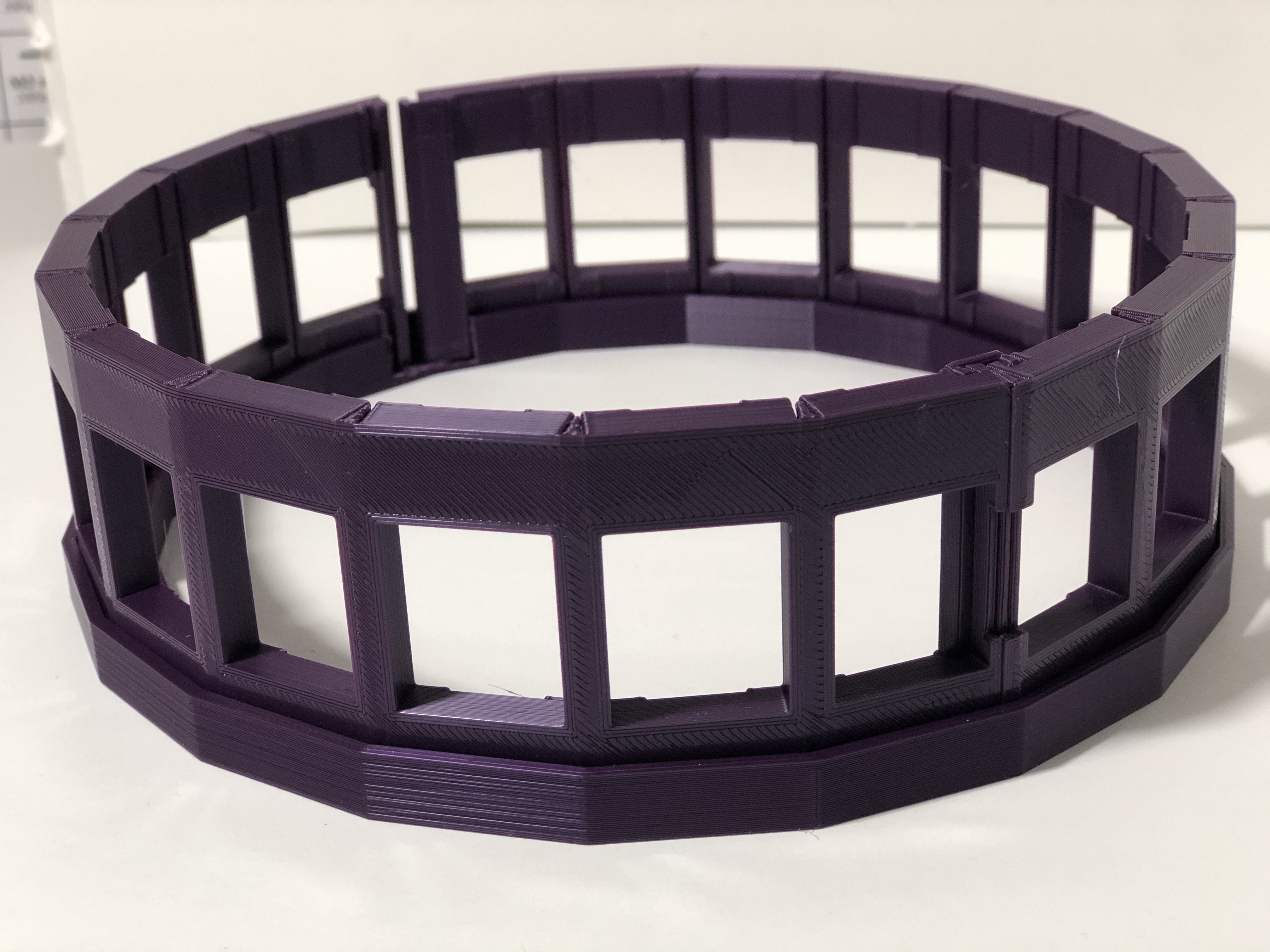
The LED matrix holder is designed to print flat on the 3D printer and then roll up into the cylindrical shape.

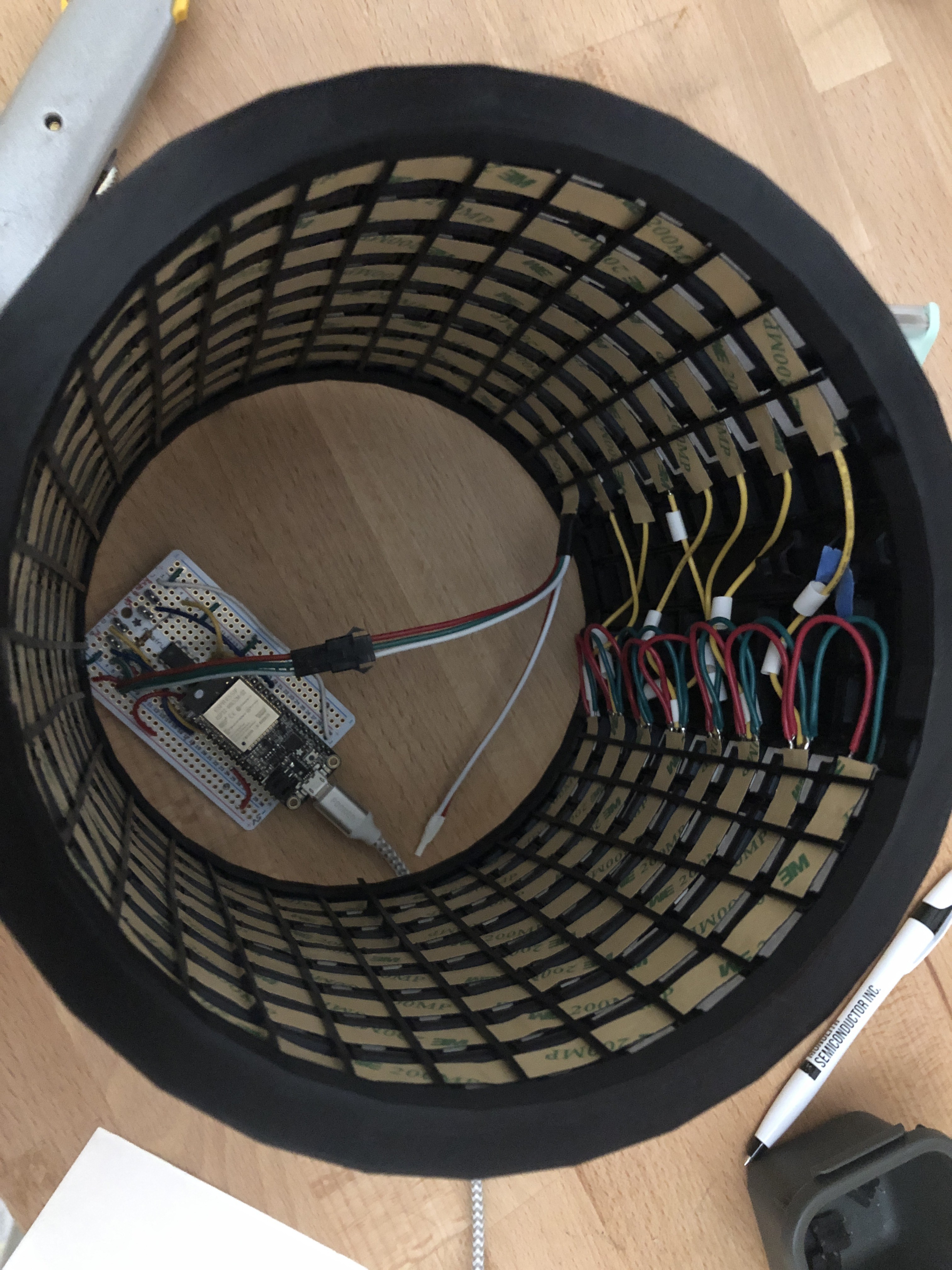
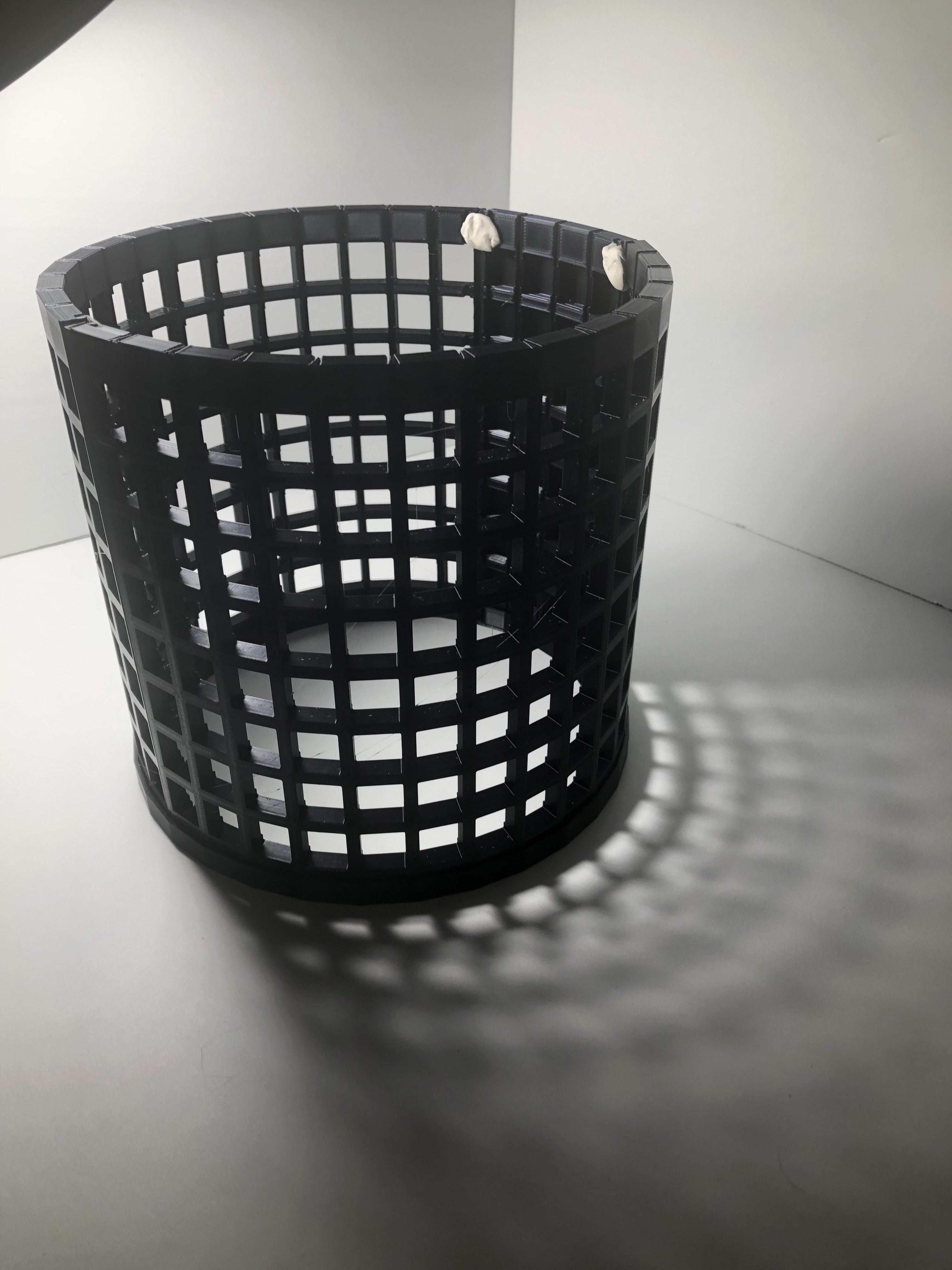
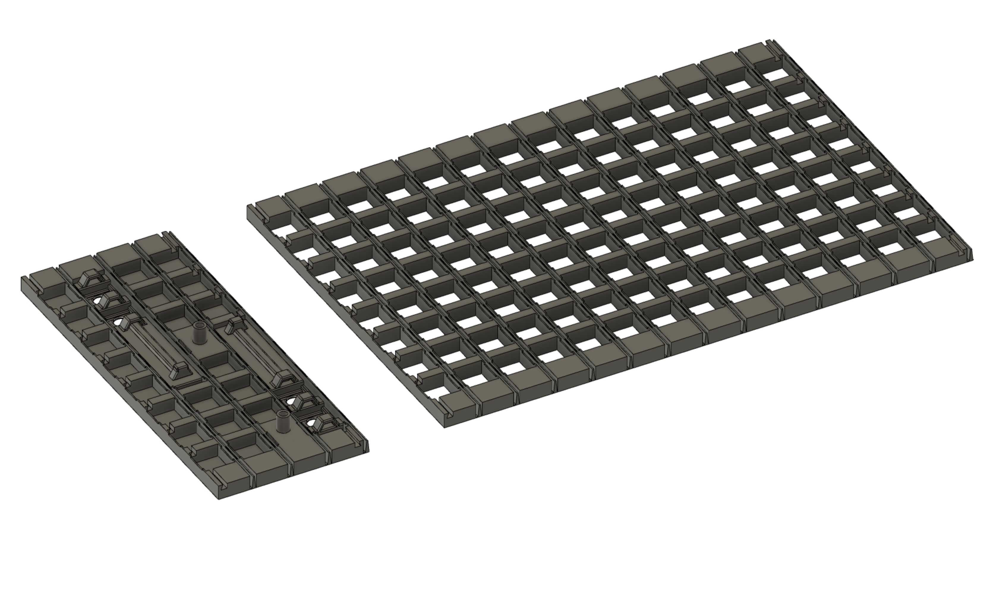
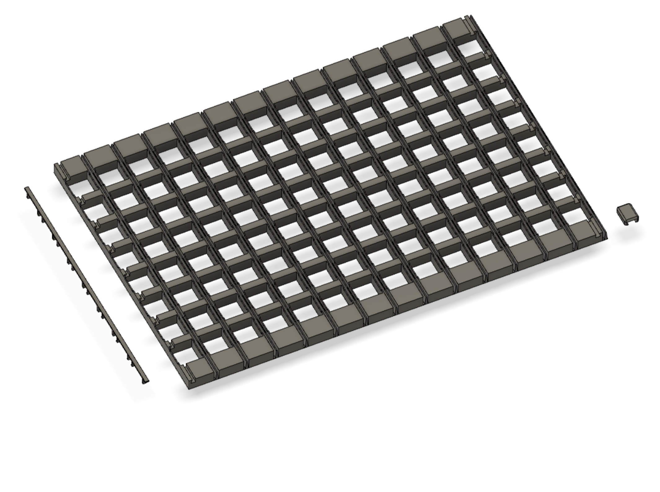
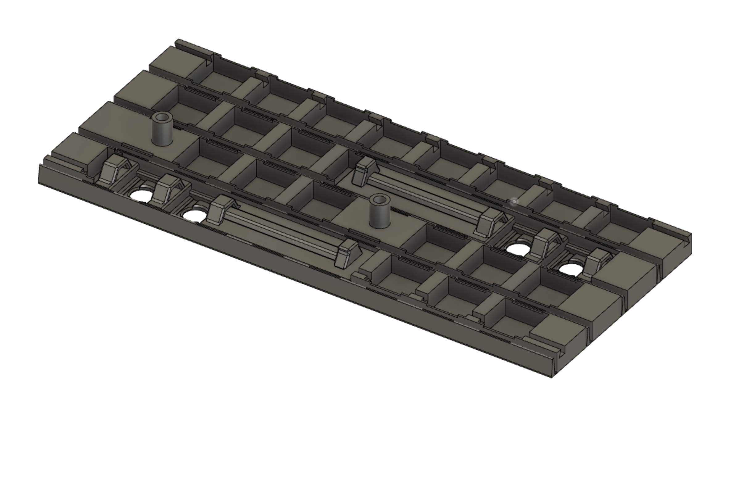
The largest panel is designed to fit onto a 12x12 inch bed (Creality CR-10S in my case).  The large panel accommodates an 8x14 array of LEDs (using 60 LEDs/m strips).  Two of the matrix sections are required to make the 8x28 LED array.  The LED strips fit into recesses in the matrix.  The LED strips run horizontal with 28 LEDs in each strip.  In contrast to makeTVee, I ran my strips horizontally to reduce the number of connections as well as to simplify hiding the wiring.

A "blackout" section (8x4 worth of LED) is provided for holding the buttoms and the protoboard.  So, connecting these three sections provides an effective 32 sided polygon worth of sections.
The LED matrix is completed using the LED strip retainers and the dovetail clips.
The sections are butted together and joined using the dovetail clips in the dovetail slots. 
After installing the LEDs into the slots in the matrix, each of the 28 sections receives an LED strip retainer to keep the LED strip in place in its respective slot.  These retainers slighly flex to maintain friction on the matrix edges.
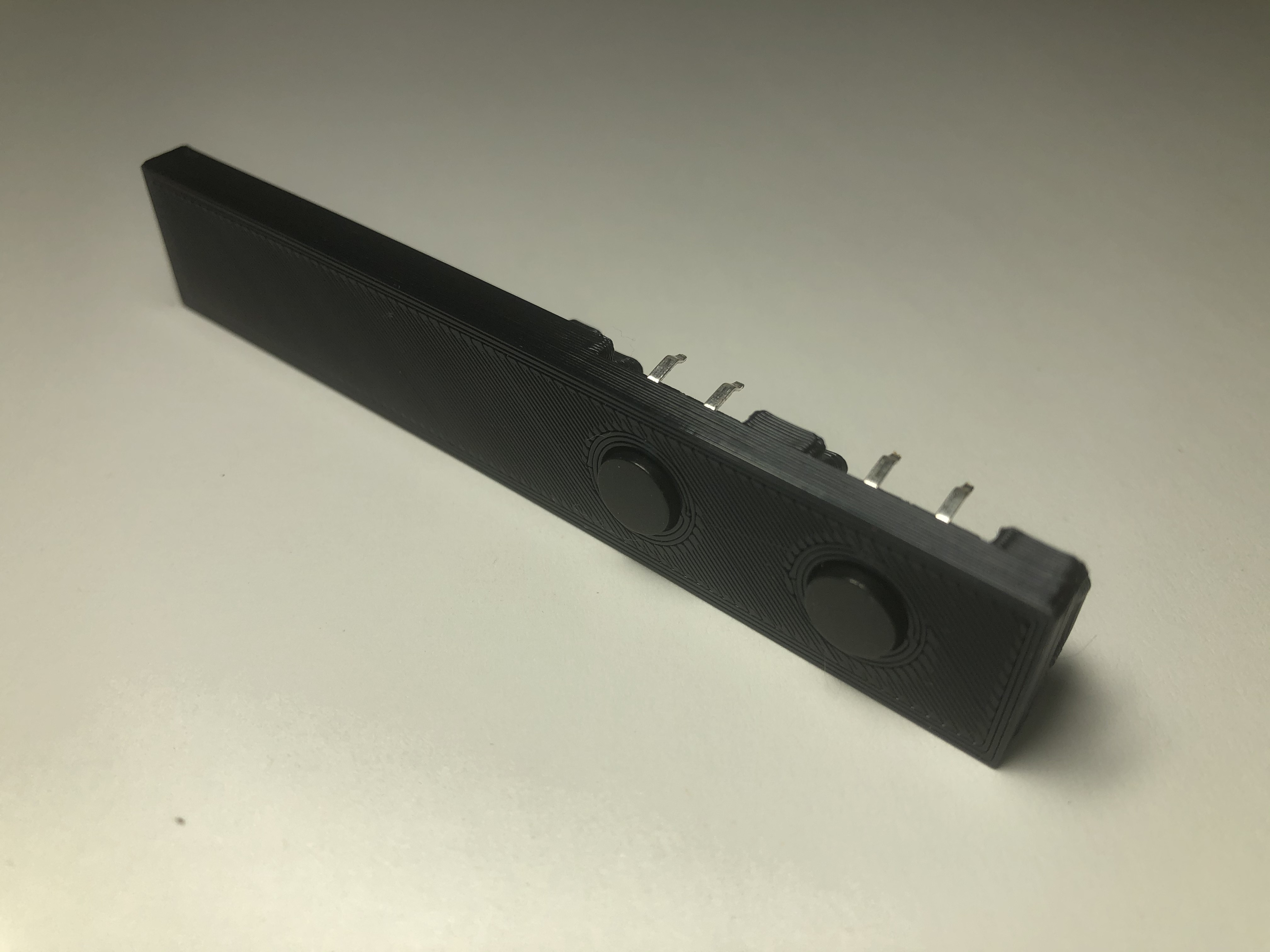
The blackout section provides room for 4 buttons and M3 bolt through holes for mounting the prototype board.
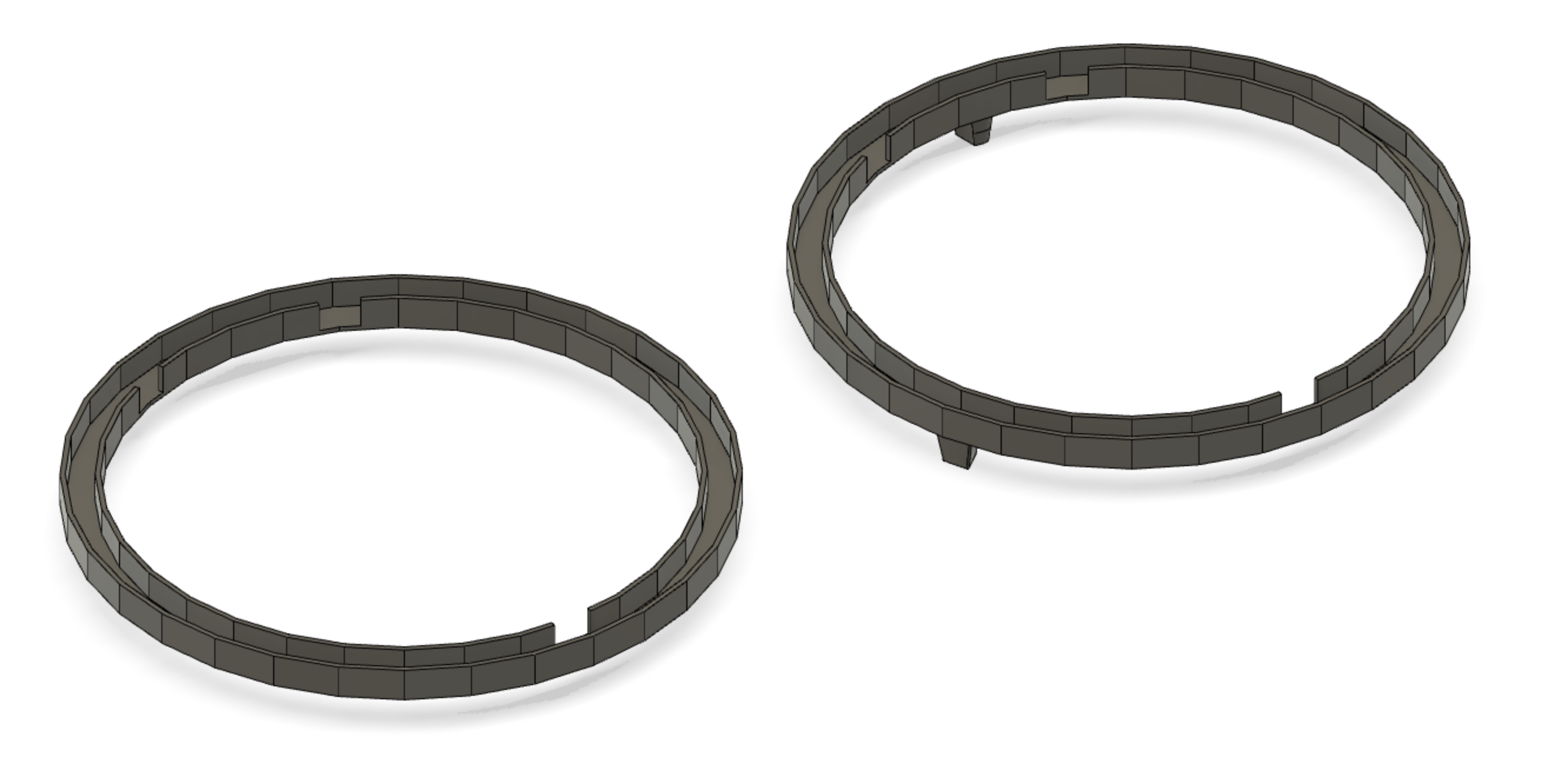
The top ring and bottom ring (with feet) have cutouts to receive the dovetail clips between the matrix sections.
Note: The USB cable snakes under the bottom ring feet and into the Feather's USB port.  There's probably a cleaner way of doing this to have the USB port accessible from the blackout panel, but I didn't bother with it.

Test Program (Arduino)

Here is a test program that shows a rainbow and then goes through red, green, blue to check out all the LEDs.  Also you can check the button operation using the serial console.

This test program was based on Adafruit's NeoPixel matrix code but modified to run on the ESP32 by using the NeoPixelBrightnessBus library by Makuna....

Read more »

SimpleGifAnimViewer.zip

This Arduino sketch allows you to load and play 8x28 pixel animated GIFs onto the cylinder. See the Updated entitlend "Gotta Make You Understand" on additonal steps to get the GIFs loaded onto the ESP32 filesystem.

Zip Archive - 103.80 kB - 03/28/2020 at 03:11

Download

Pasted Graphic 5.png

Portable Network Graphics (PNG) - 1.40 MB - 03/10/2020 at 20:09

Preview

IMG_5922.jpeg

JPEG Image - 1.35 MB - 03/10/2020 at 20:09

Preview

  • Gotta Make You Understand

    kmatch9803/28/2020 at 03:10 0 comments

    Special message

    When delivering the cylinder to the programming team, I included a special message. 

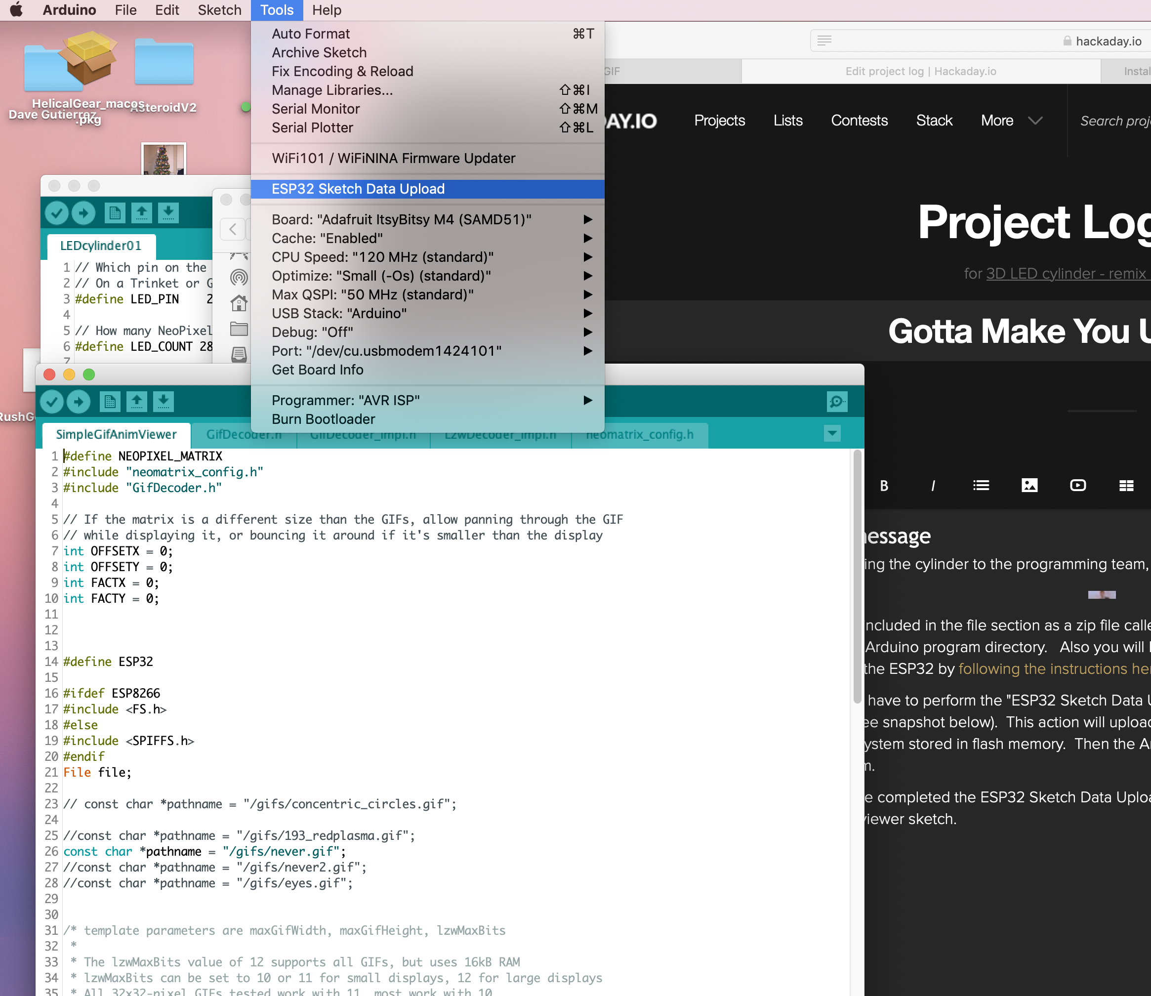
    The Arduino sketch code is included in the file section as a zip file called "SimpleGifAnimViewer.zip".  Unpack this into your Arduino program directory.   Also you will have to setup Arduino to upload files to to SPIFFs on the ESP32 by following the instructions here.

    Then you will have to perform the "ESP32 Sketch Data Upload" to get the files onto the SPIFFs file system (see snapshot below).  This action will upload the files in the sketch's "data" subfolder onto the ESP32's file system stored in flash memory.  Then the Arduino script can open these files from the file system.

    After you have completed the ESP32 Sketch Data Upload, then you can compile and run the Arduino GIF viewer sketch (SimpleGifAnimViewer.ino).

    If you want to add your own GIF file, use a utility like ezgif.com to crop and shrink them down to 8x28 pixels.  With so few pixels, you will have to use your imagination, but clearly you guys have mad skills at decipering GIFs.

  • The Cylinder Lives!

    kmatch9803/21/2020 at 02:00 0 comments


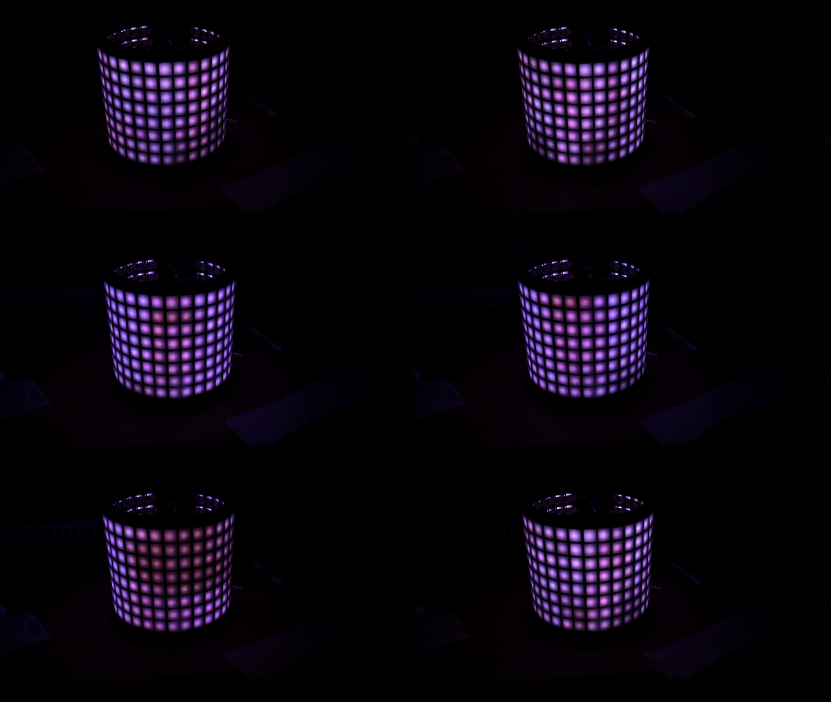
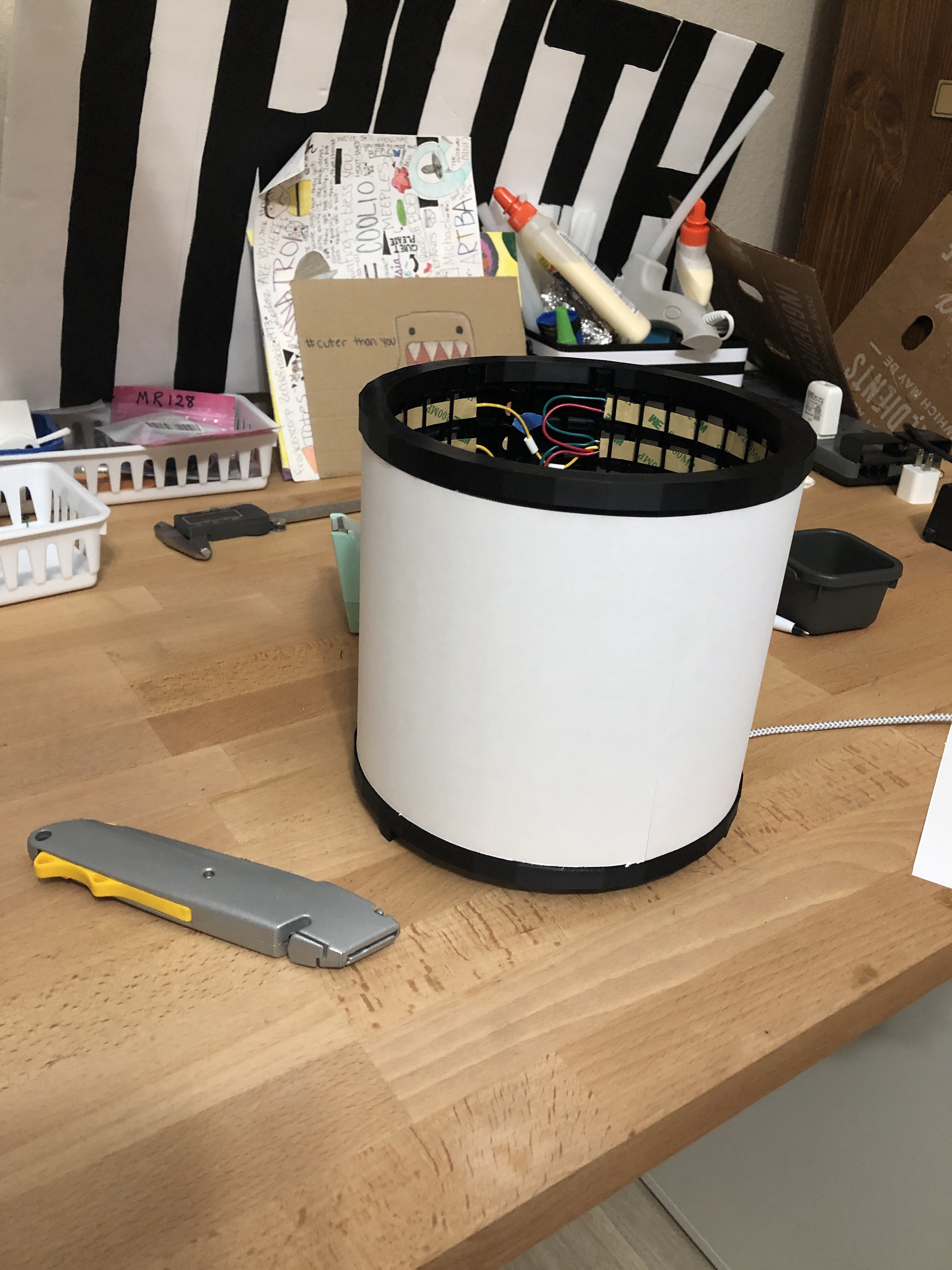
    I got the LED strips soldered and inserted into the cylinder.  I printed retainer strips to keep the LEDs in their slots.  It’s now wired up to the Adafruit Feather Huzzah32 and now running a rainbow trial. 

    I taped two sheets of paper to make the diffuser. Not perfect but pretty effective as a diffuser. 


    I just need to wire up the buttons (awaiting delivery of the wires and connectors to connect to the two-pin headers include the breadboard to simplify disassembly/reassembly). 

  • Mechanical improvements. The Matrix has risen!

    kmatch9803/17/2020 at 02:40 0 comments

    I confirmed the pitch on the LEDs and printed out the two large arrays. Right now there are 8x28 LEDs in the array and 8x4 blackout spots in the back for a couple of buttons and the DC power input.  I have printed a segmented cylinder base ring with a slot to hold the flexed matrix segments.  Also, I will use some dovetail clips to hold the sections firmly together (right now the sections are held with gummy funk in the photo). 

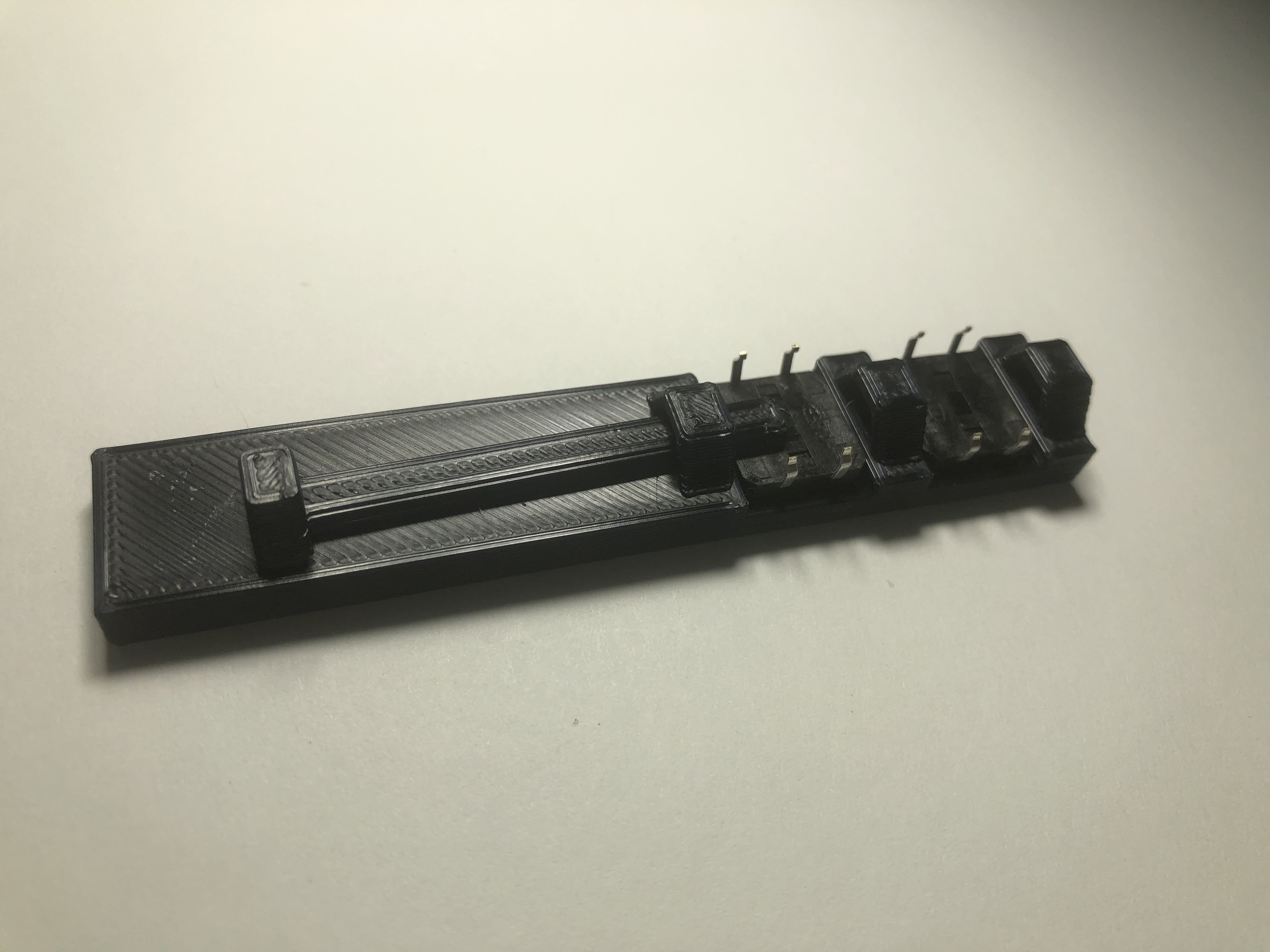
    Also I mocked up the button connector. Inspired by ClockSpring , the switch holder has a print in place button retention slider. 

  • Mechanical Design - Round 2

    kmatch9803/12/2020 at 23:46 0 comments

    I printed another trial for the LED ring.  The outer ring prints flat in two strips.  These strips are then folded int a rough right and the sections connect using dovetail clips.  

    Also, there is a topper ring to hold the whole thing in a roughly cylindrical shape.  I need to adjust the size of the ring so that the strips fit perfectly.  

    I ordered some 60 LED/meter strips (5 meters long).  For 60 LEDs/meter, the LED repetition pitch is 16.54 mm. That will give 300 LEDs to make into an array.  I'm currently thinking about an 8x32 array to make a satisfying 8-bit amount (256 LEDs).  

    Also, I will add 2-3 columns that are blacked out to hide the wires that interconnect the rows of LED strips.  That will make effectively 35 colums.  I am considering running the LED strips the long way (32 LEDs per strip) so that I will only have to wire up 8 ends.  That will give a ring approximately 222mm in diameter (about 9 inches).  More mechanical design is required to verify.

    Things to figure out:

    1.  When rolling up the strip into a ring, need to keep the final size of 16.54mm pitch on the inside of the ring.

    2.  How to keep the LED strips in place? 

      - Hot glue (bleh!)

      - Springy clips:  How to keep them in place without coming off

      - Clips that are then welded on with the soldering iron.  I like this idea, but repairability will be low.  Maybe that's a positive feature.

View all 4 project logs

Enjoy this project?

Share

Discussions

Excel Orange wrote 06/05/2023 at 15:08 point

This looks absolutely incrdible! I love the LED lights. - https://drivewayresurfacingwollongong/

  Are you sure? yes | no

Peter wrote 12/07/2022 at 03:42 point

LED lights are awesome, love how you built this! Will work towards building something like this over xmas with the kids. <a href="https://drivewayresurfacingwollongong/">Concrete sealing Wollongong</a>

  Are you sure? yes | no

wifacaw230 wrote 08/23/2022 at 14:42 point

Thank you for sharing this amazing post. keep up the great work. https://concreterswollongong.com/  

  Are you sure? yes | no

casseverhart13 wrote 05/22/2022 at 13:55 point

The components you used for this beautiful but simple light was awesome! Tiling Edmonton

  Are you sure? yes | no

Similar Projects

Does this project spark your interest?

Become a member to follow this project and never miss any updates