 Grant Stankaitis
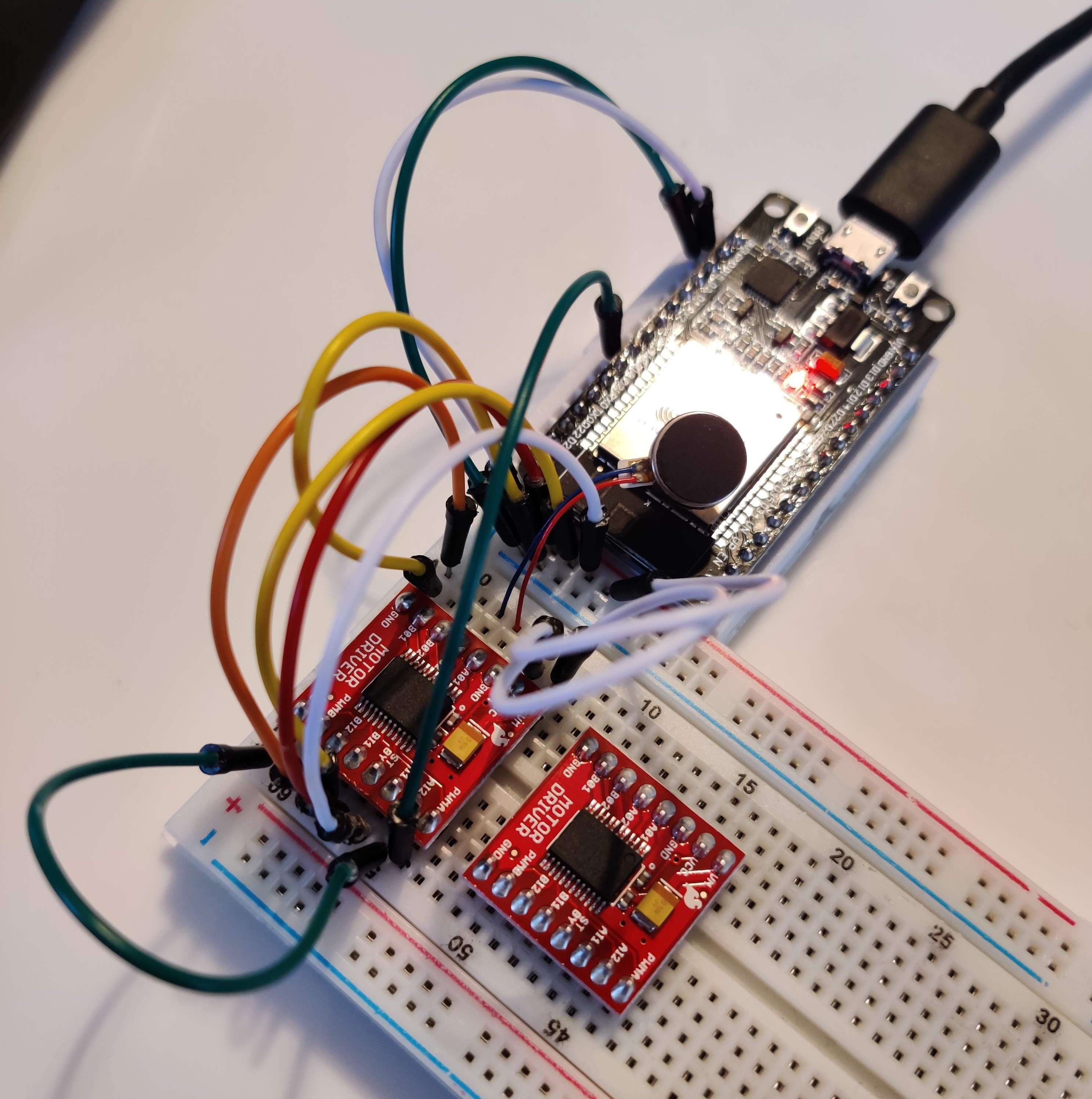
Today I worked on testing the PWM motor functionality of the system using the Sparkfun TB6612FNG motor drivers. As you can see in the picture below, I followed the schematic that the previous students used. To simplify things, I wrote out what the pins should be connected to.
- VCC, VM, BIN1, STBY, AIN1 ----> +3.3v
- GND, BIN2, AIN2 ----> GND
- A01, A02 ----> Motor 1 (I wired the red wire to A01, but I don't think it matters?)
- B01, B02 ----> Motor 2
- PWMA ----> ESP32 pin outputting PWM signal (PWMA corresponds to A01, A02/motor1)
- PWMB ----> ESP32 pin outputting PWM signal (PWMB corresponds to B01, B02/motor2)
Below is the code that I used to test the motor:
import time
import machine
from machine import Pin

motor = machine.PWM(Pin(18))
motor.freq(1000)

while True: # On for 2 seconds, off for 2 seconds
  motor.duty(341) # Input different values here to test
  time.sleep(2)
  motor.duty(0)
  time.sleep(2)
My next test will be to wire up all of the motors and expand my program to sequentially send a signal to each motor.
Discussions
Become a Hackaday.io Member
Create an account to leave a comment. Already have an account? Log In.