 Jacques Gagnon
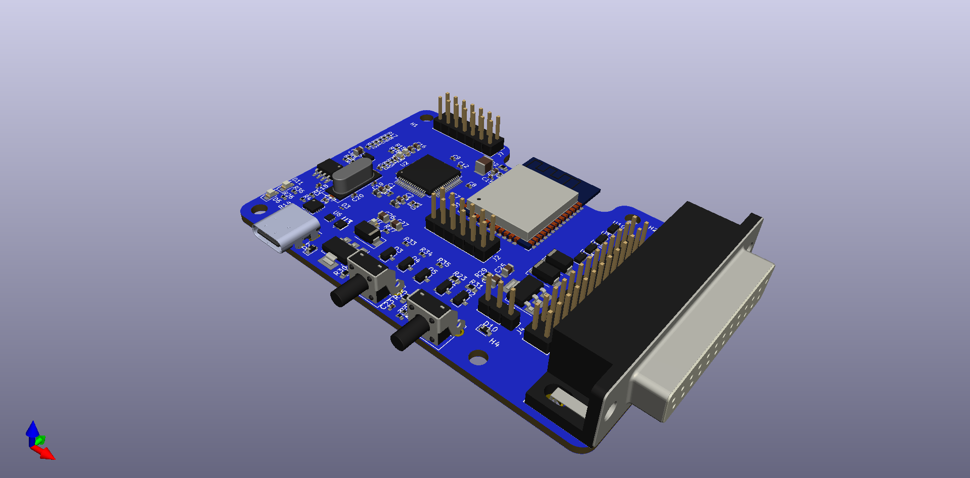
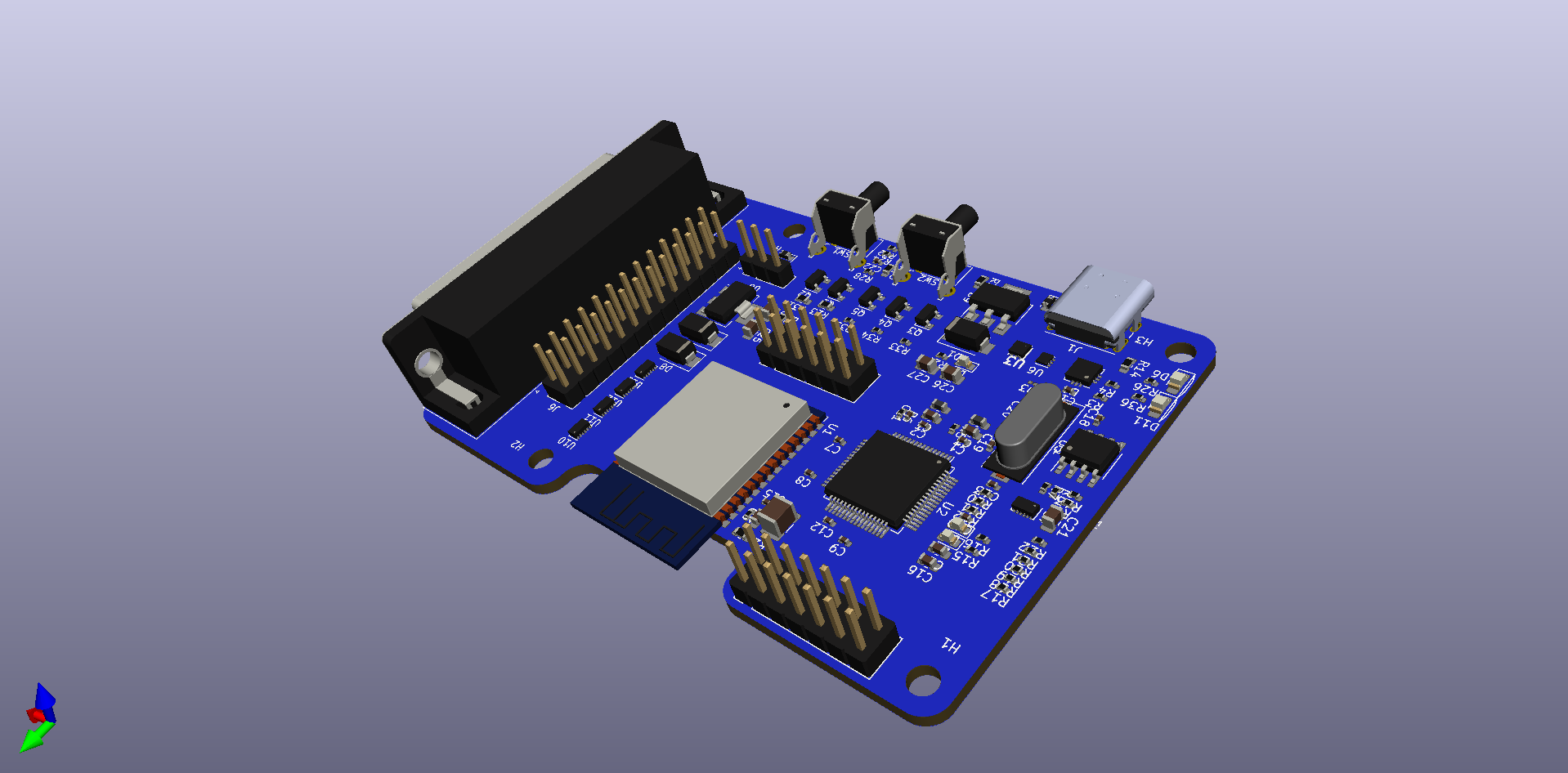
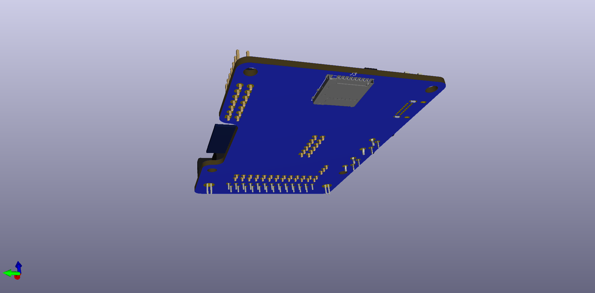
Still progressing on the PCB design. Pretty much placed every part around their final location. Some tweak will happen once I route the board for sure. Not finish yet but it look pretty cool already :) .
I've change the pin assignment for a few adapter cables to make things a bit more consistent and also allow the use of the BOOT switch by the firmware.
- Genesis/Saturn: Move TR-2 to pin GPIO16 (Keep IO0 for BOOT switch only)
- N64/GC: Move D2 to GPIO5 (Avoid GC weak pull-up issue with GPIO3/RXD)
- GC: Move D1 to GPIO19 (Share same detect pin with N64, I39 select between N64 (Hi) & GC (Lo))
BOOT switch will be used to gracefully disassociate all controllers at once. This will prevent the need to manually shutdown PS3, PS4 & XB1 controllers at system power off.
I will also add an error red LED to notify user that something went wrong, power cycle required. This is mostly for SD card issues, using the PCB I think those errors will be rare unless no SD is connected.
Discussions
Become a Hackaday.io Member
Create an account to leave a comment. Already have an account? Log In.
This looks fantastic! It sure beats having to wire the breadboards :)
Are you sure? yes | no
Yeah those board will make everybody life easier :)
Are you sure? yes | no