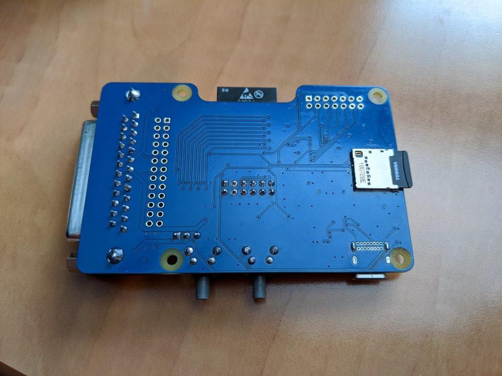
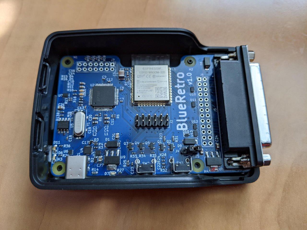
It took me all week but I'm finally done with the assembly of the prototype PCB. I had multiple issues mostly related to overestimating my own SMD soldering skills! The board look awesome and everything works very well.
I'll rework the PCB to use a few bigger parts since I got plenty of space and I will order another batch that will hopefully be the final one. I'll work on the DB25 level shifter board PCB next.
Here a list of the various issues:
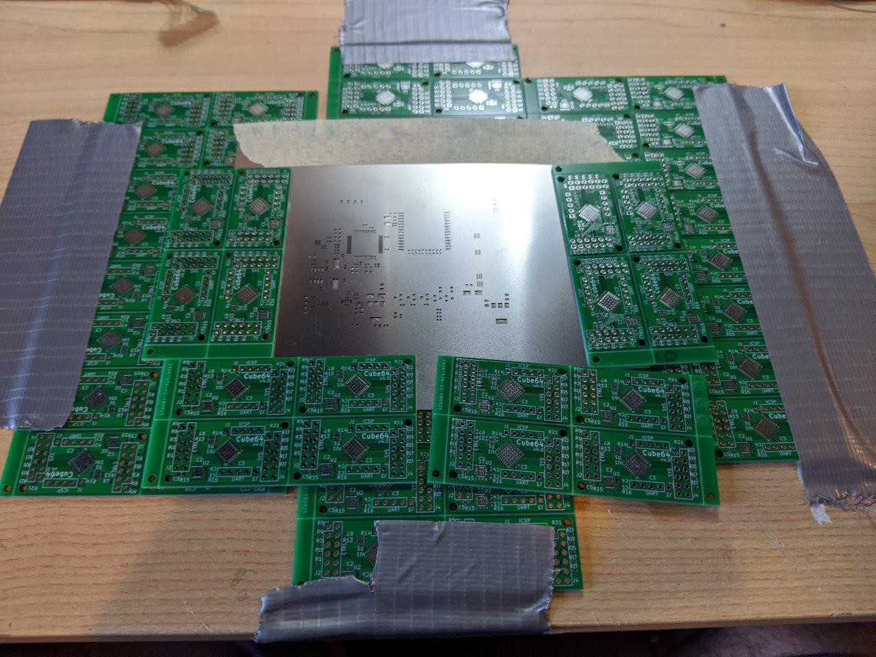
I had some trouble right away applying the paste using the stencil. Most of the paste for the FTDI chip got stuck in the stencil when I removed it. Using previous project panel to level stencilSo I had to put the paste manually which turnout out to create a lot of shorts. I end up removing the chip entirely and start again.
3/5 of the ESD chips used for GPIOs and SD card had 2 pins short, I had to remove those chip and install again a few times until it worked. I will replace those chip with bigger part for the next PCB version.
I had used the reverse version of the LDO previously which had the thermal pad connected to VOUT. I decided to use non-inverted version for BlueRetro and assumed it would be the same since the datasheet made no mention of what the Tab pin was. Turn out that I was wrong and on a SOT-223 package you need to know that the tab is always tied to pin 2. I simply had to cut two traces on the PCB to fix this.
I made the mistake of using a 0201 package for a diode. While 0201 is possible to do by hand for a cap or resistor, it's completely impossible to do for a diode since it needs to be in the right orientation on all 3 axes! I ordered a bigger one and hacked the PCB a bit.
I use jumpers to connect ESP32 TX/RX pins to the UART-USB bridge and I got it wrong, so I needed to use jump wires to cross it.
USB didn't get detected by PC, after troubleshooting I notice I had 0V on the 1V8 rail! I had a cold joint on the 1V8 output pin of the FTDI chip.
FT_Prog didn't detect the EEPROM and the TX/RX LEDs didn't work. Turnout I had another cold joint on one of the FTDI 3V3 pin.
Forgot to add header pins name on silkscreen.
Here a list of the various tests I made with the board:
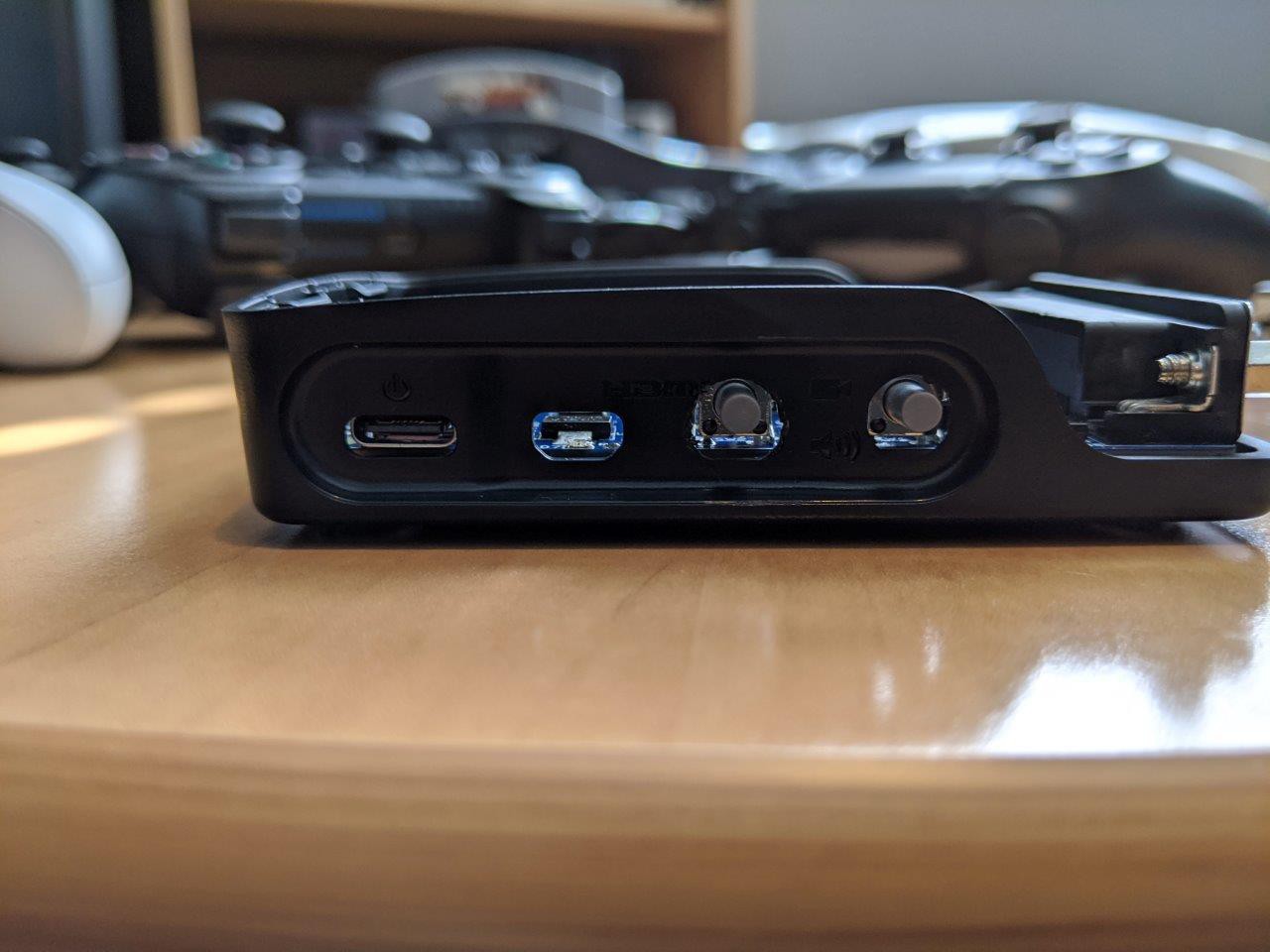
Reset & Boot switch work.
UART over USB A-C and C-C cables work.
Auto-program circuit work and ESP32 is successfully programed without touching any switch.
SD cards work and do not interfere with ESP32 programing.
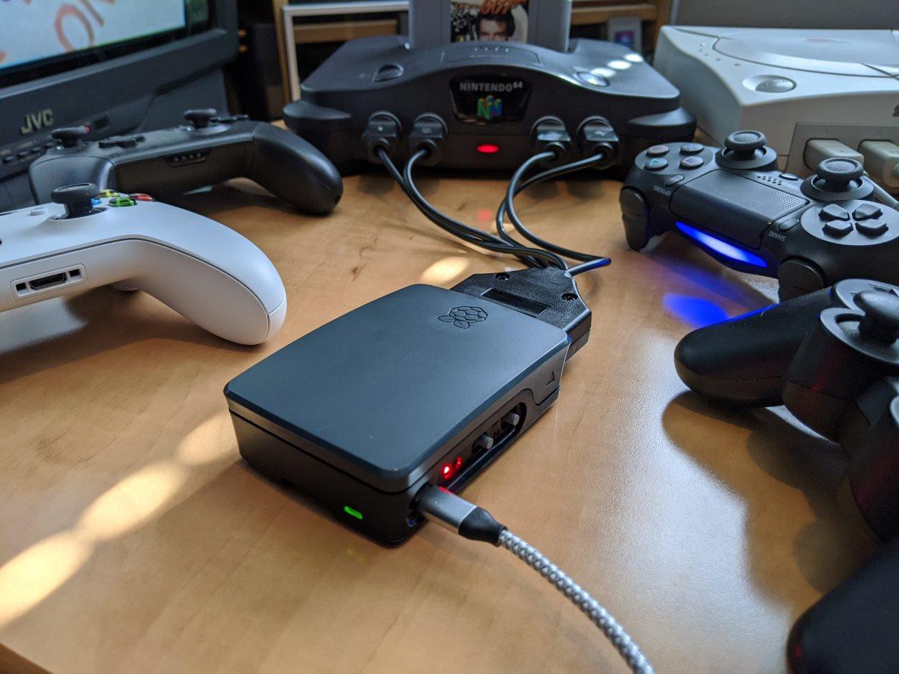
ESP32 can be powered by either USB VBUS or from console VIN (5V or 3V3) power.
Connected 7 Bluetooth controllers.
Tested 4 players with rewired N64, GC & Dreamcast cables.
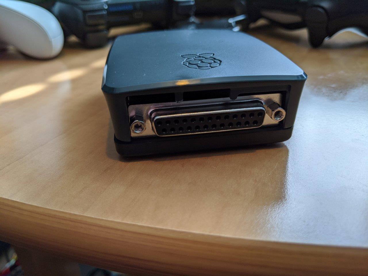
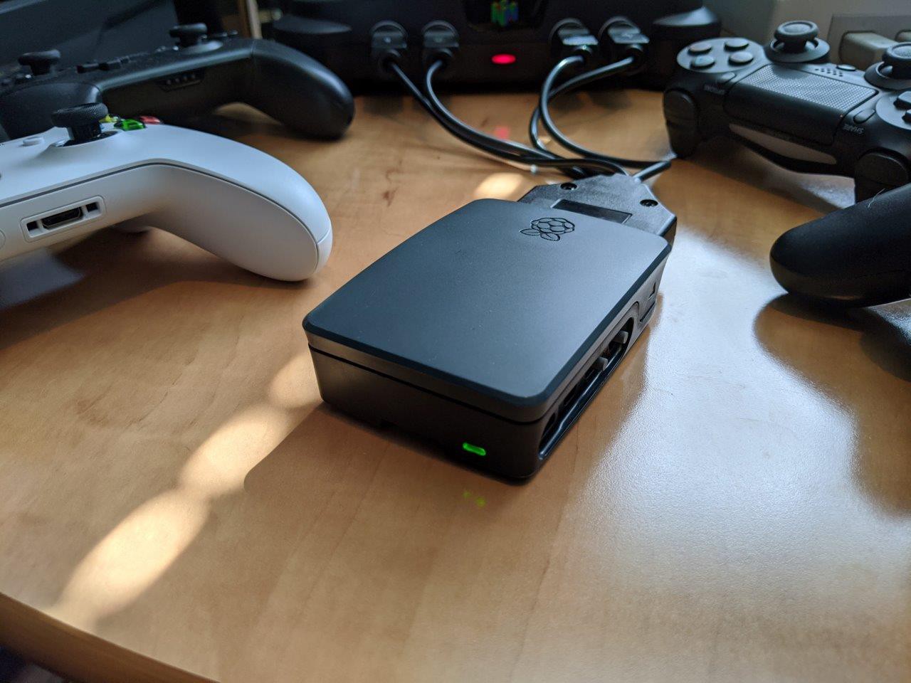
Mechanical fit with Raspberry Pi case is perfect! Only need to cut the cover two tabs and making one of the HDMI hole a bit bigger.
When ESP32 is powered from system VIN, tested I can see the boot log from UART when I power on the system.
 Jacques Gagnon

Discussions
Become a Hackaday.io Member
Create an account to leave a comment. Already have an account? Log In.