Finally finished the cable adapter PCBs design. While they are much simpler than the main BlueRetro board, I somehow made tons of errors while I was doing the schematics that I only figured after the routing was done! I somehow inverted the DB25 pinout. So I had to do each board twice! I think now they are fine after triple checking. I'll do another check before ordering the PCBs tomorrow!
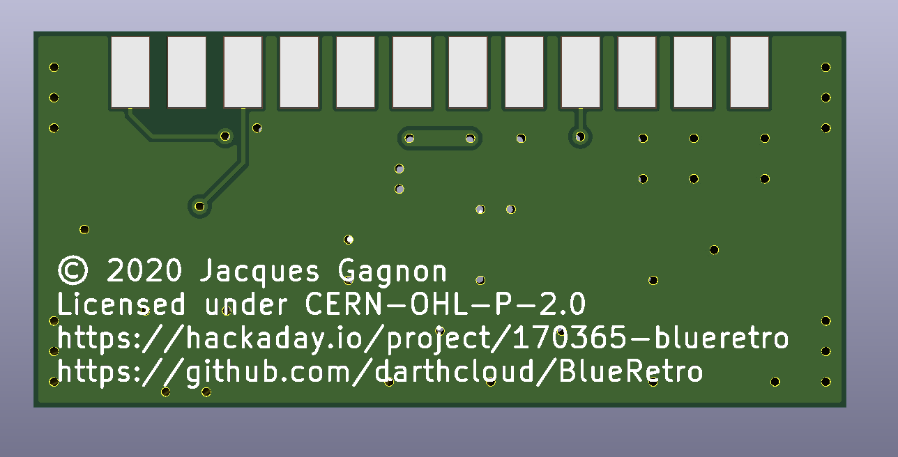
Passthrough adapter PCB
This PCB is used with every system that used 3.3V logic. It includes a jumper on I39 for selecting between two systems sharing the same detection pin. Several pad for power lanes are available to make it easier to solder wires for systems with 4 ports.
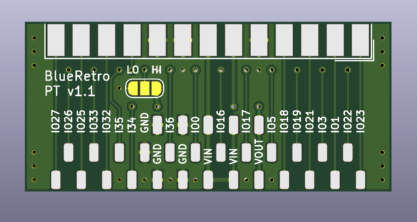
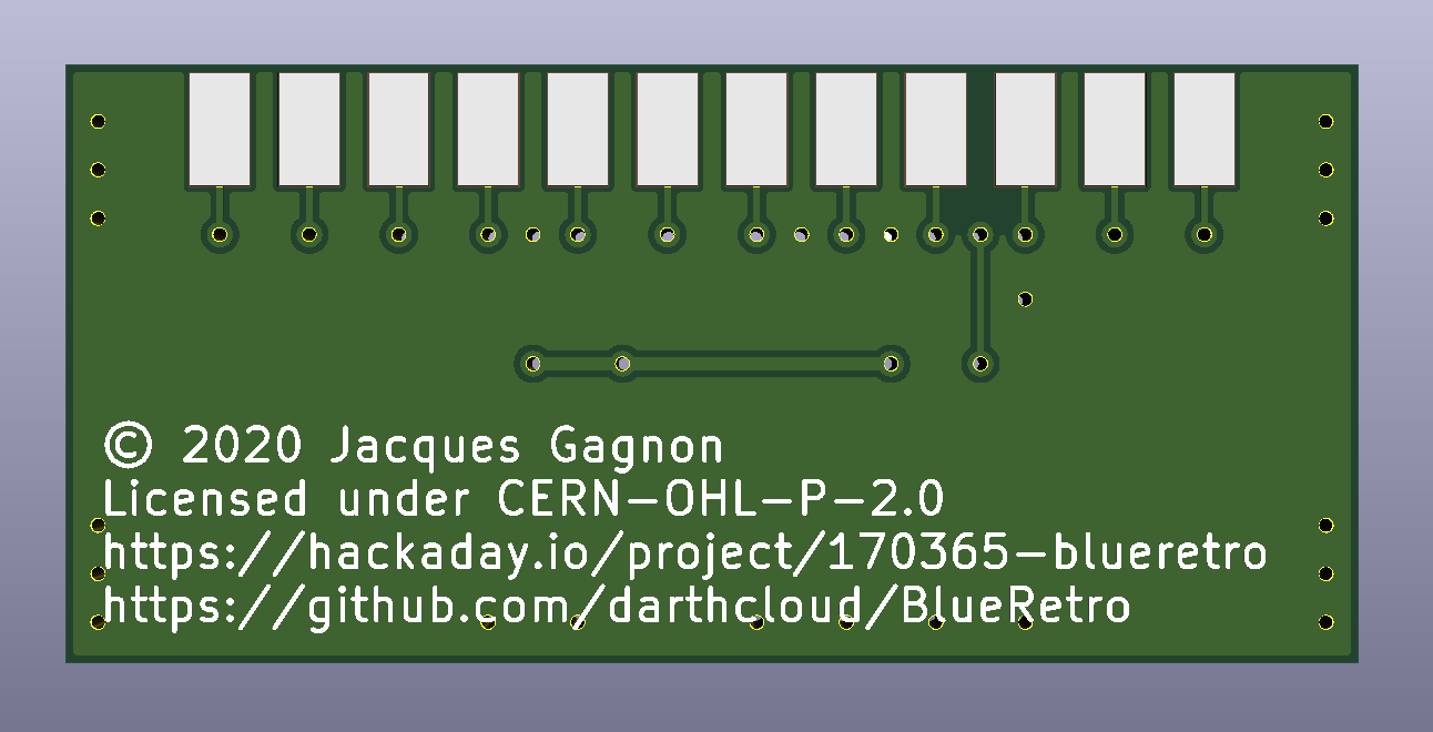
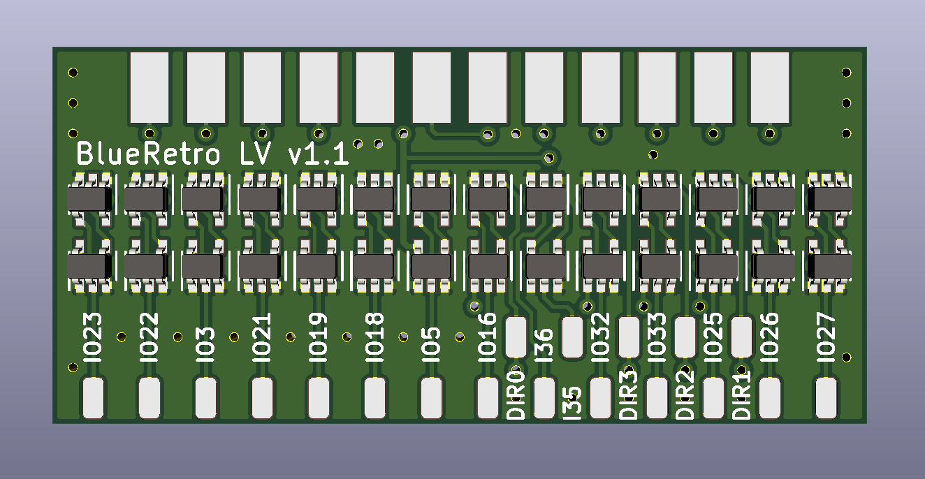
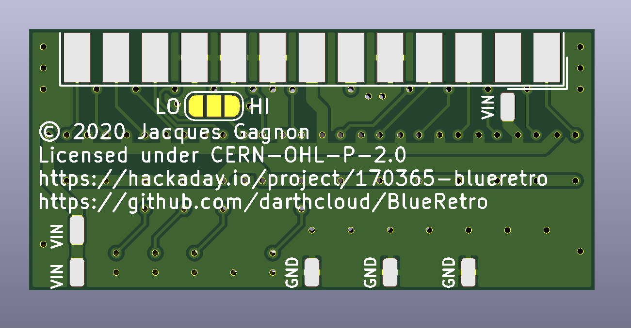
Level Shifter adapter PCB
This was the trickiest board to route. This board will be used for all systems that use 5V logic. I'm using single gate chip transceiver 74AHCT1G125/126 (Only difference is the OE input that is inverted or not). Most system will only need the 125 variant in either the top or lower row. Each system will only populate the required gates. While most systems have their signal in a fixed direction, the Genesis/Megadrive got a few bidirectional pins that change direction when using the gamepad or the multitap. In that case both the 125/126 will be loaded on those signal and the direction will be toggled via another pin via the DIR pads.
JVS adapter PCB
Japan arcade board use a serial interface base on RS-485, this board include the RS-485 PHY and one level shifter for the 5V sense signal. Since no power is provided via the serial connection, this configuration will require powering BlueRetro from USB power. However, only 3.3V is output from DB25 for protection. So a small 3.3V step-up circuit is included to provide the level shifter 5V supply.

 Jacques Gagnon
Discussions
Become a Hackaday.io Member
Create an account to leave a comment. Already have an account? Log In.