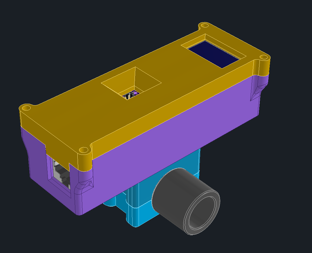
The design is 4 parts, 3D printed to enclose the electronics and mount the sensors
The parts are printed using Markforged White Nylon. Parts are tapped and screwed together with #4-40 hardware.
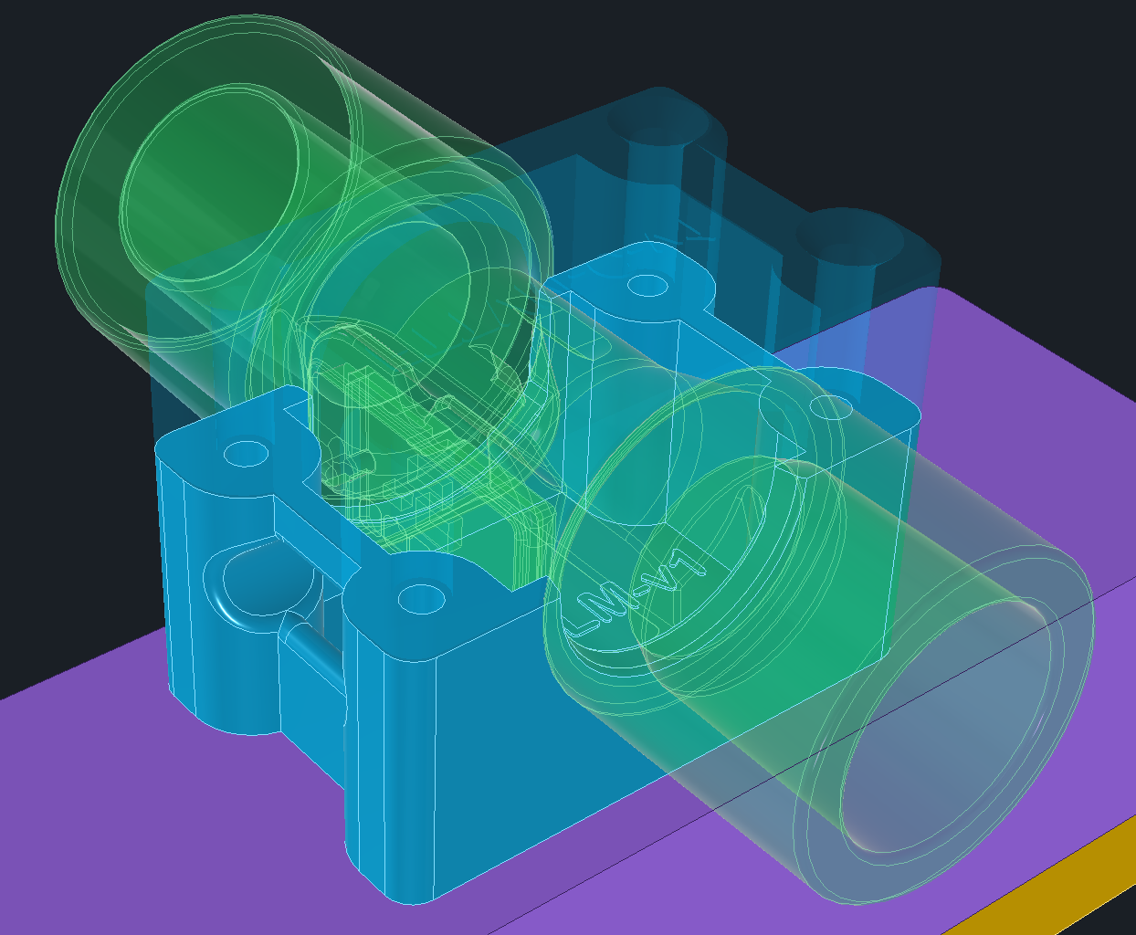
Sensirion provides a STEP file of the sensor so I created a split clamp design and subtracted the sensor from the clamp for a solid fit.
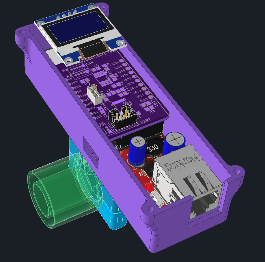
I had a test board for the Olimex ESP32-POE-ISO on hand, so used that to connect to OLED and UART with a MAX 3232 dual RS232 transceivers. The board has support for CANBUS, but that was for a separate project and not used here.
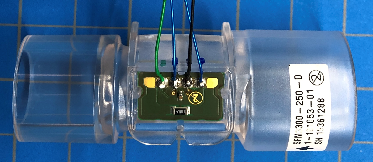
4 wires to the sensor, 5V, GND, SDA & SCL. I had limited colors so green is 5V, black is ground and the 2 x blue are i2c.
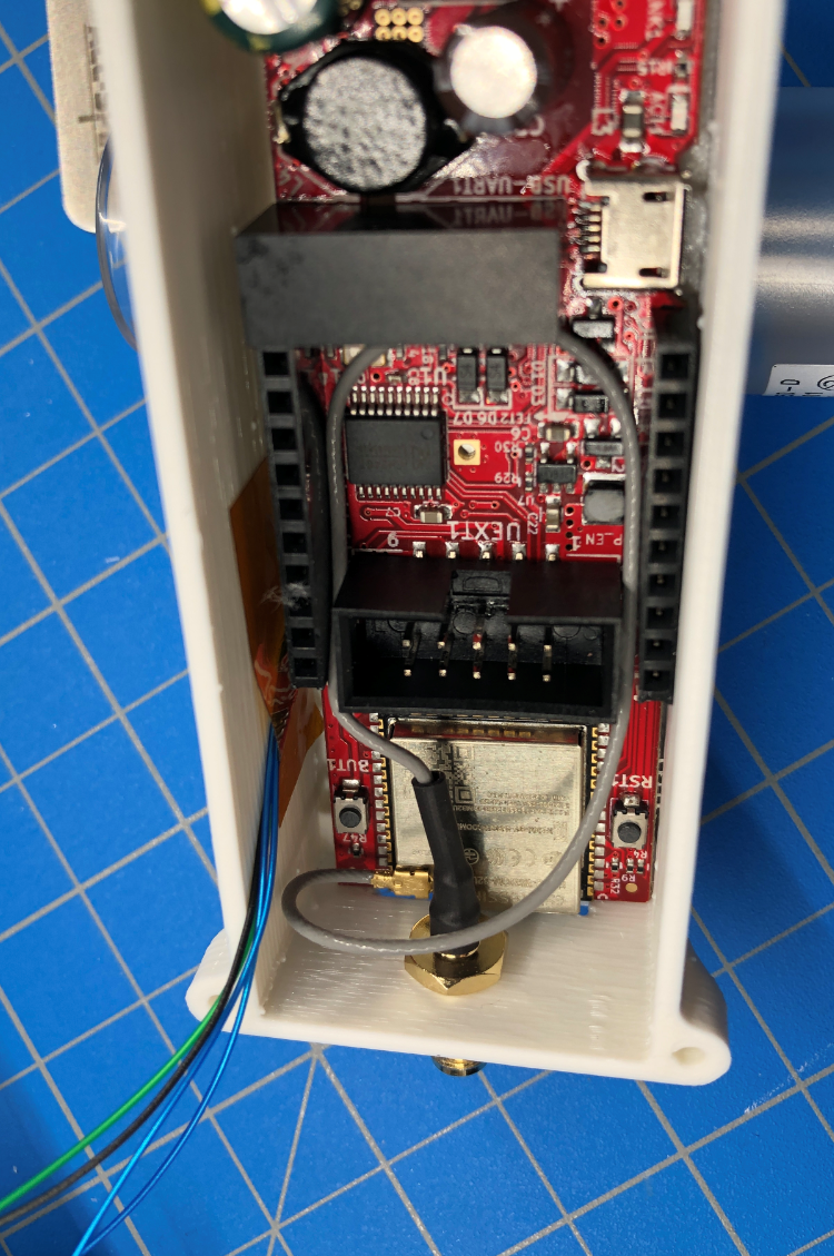
The wires come from under the Olimex. Taped to side of housing. I had a 2nd olimex with an external antenna, so had to pop in a hole for the antenna mount. Design works with on-board antenna normally. Routing the antenna wire is a bit tight.
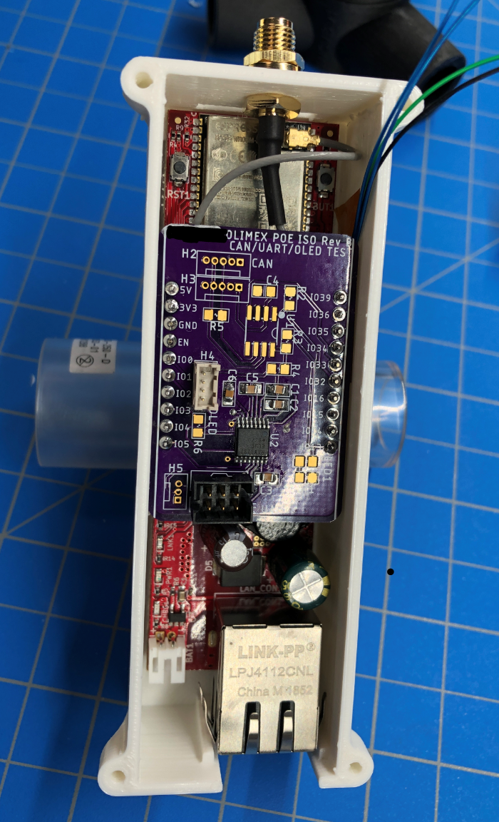
Here with the OshPark test board I had on hand.
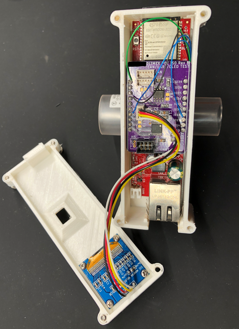
This is device #1, with the ESP32 with onboard antenna, which sticks thru a slot in the housing.
The sensor is wired directly to the pins on top of my test board.
- BLK - Gnd
- GRN - +5VDC
- BLUE # 1 - SDA GPIO2
- BLUE # 2 - SCL GPIO15
Eagle file for this board on Github.
 Patrick
Discussions
Become a Hackaday.io Member
Create an account to leave a comment. Already have an account? Log In.