 Sam Griffen
I have been using the time in lockdown as an opportunity to develop a wireless anemometer. The intention is to have an anemometer that can be mounted to a pole, charge an internal battery via small solar panel, and transmit wind data to a server. From here, I can develop a frontend that allows me to view the wind data from the intended turbine location.
Ideally, with enough data, I can determine the optimal location for my turbine. It will also just be cool to have realtime local wind data.
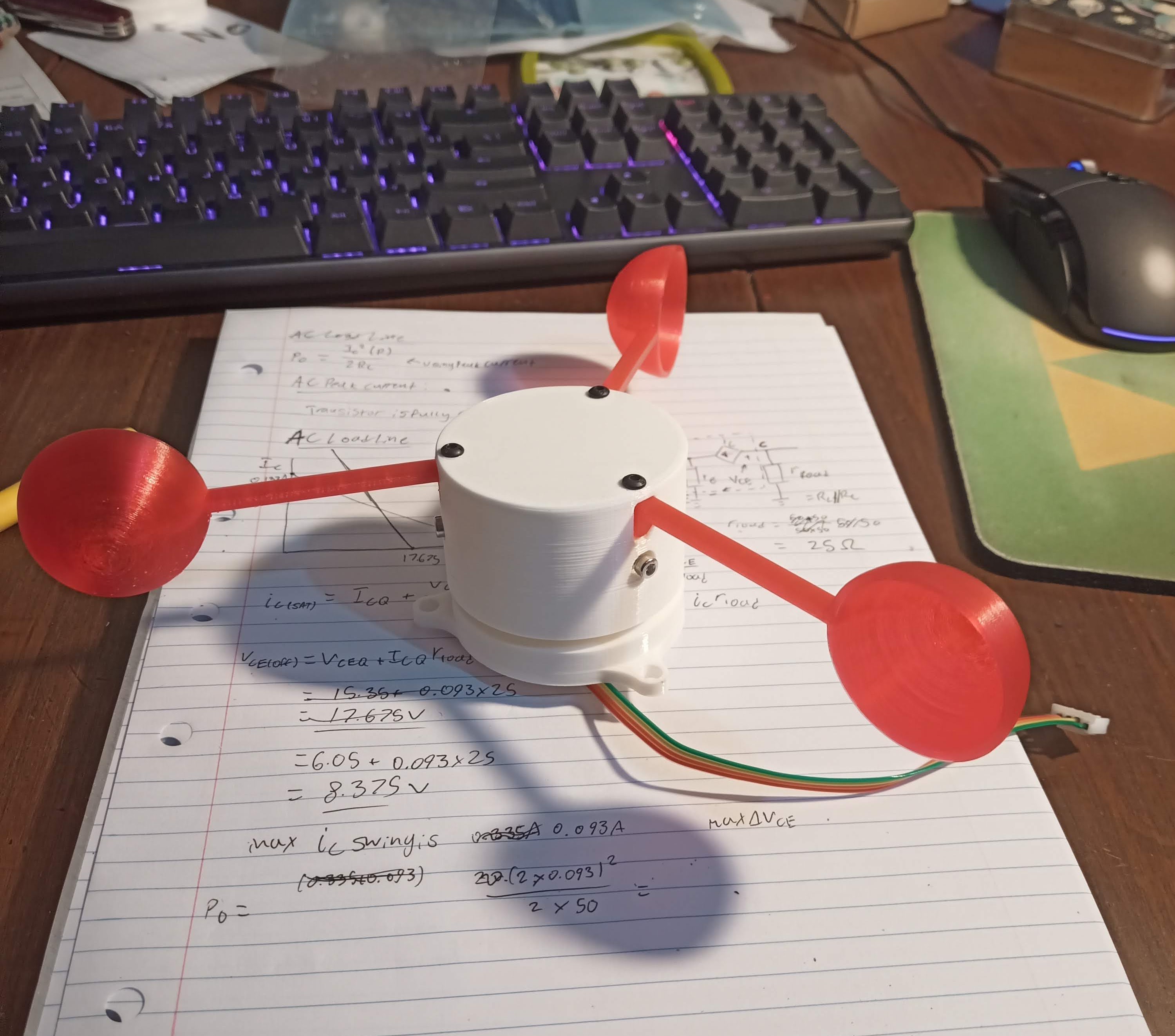
So far, I have created a headpiece for the anemometer. The top assembly clamps onto a bearing, which is in turn bolted to the bottom piece. This means the headpiece rotates freely about the base. The top piece has a small black section of plastic on the inside, exposed to an IR sensor mounted to the base piece. Using a TCRT5000 IR sensor, and an LM393 comparator, this sensor can be used to generate a pulse as the black section of plastic passes over the sensor. Ideally I would use a hall effect sensor and a magnet, but for the time being I need to work with the components I have. Below is an image of the headpiece as it currently stands.
Files for the anemometer can be found in this OnShape document. This is a working document, and will be modified as I progress.
There are a couple of issues to address with the current model:
- Bolts that clamp to the bearing should be shifted around the headpiece 60 degreses, so as to be out of the way of the cups.
- Cup mounting mechanism needs to be tighter, as some of the cups are not mounted securely.
From here, the next step is to develop the circuitry to detect rotation, connect it to the microcontroller, and use this to calculate windspeed. I'll check back in once I have this working.
Discussions
Become a Hackaday.io Member
Create an account to leave a comment. Already have an account? Log In.