 Adam Demuri
I assembled the initial boards (distribution board and fuse board small v1.1, fuse board large v1.0). Everything works fine. I made a few small tweaks after building this revision:
- Fixed silkscreen outline of the Anderson connectors. I originally followed the mechanical drawing, which appears to be incorrect (or at least misleading). I changed the outline to match the 3D models that Anderson provides, which seem to be more correct.
- Increased the copper ring around the slot slightly. I hope that this will make it easier to transfer heat to the copper on the PCB and make it easier to solder.
I haven't tested these changes yet, but they are pretty low-risk.
Load Testing
I applied a moderate load to boards for testing. I used a 100W, 2 ohm resistor with a 12V, "10A" power supply, and measured the voltage drop at the farthest connection point from the source. The power supply is cheap, so it drooped to 11.5v during testing, for a load of ~5.75A.
| Board | Voltage drop | Calculated resistance, ohms |
| Fuse board large | 0.03v | .0052 |
| Fuse board small | 0.04v | .0070 |
| Distribution board | 0.02v | .0035 |
These numbers are pretty approximate. They suggest that the resistance of the board is low enough to be negligible at reasonable loads.
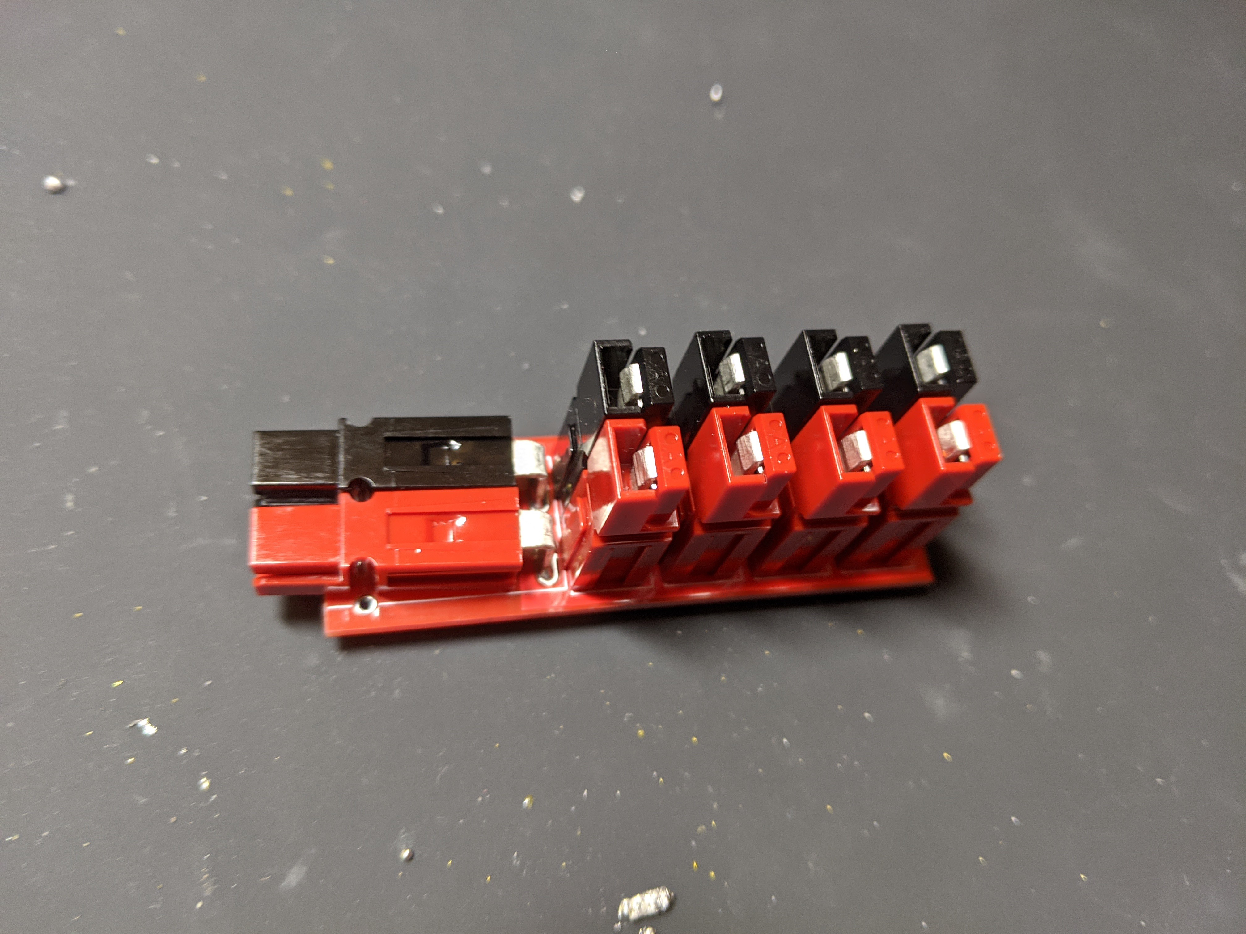
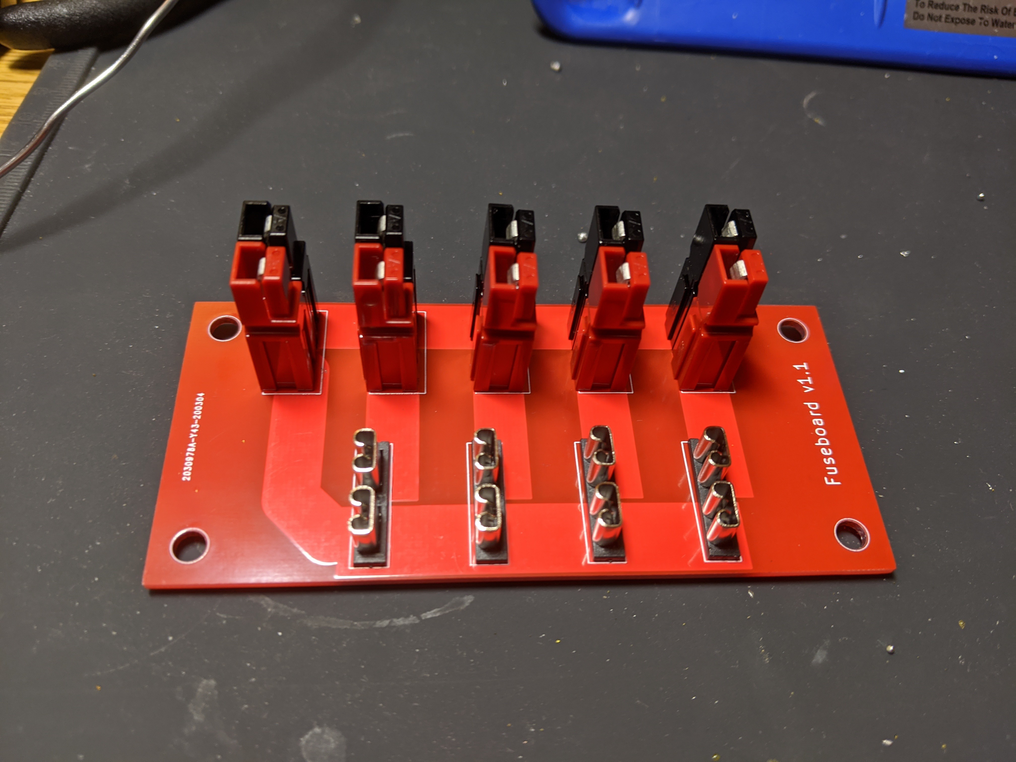
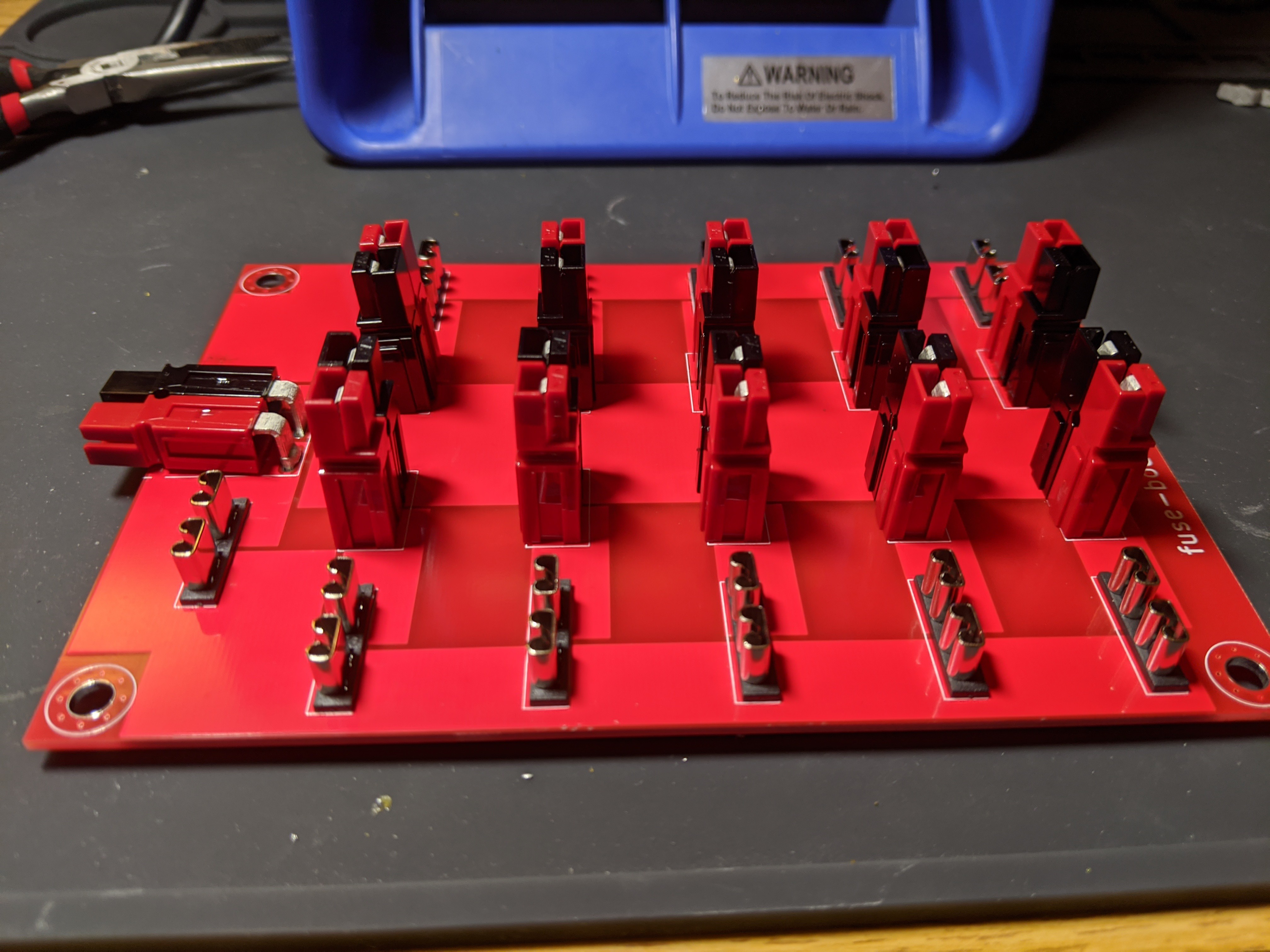
Here are the assembled boards:
Discussions
Become a Hackaday.io Member
Create an account to leave a comment. Already have an account? Log In.