0%
0%
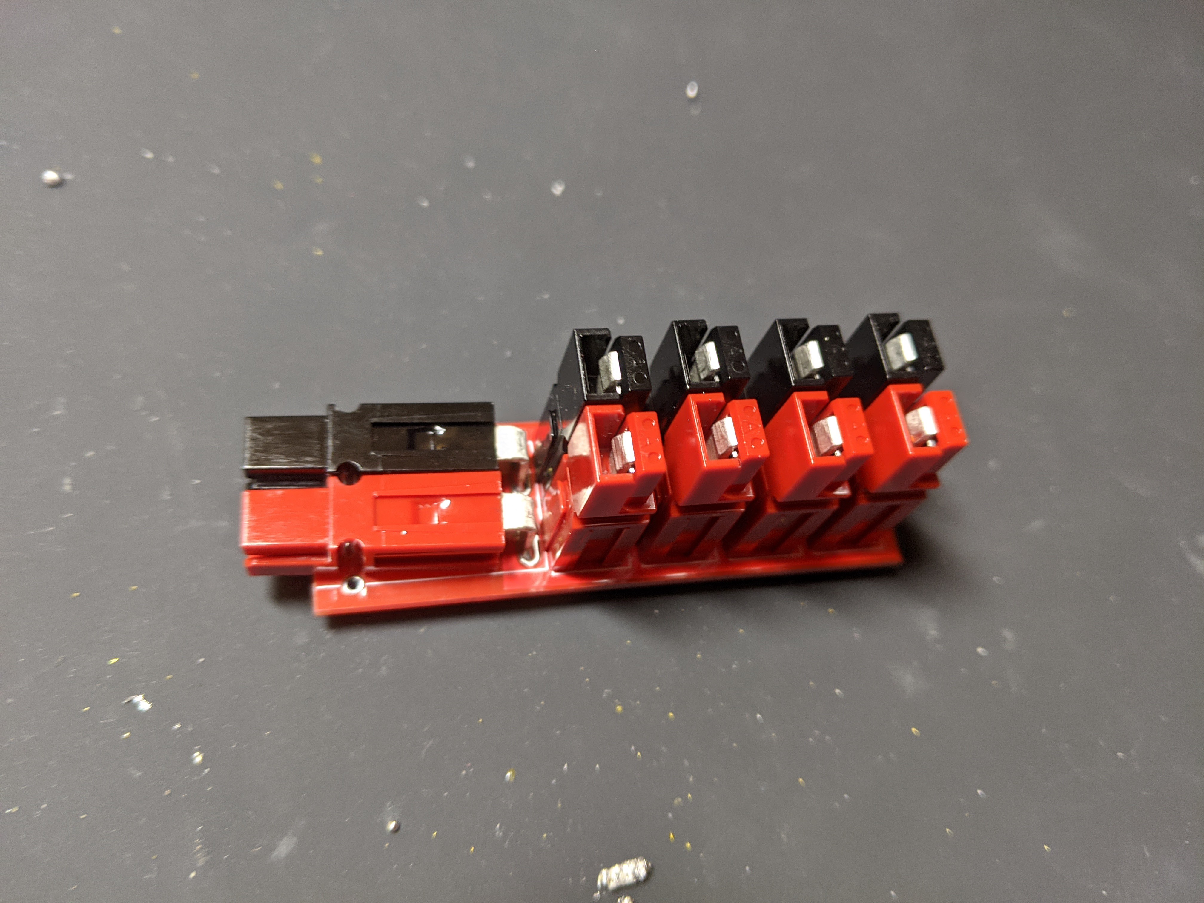
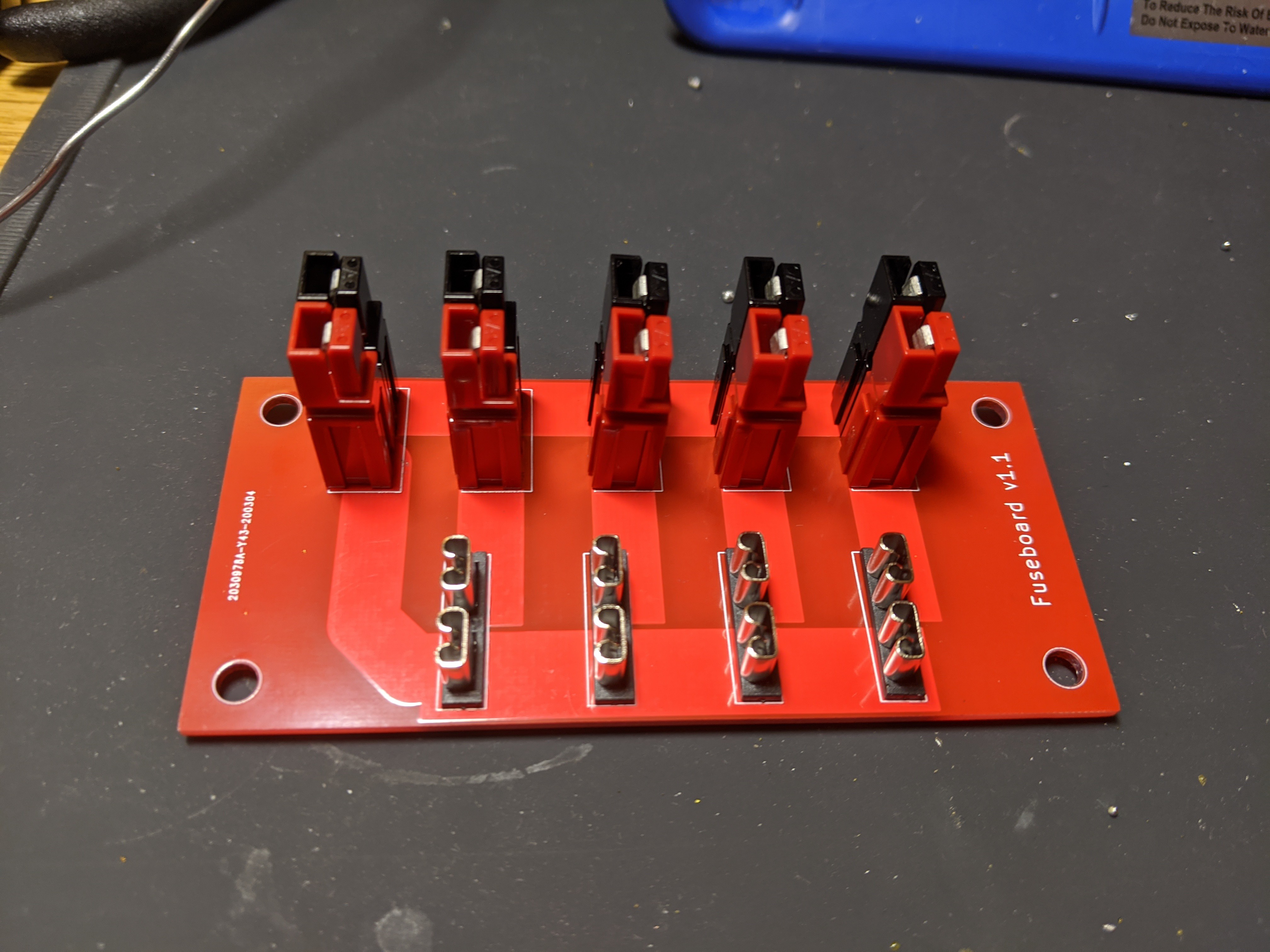
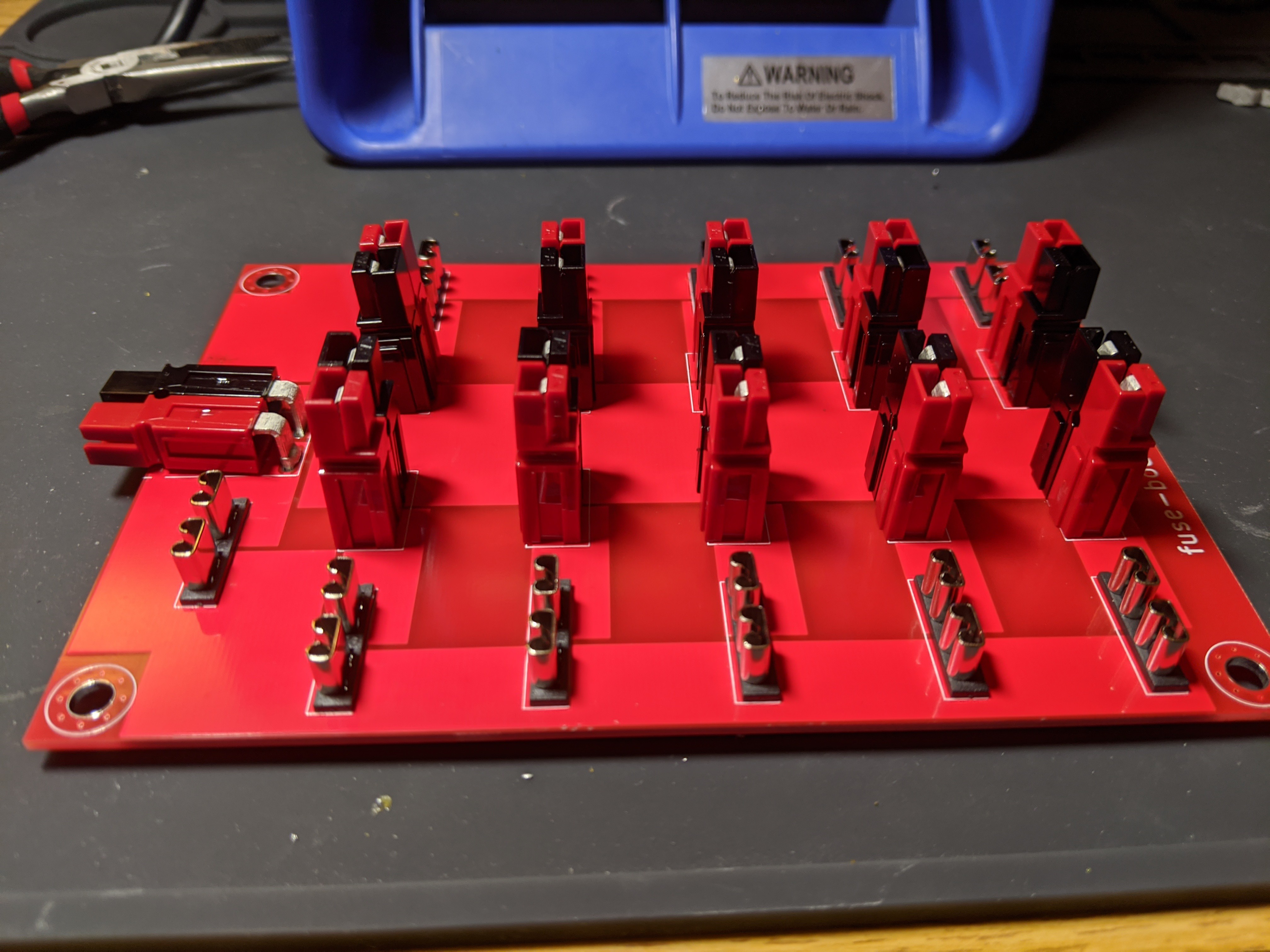
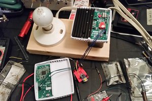
Anderson Power Distribution
Fuse and splitter boards that use Anderson PowerPole 45-amp connectors.
 Adam Demuri
Become a Hackaday.io member
Already have an account? Log in.
Just one more thing
To make the experience fit your profile, pick a username and tell us what interests you.
Pick an awesome username
hackaday.io/
Your profile's URL: hackaday.io/username. Max 25 alphanumeric characters.
Pick a few interests
Projects that share your interests
People that share your interests


 Jared Young
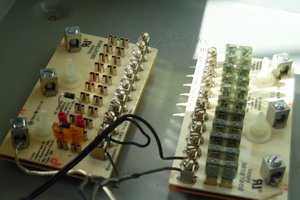
 cyplesma
 Daniel Garcia
I like what you did there: https://hackaday.io/project/163813-multilayer-recharging-18650-tower