Adam Demuri
-
Initial boards
03/21/2020 at 15:56 • 0 commentsI assembled the initial boards (distribution board and fuse board small v1.1, fuse board large v1.0). Everything works fine. I made a few small tweaks after building this revision:
- Fixed silkscreen outline of the Anderson connectors. I originally followed the mechanical drawing, which appears to be incorrect (or at least misleading). I changed the outline to match the 3D models that Anderson provides, which seem to be more correct.
- Increased the copper ring around the slot slightly. I hope that this will make it easier to transfer heat to the copper on the PCB and make it easier to solder.
I haven't tested these changes yet, but they are pretty low-risk.
Load Testing
I applied a moderate load to boards for testing. I used a 100W, 2 ohm resistor with a 12V, "10A" power supply, and measured the voltage drop at the farthest connection point from the source. The power supply is cheap, so it drooped to 11.5v during testing, for a load of ~5.75A.
Board Voltage drop Calculated resistance, ohms Fuse board large 0.03v .0052 Fuse board small 0.04v .0070 Distribution board 0.02v .0035 These numbers are pretty approximate. They suggest that the resistance of the board is low enough to be negligible at reasonable loads.
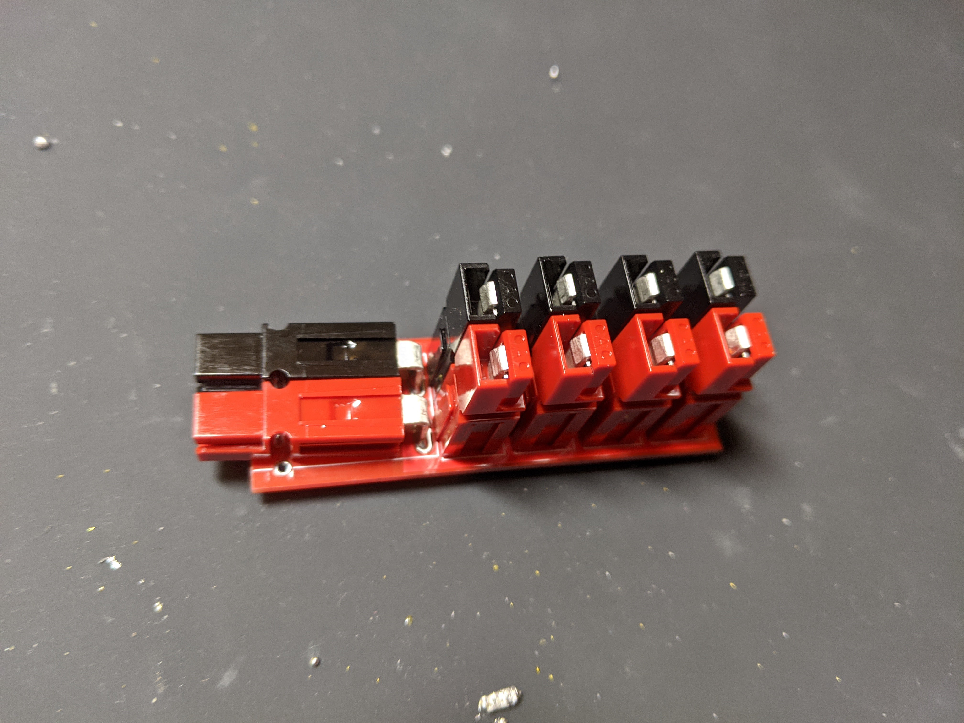
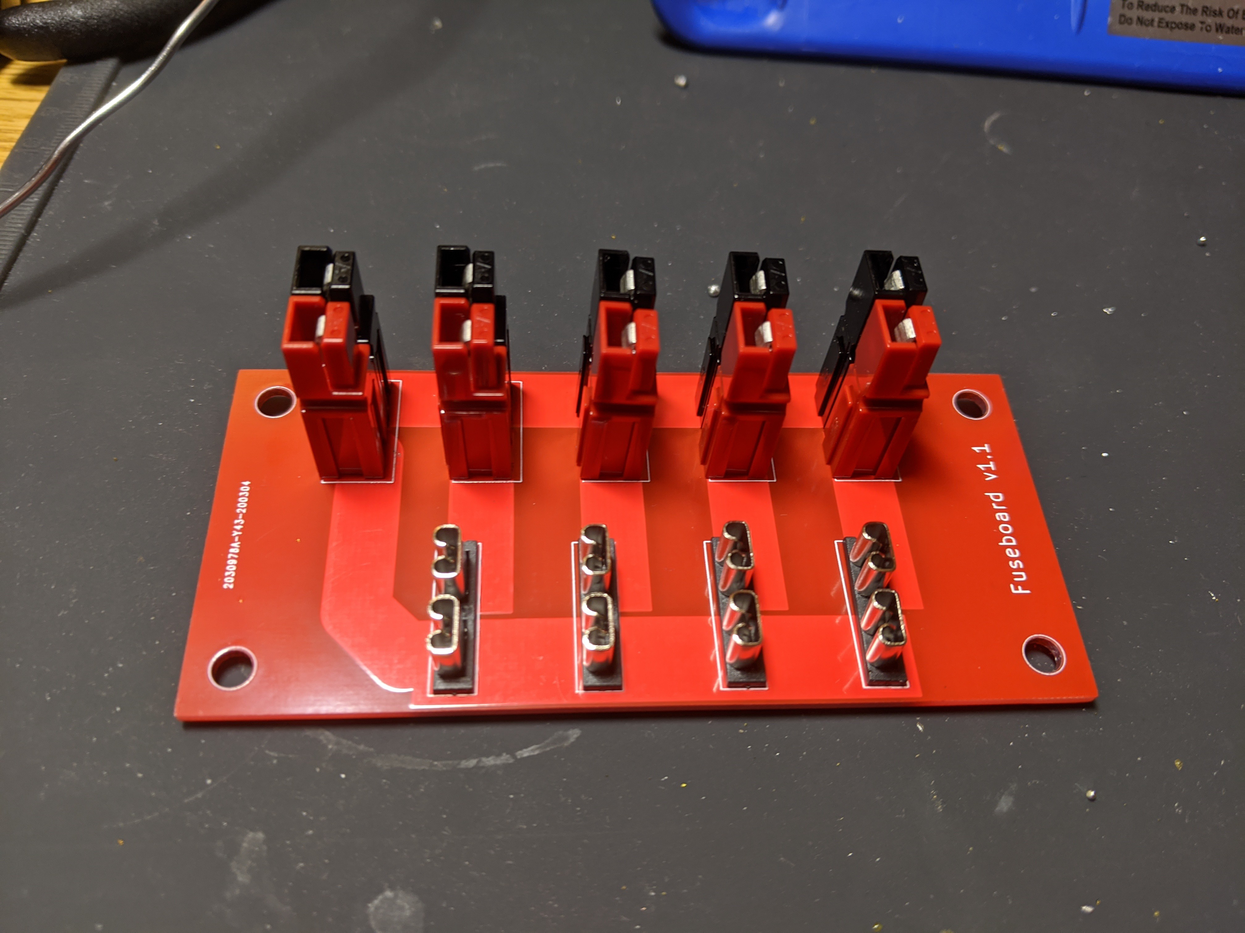
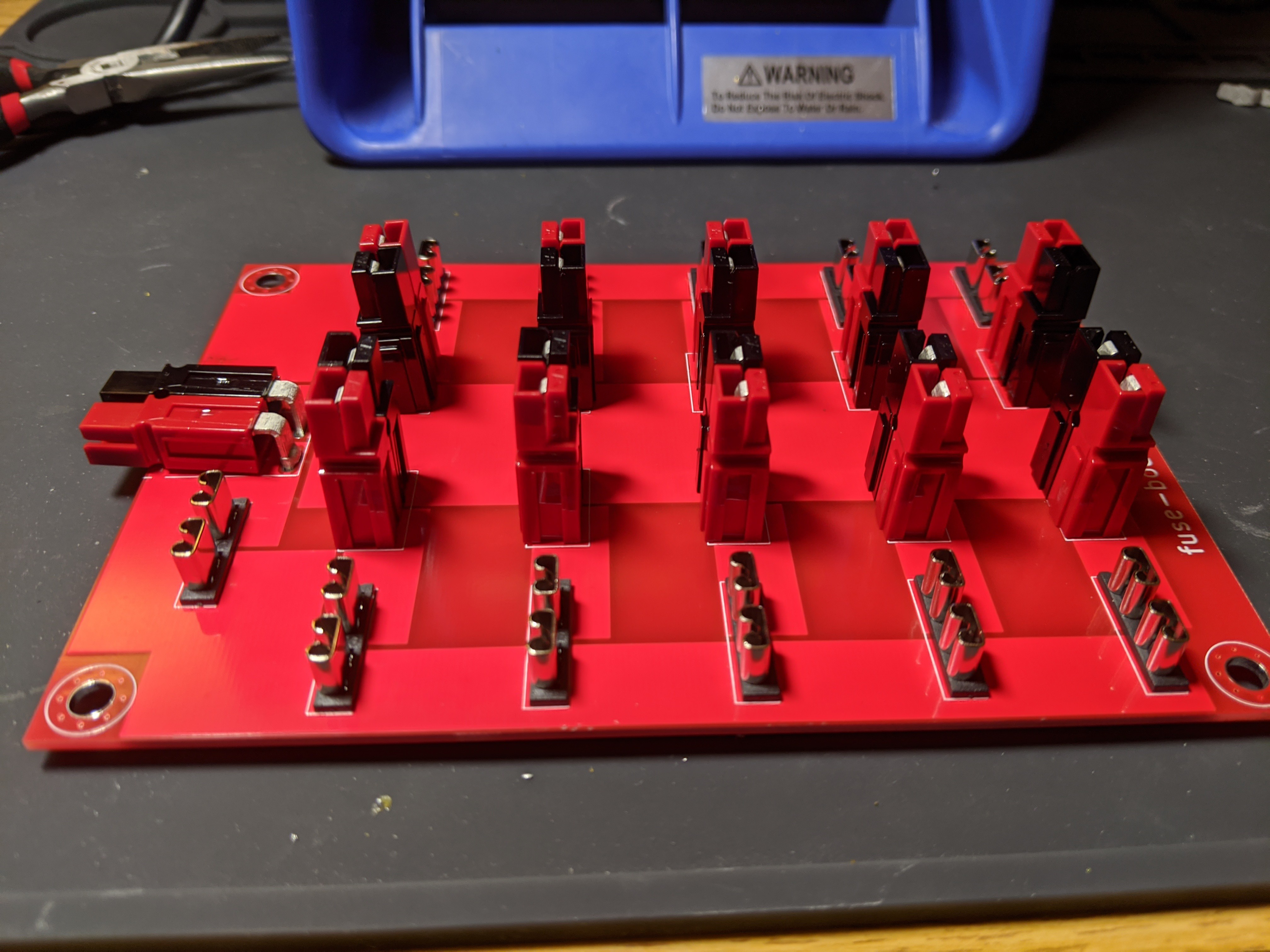
Here are the assembled boards:
![]()
![]()
![]()
Anderson Power Distribution
Fuse and splitter boards that use Anderson PowerPole 45-amp connectors.