Multilayer Recharging 18650 Tower
A scalable multilayer charging station for 18650, and possibly even other battery types.
A scalable multilayer charging station for 18650, and possibly even other battery types.
To make the experience fit your profile, pick a username and tell us what interests you.
We found and based on your interests.
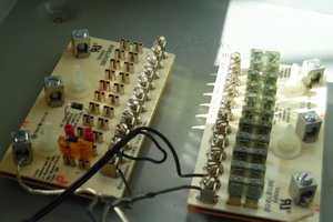
20221211_124747.jpgTray with JLCPCB manufactured tray power distribution board, along with my original prototype tray power distribution boardJPEG Image - 2.39 MB - 12/11/2022 at 17:52 |
|
|
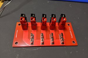
20221211_124757.jpgMain power distribution boardJPEG Image - 2.43 MB - 12/11/2022 at 17:51 |
|
|
20190422_224423.jpgComponent side of the charging tray power distribution board up closeJPEG Image - 173.58 kB - 04/23/2019 at 02:51 |
|
|
20190422_224411.jpgSolder side of the charging tray power distribution board up closeJPEG Image - 215.32 kB - 04/23/2019 at 02:51 |
|
|
20190422_224355.jpgCharging tray power distribution boardsJPEG Image - 227.06 kB - 04/23/2019 at 02:51 |
|
|
I spent spent quite a bit of time doing video and getting 2 boards to work on the charging tower. I have already started on 2 more. Sadly it's spring time and the honey do list for the outdoorzy stuff is growing in prior per the honey. I just need to get motivated now to finish it up with a total of 4 boards which I believe the cpu power supply should be able to handle.
Got my charging tray power distribution boards in. I got one soldered up and I will use that to do the cutout and endpoints to the board for the wires that need to be routed in the charging tray itself.
Spent a couple of hours a few days ago designing a new power distribution board to use on the charging tray. This way I can solder the wires to the through holes on the board instead of recreating the mangled mess like I did on the first charging tray. JCL has the boards and en-route as of this log entry.
OK/Alrighty got a single tray up and running
Just added some pictures to show how I prepped the power adapter board.
OK, making some real progress. I have my first charging tray all set with the exception of actually adding the cell holders that have their TP-4056s soldered to them. I also have the other trays cut from their stock so I can start milling, drilling and trimming that will be needed to get those set to wire up to my ATX adapter board.
I will also in about an hour from this post get a video summary of where I am at uploaded to you tube.
The ATX Adapter boards I designed up in EasyEda and ordered through JCL showed up in the mail and seems I got the ATX 24 Pin vertical pin dimensioned correctly on the board. I do have the Gerber file in the files for this project for just the ATX connector. I did get everything soldered up except the male terminal connectors since I am still waiting for those to show up. Just hoping I got those mounting dimensions correct.
There are pics of the everything soldered to the board (except the male terminals as mentioned) in the files.
Added a few more pictures, to show some progress, I am expecting my ATX power adapter soon. I'm just hoping I have the right dimensions for the PCB mountable spade terminals. After the several reworks and restarts I did today to get as far as I did I'll be needing more practice at that aspect of these projects as well.
As you will see in the photos my solder skills have seriously depreciated in the past 20 some years, but this project should get that skill back in shape.
What I did get done was to solder the wires that will go from the TP4056 boards to the power distribution board on the charging tray.
Just a video update of the progress: Charging Tower Update
So my attempt to mangle an old CPU power supply did not go well. not sure what I messed up or maybe the old power supply was bad to begin with. Any I spent the past week trying my hand at setting up (drawing up in both Express PCB and EasyEDA) an adapter board to simply connect the 20/24 pin CPU power supply cable to a board and setup some fused 5VDC connections. 5 volts is all I'll need for this project.
I started with Express PCB liked what I had and even setup another adapter board to be able to use the other voltages on the 20/24 pin connector as well.
The problem I ran into was finding on either Express PCB or EasyEDA was a ready made 20 pin PCB layout. The pins are not standard and during this time I come across someone else's adapter board for electronic bench power supply that is also fused and has a switch mounted on the board.
Really long story short the board I made in Express PCB which I was able to print I was able to see my layout for the power supply connector was no where near right. and I had a lot of difficulty getting to be right. I bought the power supply connectors from Spark fun and I had made the board before they showed up. Needless to say I now have 5 boards ordered through EasyEDA and I hoping I designed the power connector correctly cause as I stated neither of these programs had ready made versions. I have added a screen shot of each board from both programs to the gallery. EasyEDa was by far the better price just under 40.00 USD for 5 boards where ExpressPCB would have wanted around 150.00 USD for 3 boards. I did select 2 oz copper since it is for power and I expect a few amps to be flowing through this board.
I wasn't able to print in EasyEDA or at least I haven't figured it out how to yet. That would be nice to have/know to check the pin footprints on nonstandard pinouts. When I get the boards in a week or 2 and they are good I will share the gerber file for the EasyEDA version. I will wait to see how I did till then to create the power supply based on this same concept for my XYZ platform project that will need 5VDC and 12VDC.
Create an account to leave a comment. Already have an account? Log In.
Become a member to follow this project and never miss any updates

 Ian Hanschen
 cyplesma
 Adam Demuri
 Colin Catlin