Close
0%
0%

Adventures with a STC89C52 development board

Quick way to start with MCUs

Similar projects worth following
A STC89C52 development board that has a small set of peripherals onboard is a quick way to get started with the modern descendants of the Intel 8051 MCU family and MCU programming. As a bonus some AVR chips are also supported.

Motivation

I was searching for something do with the couple of AVR chips I have, as one of my wishlist items is to learn this family. At the same I was reading about the STC family of 8051 descendants and other cheap MCUs. I had thought I would not explore this MCU family any further after my tuner project using an original 8051. I had decided to make STM8 and STM32, far cleaner architectures, my go to MCUs, But I was tempted by the development boards available. Unlike breakout boards, these come with a number of peripherals so you can start making things blink and beep right away. Prices start from $10. With a platform like the Arduino you have to add shields or connect components on breadboard to interface with the outside world. So it will cost about the same.

My primary interest is not the programming as I know that I can beat any architecture into submission, or work out that the hardware is not up to the task. I'm more interested in putting together software toolchains for hardware, so that I can put the MCU to use later. None of what I do is groundbreaking, as others have already shown the way, but I can bring the information together in one place.

When it comes to deployment, you are able to buy the STC89 series in DIP-40 starting around $1. DIP-40 helps if you are learning to design your own PCBs as the larger dimensions of THT parts are more forgiving in the soldering skill department compared to SMT.

Board selection

If you search on Aliexpress or eBay with say "stc89c52 development board" you will get lots of hits. Be aware that boards vary in capability. For example

  • Pre-assembled or self-assembly, the latter is cheaper but if you want to get going right away and not worry about your soldering skills, then opt for the former
  • Power supply, some have barrel connectors, some use USB sockets which I prefer, but then you may be limited in current draw
  • Serial interface, some use RS232, but I prefer boards with USB to serial converters like the CH341 which means only one cable to your development computer is needed
  • Peripherals supplied, some provide you with a plug in 1602 LCD parallel interface module
  • Some cater for AVR chips like that ATMEGA 8515 by changing one jumper (the reset polarity is the reverse) as the port pins are the same. Of course the architecture is different so you need a different toolchain and download method.
  • Related to the former point, the board may have a connector for ISP for AVR MCUs; the STC MCUs are programmed using the serial interface

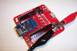
In the end I chose one with support for AVR chips thus fulfilling one of my original intentions. It's the one depicted in the photos, except that mine has black connectors. Rats, I was hoping for the more attractive yellow connectors. 🙁

Of course, the MCU is not soldered in but mounted in a ZIF socket so you can test other MCUs.

One detail about my board is that the crystal is plug in, not soldered. It comes with a 11.0592 MHz crystal, but you may wish to substitute others depending on the MCU you are experimenting with. But remember the frequency must also conform to any requirements for the serial interface which is used for downloading.

Software

I will mostly discuss Linux based software since this is what I use. But most of what I mention is also available on other OSes.

For the compiler there is SDCC which was originally written to support the 8051. The STC chips have a superset of the 8051 capabilities so you may need additional include files to define them.  The sample programs you can find on the Internet use the Keil compiler on Windows, and there is a free version of that with limited capabilities. You will need to edit those programs somewhat for SDCC. For those of you used to an IDE like Arduino, this may feel like a step backwards. But you'll find there are advantages to working at the command line level.

For downloading the programs to the board there is the stcgal program which is Python based so probably platform-independent....

Read more »

QX-mini51-schematic.png

Schematic

Portable Network Graphics (PNG) - 204.00 kB - 05/23/2020 at 02:32

Preview

qx-mini-diagram.jpg

Connector diagram

JPEG Image - 419.18 kB - 03/24/2020 at 07:15

Preview

  • An adaptor board for STC15F10x MCUs

    Ken Yap08/11/2021 at 12:19 0 comments

    Some months ago I came across an offer of 10 STC15F104W for about 30¢ each so I took the plunge. These are 1T 8051 MCUs with 4kB flash and 128B RAM. The only drawback is it is a DIP-8 or SOP-8 device so has only 6 I/O pins but this may be sufficient for small applications, and you can always extend the I/O with serial protocols.

    The datasheet was easily found with a search and In System Programming only requires Tx/Rx pins, readily available from a USB to TTL converter. But being a lazy person I wondered if I could use my QX-mini51 development board since it already has the converter on board and I have already set up stcgal.

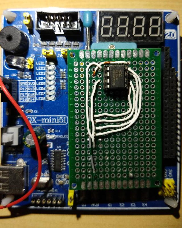
    Looking at the pinout, besides the power pins, the 6 I/O pins are port 3.0 through 3.5 with P3.0 and P3.1 used for serial communications. I just needed an adaptor. I had some prototyping boards of the right size, so I soldered a DIP-8 socket and then wires to 8 pins taken from a broken precision (round pin) IC socket. I'm feeling chuffed about not throwing that away. I don't really need P3.2 to P3.5 but I wired them anyway. I soldered another pin at 21 for better registration. Here's the result:

    BTW the datasheet suggests isolation diode and resistor to prevent powering the MCU from the USB serial adaptor. This is not necessary since there is only one power supply, that feeding the QX-mini51.

    I connected up the board to the USB port, ran stcgal, pressed the power switch and got this:

    $ stcgal 
    Waiting for MCU, please cycle power: done
    Protocol detected: stc15
    Target model:
      Name: STC15F104W
      Magic: F294
      Code flash: 4.0 KB
      EEPROM flash: 1.0 KB
    Target frequency: 0.000 MHz
    Target BSL version: 7.2.5Q
    Target wakeup frequency: 35.650 KHz
    Target options:
      reset_pin_enabled=False
      clock_source=internal
      clock_gain=high
      watchdog_por_enabled=False
      watchdog_stop_idle=True
      watchdog_prescale=64
      low_voltage_reset=False
      low_voltage_threshold=3
      eeprom_lvd_inhibit=False
      eeprom_erase_enabled=True
      bsl_pindetect_enabled=False
      por_reset_delay=long
      rstout_por_state=high
      uart2_passthrough=False
      uart2_pin_mode=normal
      cpu_core_voltage=unknown
    Disconnected!

    If you're wondering why the target frequency is 0, this MCU family has an onboard oscillator.

    Update after 2½ years

    I finally got around to writing firmware for a project using these tiny form factor MCUs which I will post about in due course. However when I tried to flash the firmware on the MCU, I ran into some glitches which I am pleased to say I solved.

    1. A silly error on my part. I couldn't connect with the QX board until I realised that because I had an Arduino Uno plugged in, the QX board was allocated /dev/ttyUSB1 instead of the /dev/ttyUSB0 I wrote in my Makefile.
    2. I got my workstation talking to the MCU, but got this error message.
      Protocol error: uncalibrated, please provide a trim value

      A search took me to this issue in the stcgal project: https://github.com/grigorig/stcgal/issues/96 Simply put I have to provide an operating frequency for the MCU. This also answered my question about what frequency the timers would run at, which is important for timing in the firmware. I chose a trim frequency of 11059 (kHz) as it will match that of the STC89C52 normally on the QX. Although the STC15W goes to 35 MHz, speed is not important.

    3. Next I encountered this error message:

      Protocol error: incorrect frame start

      This took me to this issue: https://github.com/grigorig/stcgal/issues/17 It's quite a long thread but to cut to the chase, I needed to update my stcgal version, which simply required:

      git pull
      ./setup.py build
      sudo ./setup.py install

      It still wouldn't program at the default 115200 baud, but when I dropped to 38400 baud, it worked fine.

  • Crystal contacts

    Ken Yap09/16/2020 at 00:01 0 comments

    Just to mention that while the plugin crystal allows for a different one to be swapped in, contact can be sometimes erratic, causing the program to halt. Wiggling the crystal a little gets the program to restart. Fortunately I'm only using the dev board to prototype a circuit and will later have a PCB with a soldered-in crystal for a project.

  • Clock firmware project added

    Ken Yap08/22/2020 at 07:26 0 comments

    I have added a clock firmware project prototyped using this dev board and a DS3231 RTC board to Github. Details are sparse because I intend to build a board for it, make it a project in its own right, and take it futther in due course, but it should be possible to work out what goes where from the program.

  • Tested with new old batch of MCUs

    Ken Yap07/04/2020 at 09:14 0 comments

    10 STC89C52s that I bought for under a dollar each have finally arrived after braving the stormy seas, well empty skies, of this COVID-19 era. I put them on the dev board and tested with the usual blinky program. They didn't require the newer 7.2C download protocol in stcgal like the one that came with the board, so they were old stock. I'll be using the dev board to check my firmware for future projects, and I'll mark this project completed.

  • Sample programs for SDCC released

    Ken Yap05/14/2020 at 00:55 0 comments

    I have published the QX-mini51 sample programs, converted to compile with SDCC instead of Keil, at a new Github repo, see the list of repos referenced by this project. They are fairly basic but demonstrate how to handle peripherals on the MCS51 architecture. I have also included some code::blocks project files if you want to use an IDE to develop. I'd be interested to hear from people using that. I only read about it and installed it recently.

    Have a lot of fun.

  • Ran sample programs through translator

    Ken Yap05/08/2020 at 01:33 0 comments

    The comments in the programs for the Keil compiler are in Chinese so I ran them through a translator and then added them to the Github repo as parallel files. The translator inserted spaces in some places so they will provoke syntax errors if you try to compile them, so don't do that. They are only for reading the comments. Some are relevant such as notes that a jumper must be disconnected for a particular experiment. For example the port driving the LEDs is also used for input in some experiments so the LEDs need to be disconnected for those. Some comments explain the calculations behind time-critical delays.

    I will transfer the relevant comments to the SDCC versions which I'll be testing soon.

    I also found a higher resolution version of the schematic which should be easier to read.

  • Notes on converting Keil 8051 C to SDCC C

    Ken Yap05/06/2020 at 23:56 7 comments

    After having converted 30 odd sample programs from Keil C to SDCC, here is a summary of the differences I encountered.

    • Keil uses sbit to declare special bit registers using for example P0^7 to refer to port 0 bit 7. SDCC uses __sbit and a different syntax. But since most of the special registers are defined in SDCC includes, usually it suffices define your symbol to be the same as say P0_7.
    • Putting large constants, e.g. tables, in the RO code area in Keil is done with the qualifier code after the type declaration, e.g. uchar code table{] = …. In SDCC it's declared thus: __code uchar table[] = ….
    • Keil uses for example: interrupt 1 using 1 to qualify an interrupt service routine (ISR) as hooking to interrupt vector 1 and using register bank 1. SDCC uses the syntax: __interrupt(1) __using(1). Note that Keil makes interrupt and using unavailable for symbols. Ditto for sbit and code. Oh and remember that in SDCC the ISRs (or at least a prototype) must appear in the file containing main() or the vectors won't get initialised. This wasn't an issue for the sample programs as each was in a single C file.
    • Keil has a data type called bit, usually used for booleans. I didn't see any advantage so I converted those to char (which is actually uchar for the 8051 architecture).
    • The standard include in Keil C appears to be reg52.h. In SDCC it's 8051.h. Keil has additional includes like intrins.h and math.h, but these are not needed for SDCC. stdlib.h should be included if you use abs() with SDCC. stdio.h should be included if you use printf and the ilk for the serial port, and in the case of SDCC you need to implement int putchar(int) whereas it's supplied in the Keil library. If you have a MCU with more special registers then you should include the definitions for those. You may need to create your own if somebody hasn't done it already.
    • Keil appears to define a special function called _nop_(). For SDCC just #define that to __asm__("nop").
    • Not really a compiler difference but since Keil runs on a case insensitive OS, you can get away with #include <reg52.H> but you must respect the filename case on Linux.
    • Again not a compiler difference but the sample programs often used defines like #define uchar unsigned char. I prefer to use typedefs.
    • Keil lets you get away with a mix of old style and new style function headers, like int fun(int a,b), whereas you should use the standard int fun(int a, int b) in SDCC.
    • In one initialisation of a structure, Keil let the programmer get away with not properly nesting braces for a struct element. It was something like this:
    struct fontentry {
        uchar[3];
        uchar[16];
    } f = { "AB", 0x00, 0x01, … };

     The initialisers for the second uchar array needs to be surrounded by braces according to the standard.

    If I remember any other differences I'll edit this log.

  • Converted the charset of the sample programs

    Ken Yap05/06/2020 at 13:45 0 comments

    The sample programs in the repository that have been published on Github have comments in Chinese. However the encoding was GBK which was why they weren't displayed as Chinese characters but as octal codes or weird characters. Using iconv, I've converted those to UTF-8. So even if you can't read them, at least you can put them through a translator.

    Actually I discovered this after I had finished creating a parallel Github repository for compilation with SDCC instead of Keil as in the originals. So after testing the programs, I will translate some key comments and reinsert those into the programs. Stay tuned.

View all 8 project logs

Enjoy this project?

Share

Discussions

Similar Projects

Does this project spark your interest?

Become a member to follow this project and never miss any updates