-
1Step 1
Circuit Diagram
![]()
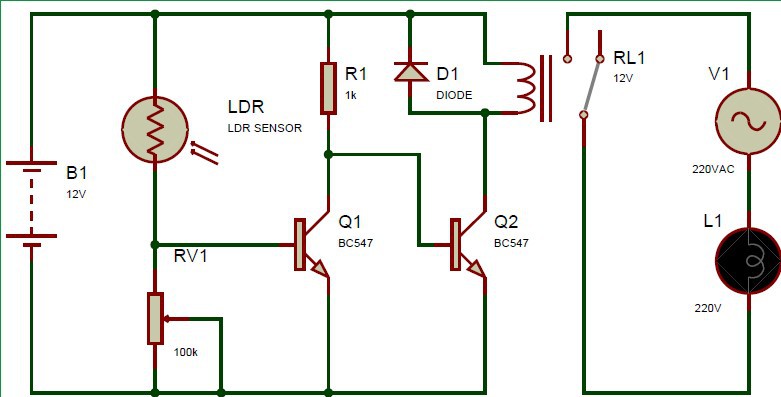
In this circuit, the LDR (Light Dependent Resistor) is used. The resistance of LDR varies according to the light and darkness and with the help of this resistance, it detects whether it is a day or night. Its resistance increases at night and decreases at day. At the end of the circuit, a simple AC load (Bulb) is used and it is operated with the help of relay. To operate the relay, the two NPN transistors BC547 are used.
Operation
When the light falls on the LDR, the resistance of the LDR decreases and the transistor Q1 turns ON. But the collector is at a low state and the input signal to the second transistor Q2 is not enough to turn it ON. Hence, the relay remains OFF.
When there is darkness, LDR resistance increases, the signal becomes low at the base of Q1. The second transistor Q1 gets a high signal and turns ON the relay. The AC load is connected to a relay circuit hence the bulb turns ON as well.
Automatic Street Light Controller
In today's age, the usage of energy matters the most. The steps are needed to avoid the misuse of energy and this project focuses on it.

Discussions
Become a Hackaday.io Member
Create an account to leave a comment. Already have an account? Log In.