 Pascal
With the mainboard taken care of, and a proper bus pinout defined, I decided to tackle the memory as next target. Compared to the original, I don't plan to use the old-style Intel 2112 RAM chips, but instead went for the cheapest non-volatile storage I could find on DigiKey:
The SST39SF010A
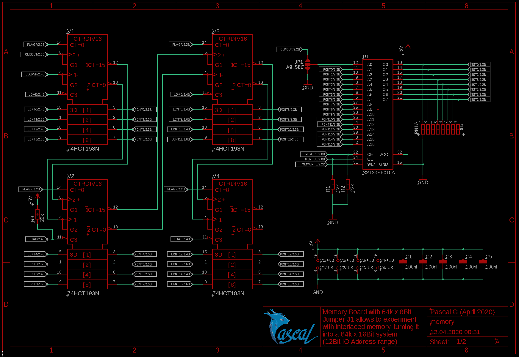
With it's 128k Bytes of flash memory, it's a beast compared to the original 256 Bytes of RAM. Not sure what I will do with so much RAM, but since it's also one of the cheapest solutions with 1.13CHF, I decided to stick with it.
To handle the 17 Address Lines, I use four 4-Bit Counters (74HCT193) which leaves only one address pin left - A0.
A0 is hooked to a jumper, which by default is connected to ground, so the Computer behaves just like the original WDR one. Alternatively and with bit of solder and a knife, it can be connected to the clock signal instead. This allows to turn it inot a interlaced memory board, which brings a 12bit wide IO structure, compared to the default 4bit one. More about it can be found in Motorola's handbook about the MC14500.
A layout goal for the Computer Cards, are to stay within 100 x 100 mm of size. Here's the resulting layout:
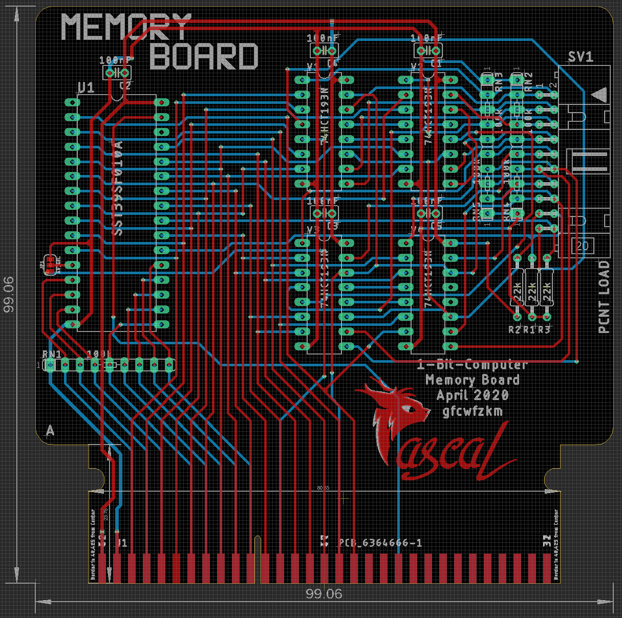
The connector on the right is hooked right up to the Address Counters, allowing to load a new address and to make it easier to implement a future, possible "jump & return" function.
Discussions
Become a Hackaday.io Member
Create an account to leave a comment. Already have an account? Log In.