Samuel A. Falvo II
-
Can a VDC-II Support a 8K Display?
04/27/2020 at 01:54 • 2 commentsI got an interesting (if not to be taken seriously) question on my Mastodon feed today: 8K VDC-II when?
For now, let's focus exclusively on the CRTC capabilities, and completely ignore the logistics of getting pixels onto the screen. The latter implementation details will necessarily have to change regardless, so I take it as a given that the VDC-II as I'm currently envisioning it cannot support anything greater than a 1K display.
So, let's look at what the current VDC-II's CRTC registers can do, in regards to 8K, 4K, 2K, and 1K displays, respectively. (By comparison, a 640x480 VGA display is 0.8K.)
The Original Question: 8K VDC-II When?
I'm pretty sure the CRTC interface of the VDC-II will need to be changed to support an 8K display. An 8K display resolution seems to be 7680x4320, at least that's what Wikipedia tells me. The VDC-II CRTC supports a maximum character cell width of 16 pixels; 7680/16=480, which is too wide for the 8-bit horizontal displayed register to hold on its own. Thus, the VDC will need either adjunct registers or an all-new 16-bit interface to cope with the additional bits needed for horizontal timing.
So, at present, the VDC-II is not able to handle 8K displays. Sorry. It probably can be made to support these large resolutions with relative ease; but, it'll require more investment in the hardware description, an FPGA fast enough to cope with the insane dot clock speeds, and testing with compatible display hardware.
What about 4K Displays?
It's so close! While the vertical resolution is achievable with relative ease, the horizontal direction proves to fall just short of the minimum required functionality.
A typical resolution for a 4K display with consumer hardware is 3840x2160, so I'll use that for my calculations. 3840 can be divided into 256 characters at 15 pixels each. The VDC-II, as I've currently defined it, does not support 256 characters; it only supports 255. However, a revision can be made to the hardware description where plugging a 0 into the horizontal displayed register (R1) could be interpreted as meaning 256 characters. It would require redesigning the display-enable circuit to be a bit more clever than "assert display enable as long as the display counter is non-zero."
The bigger problem is the horizontal total register (R0), which is used for HSYNC timing pulse generation. This requires more than 256 characters; if you think about it, the 256 characters discussed above are those which are the visible part of the display. So, unfortunately on this basis alone, the VDC-II cannot support a 4K display.
Things are a bit better in the vertical dimension, however. At 2160 pixels, we can reasonably fit 216 10-pixel tall characters on the screen, 135 16-pixel tall characters, or 108 20-pixel tall characters. All of these configurations are well within the realm of possibility for the current VDC-II design.
What about 2K, then?
2K video is a different matter. According to Wikipedia, the largest recognized 2K resolution is 2048x1080. From the point of view of the VDC-II's current CRTC implementation, this resolution is a cake walk.
With 16-pixel wide characters, the horizontal displayed register would be set to 128, which (if you follow the rule of thumb that active video takes 75% of the horizontal display time) means the horizontal total register would probably be somewhere in the vicinity of 170. These are all easily within the range of the 8-bit character counters as currently found on the VDC-II.
Similarly, in the vertical dimension, we're looking at a vertical displayed setting of 135 (for an 8px tall font), 90 (for a 12px tall font), or 67 (for a 16px tall font). Note that the CRTC supports up to 32px tall fonts.
What Else is Needed?
One problem with 2K displays and higher is the need for 16-pixel wide fonts. Commodore's VDC only supported 8-pixel wide font data. I wasn't planning on supporting double-width fonts until I had a real need for them, but it is (as can be seen above) a pretty obvious extension that can be made to a future revision of the VDC-II core.
Obviously, with increased resolution comes the need for increased numbers of bits to hold the required numbers. Horizontal total and displayed registers are 8-bits wide presently. To support 8K, they'll need widening to 10- and 9-bits, respectively. It's possible similar expansion will be needed for the vertical direction as well.
It's unknown how wide the sync widths (in either axis) are for these video modes, so it's conceivable we'll need to add more bits to hold that information as well.
Finally, you'll need enough video memory to support your preferred display mode. Assuming a 16x16 pixel font for an 8K display, character mode screens will take up 259.2 kilobytes just to hold the character and attribute data! Contrast that with the VDC's original memory compliment of 16KiB (64KiB possible). Moreover, the font data alone will need to be 16KiB in size for 8- to 16-pixel tall fonts, and 32KiB for anything bigger.
Conclusion
Is it technically feasible that a VDC-II can be synthesized to support an 2K, 4K, or 8K display? Yes! These are not insoluble problems, and perhaps surprisingly, very little resources are required to pull it off. The biggest concern will be in how the VDC-II fetches from memory, how the advanced features are exposed in the CPU-visible register set, and in supporting the breakneck speeds required for these high resolutions.
But, will I be the one to produce a VDC-II that can support an 8K movie theater display? Almost certainly not. Sorry!
-
CRTC Finished; First Pixels Displayed
04/26/2020 at 16:41 • 0 commentsTreating the VDC as a superset of the 6545 CRTC chip has finally allowed me to complete both the horizontal and the vertical sync generators. Additionally, both generators use the same subcircuit description. You can see how I configure two instances of the SyncGen class to work together in the VDC module file.
After getting the sync generators working and bug-fixed, I was able to hook the RGBI outputs to various internal signals to see what is happening. It was at this time that I wired up my first resistive DAC as well.
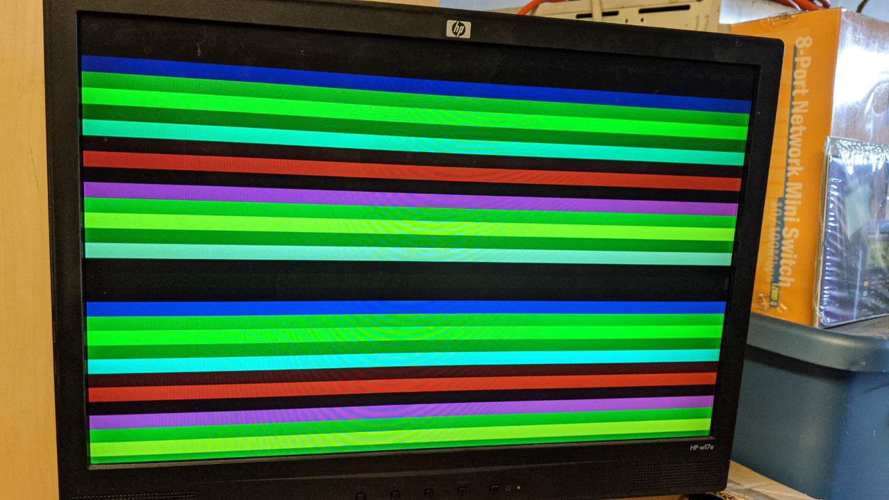
First, I hooked the RGBI outputs up to the vertical sync generator's character counter, to display horizontal color bars. At first, the colors were distorted; I thought that my resistor values were off (I just grabbed the closest values I could find to the ideal resistors). But, after fixing the hardware description to account for the display-enable signal, the colors fixed up nicely. Lesson learned: even though an LCD doesn't sling electrons at a phosphor like a CRT, you still need to blank the outputs so that the monitor has a proper black reference level.
![]()
(without blanking the video)
![]()
(with blanking the video)
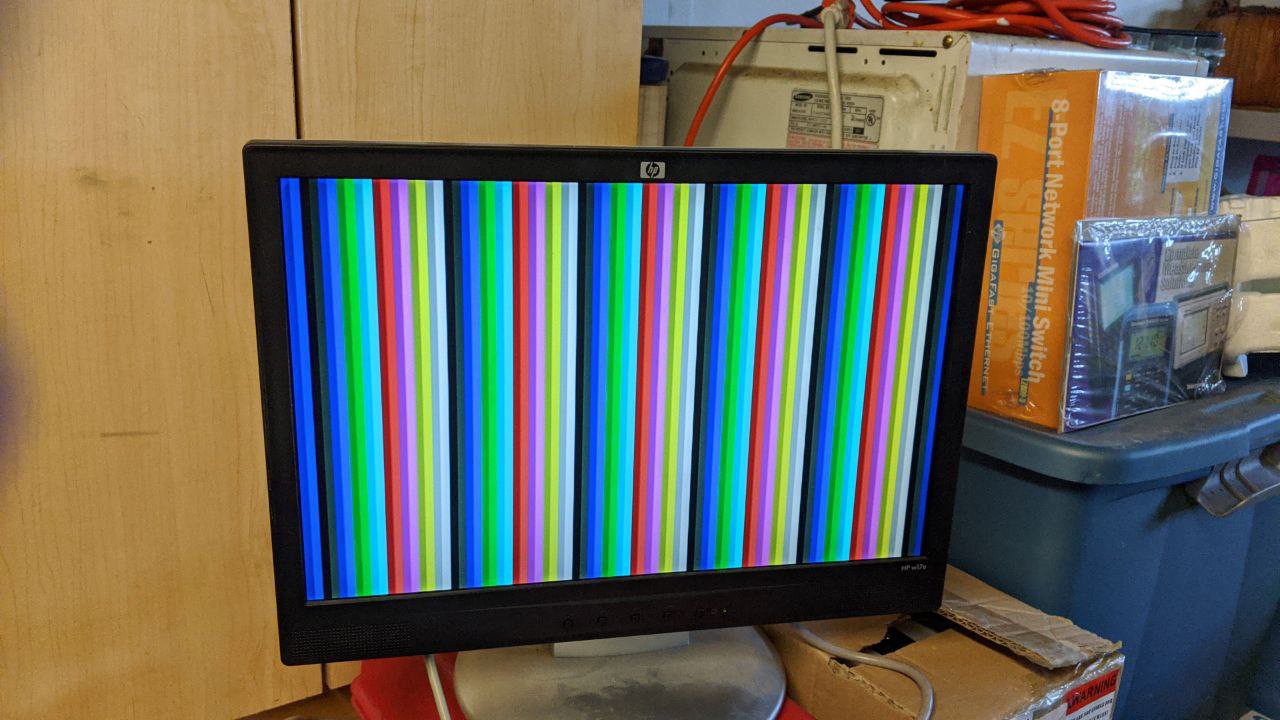
For funsies, I then rewired the RGBI outputs to show the horizontal character counter next.
![]()
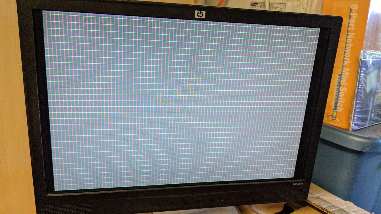
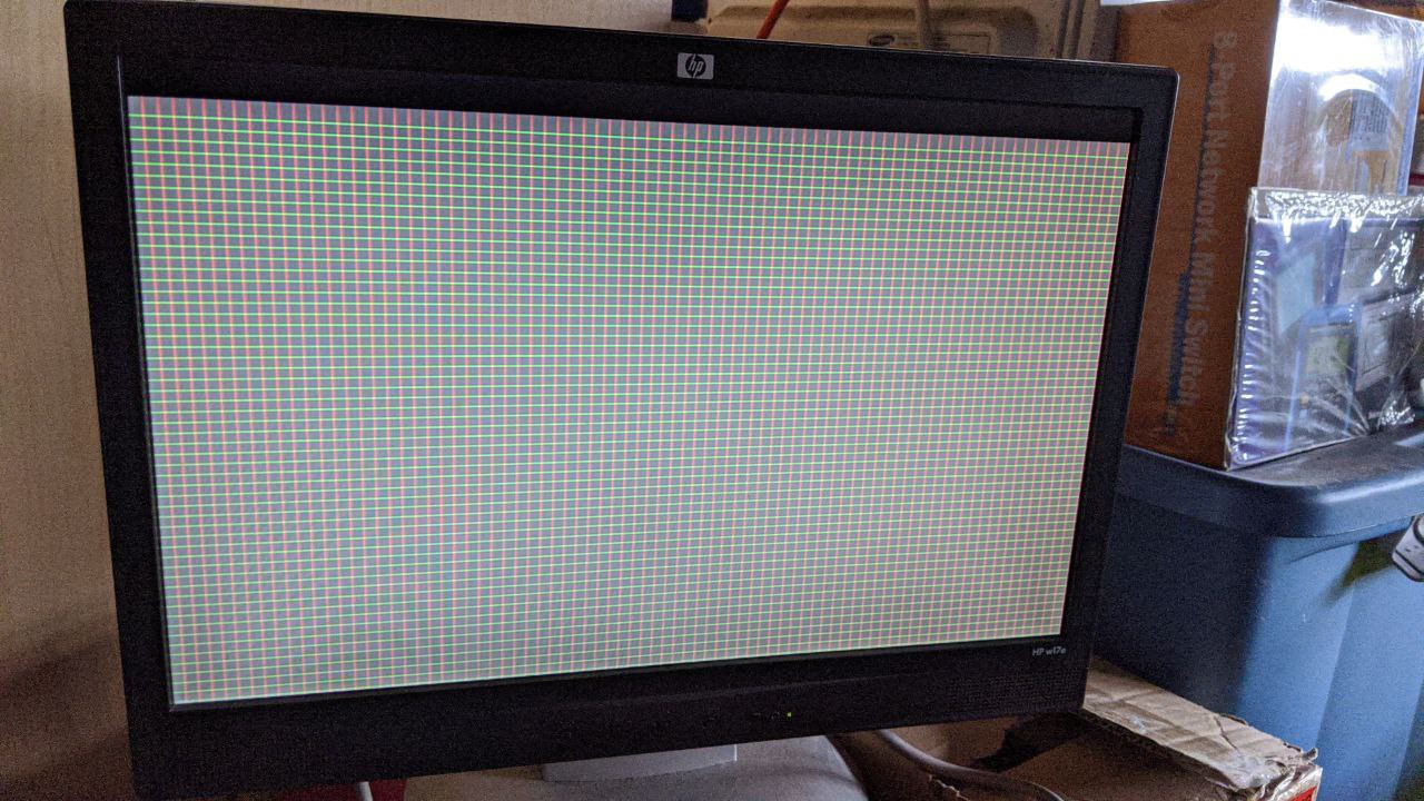
Finally, I decided to show the "character matrix" of the VDC output by tieing the red signal to the HSYNC generator's xclken output, and green to VSYNC's xclken output. The playfield will be illustrated by driving the intensity output. This results in a nice graph paper-like effect and it visually shows how several of the VDC registers interact. It's really neat to play with!
![]()
(80x30, using 16-pixel tall characters)
![]()
(80x60, using 8-pixel tall characters)
Sharp-eyed viewers might notice one final bug that needs squashing: notice the top row of characters is elongated? That's because the vertical total adjust circuitry does not negate the display-enable signal while operating. This is a very simple fix to implement.
BASIC Program to Initialize the CRTC
This program initializes the VDC's CRTC registers to produce an 80x30 character matrix display.
10 DATA 10
200 DATA 0,99
201 DATA 1,80
202 DATA 2,82
203 DATA 3,&h2C
204 DATA 4,31
205 DATA 5,13
206 DATA 6,30
207 DATA 7,31
209 DATA 9,15
222 DATA 22,&h78
1000 READ N
1100 FOR I=1 TO N
1200 PRINT I
1300 READ R,V
1400 OUT &H6E,R
1500 OUT &H6F,V
1600 NEXT I
To produce an 80x60 display, change these lines:
204 DATA 4,64
205 DATA 5,5
206 DATA 6,60
207 DATA 7,61
209 DATA 9,7
So, what of things like horizontal and vertical smooth scrolling?
Sorry to say; but, these features will need to be considered at a later time. Evidence now shows that Commodore engineers implemented these features outside the CRTC logic, so I'll have to also figure out how to do the same.
What's Next?
Right now, I think my next step is to implement the 16KB of memory needed to hold a character matrix or bitmap display, so that I can use that to start slinging pixels onto the display. This means I'll need to implement the infamous "busy" flag, along with registers R18, R19, and R31.
-
VDC Vertical Sync: One More Chance
04/24/2020 at 14:45 • 0 commentsI stumbled recently upon the data sheet for a MOS 6545 CRT controller and MC6845 CRT controller chips. I noticed that the vast majority of the sync-related registers map identically to those found in the 8563 VDC, which leads me to believe that the 8563 has a 6545 buried within it. So, if I start out building a 6545 clone first, I should be able to build the VDC in terms of the 6545.
Most importantly, the datasheet provides the timing diagrams I needed to understand how the vertical total adjust and such works, as well as how the internal counters work. H and V character counters are up-counters as far as I can tell, while "display" counters seem to be down-counters. All these extra counters I was needing appear to be functionality that is VDC-specific, and not CRTC-related at all. This is good to know, because I can factor functionality into more manageable pieces.
So, before I replace the VDC's CRT controls with those from the CGIA, I'll give the VDC one more chance, now that I know the foundation on which the VDC is built and have a datasheet for the 6545.
(I still think it's overly complicated, and I still think the CGIA's approach is simpler. However, I'd prefer to maintain as much compatibility as I can.)
-
Breaking Compatibility: HSYNC and VSYNC on VDC is Intractible
04/23/2020 at 21:37 • 0 commentsI'm seriously thinking about just throwing away the existing HSYNC circuitry, and switching from a character-column-based system to a pixel-addressed counter arrangement.
There are several events that need to happen along any given axis of a display:
Event VDC Register (Horizontal) VDC Register (Vertical) Blanking Starts. R35 (Display Enable End)
R22H (Horizontal Character Total)No equivalent. Sync Starts. R0 (Horizontal Total)
R22H (Horizontal Character Total)R4 (Vertical Total)
R8 (Interlace Control)
R9 (Vertical Character Total)Sync Ends. R3L (HSYNC Width)
R22H (Horizontal Character Total)R3H (VSYNC width)
R5?? (Vertical Total Adjust)
R8 (Interlace Control)
NOTE: R9 ignored here!!Blanking Ends. R34 (Display Enable Start)
R22H (Horizontal Character Total)No equivalent?? Or, R5?? (I can't tell!) Playfield Starts. R2 (Horizontal Sync Position)
R22H (Horizontal Character Total)R7 (Vertical Sync Position)
R8 (Interlace Control)
R9 (Vertical Character Total)Playfield Ends. R1 (Horizontal Display Total)
R22H (Horizontal Character Total)R6 (Vertical Displayed)
R8 (Interlace Control)With the 8563/8568 VDCs, these events are encoded in a variety of registers which, frankly, make no sense and makes for hardware which is significantly more complicated than it needs to be. It has taken me several weeks worth of study and a corresponding amount of experimentation with emulators to finally understand how to implement a compatible HSYNC generator, and to figure out how horizontal scrolling would work.
I've been trying to figure out a corresponding theory of operation for the VSYNC generator, but to no avail. It seems to defy any rational explanation. Despite the registers seeming to indicate they are common circuits under the hood, it turns out that there's enough minute edge- and special-cases that differ between HSYNC and VSYNC generation that they each would require their own formal specification.
I'm not sure I want to go down this rabbit hole.
It is especially weird that the VDC has separate registers for controlling blanking along the X-axis, but not on the Y-axis.
Contrast this with my CGIA concept, which I'd intended for use with the Kestrel-3 project. It uses pixel/line up-counters and magnitude comparators to trigger events. Horizontal control circuitry always works in units of pixels. Vertical control circuitry always works in units of raster lines. Both have a similar set of registers. No exceptions, and thus, no strange surprises. Plus, this approach directly supports features like raster interrupts, which are notably absent on the original VDC.
The other criticism I have of the VDC approach is its extreme reliance upon down-counters for almost everything, key word being "almost." In both X- and Y-axes, there are separate down-counters for specific purposes (e.g., to control the horizontal display enable, for example), but up-counters for other purposes (e.g., vertical smooth scroll depends upon a down-counter, but knowing which raster line to fetch for character font data depends on a corresponding up-counter that holds the same information.) This is incredibly wasteful of resources, to say nothing of how confusing it is to keep the design in your head.
In conclusion, although I'm satisfied that I've been able to figure out HSYNC behavior, I'm simply not able to crack the VSYNC behavior nut. I've spent weeks on this problem, but haven't gotten any further than defining how the display is generated without support for vertical smooth scrolling or the vertical total adjust. Without a coherent method of generating HSYNC and VSYNC, we can't get a stable display. For this reason, I'm deeply inclined to change the programming interface for the VDC-II away from VDC-style CRT control and replacing it wholesale with CGIA-style CRT control instead.
I really, really wanted to maintain backward compatibility with the VDC on this particular aspect. But, I see that is proving to be more expensive in terms of my time than I had hoped. Perhaps some external contributor can provide a compatible hardware definition in the future. For now, I think going with the CGIA CRT controls is the right choice for me.
-
Thoughts on Supporting Horizontal Smooth Scrolling
04/19/2020 at 21:41 • 2 commentsEver wondered why the C128's VDC has such a strange way of supporting smooth scrolling? I did, and I'm sure I'm still wrong, but I think I've gotten pretty close to the truth. Especially as my goal with VDC-II is to maintain backward compatibility where it makes sense.
What follows is a brain-dump, me rubber-ducking with myself, on this very topic. Enjoy!
While working on the VDC-II's generalized sync generator circuit, I realized that I needed to think about how smooth scrolling works. This project log aims to record my current thoughts about how the 8568 implements this feature. DISCLAIMER! This information is hypothetical, even speculative in nature, based on the documentation found in the C128 Programmer's Reference Guide and on observations of how VICE and the Z64K emulators behave when I twiddle VDC register bits. I still don't have actual hardware to test with.Let's focus on horizontal smooth scrolling, since it's actually the *harder* of two axes to consider.
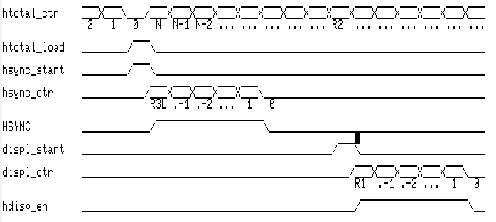
It all started when I started to focus on the horizontal sync position register (R2). It became clear to me that the horizontal total register (R0) is the reload value of a down-counter. The HSYNC pulse down-counter is reloaded (with the lower 4 bits of R3) when the horizontal total down-counter reaches 0, while also also reloading the down counter with the value in R0. (In case you're wondering, the HSYNC pulse is asserted as long as the horizontal sync down-counter remains non-zero.) When the value of the horizontal total down-counter is equal to the value in R2, *another* down-counter is reloaded with the horizontal displayed value (R1). As long as the horizontal displayed down-counter remains non-zero, a horizontal display enable signal remains asserted. This is how the VDC knows where the playfield appears on the screen, and how it can assert its borders.
The following timing diagram helps illustrate what I've discussed above. Signals in all-caps are signals you'd expect to find exposed to another circuit; lower-case signals are implementation details to the sync generator circuit.
![]()
This is sufficient to generate, for example, a solid block on a display. However, there's more that must be considered when looking at supporting horizontal smooth scrolling.
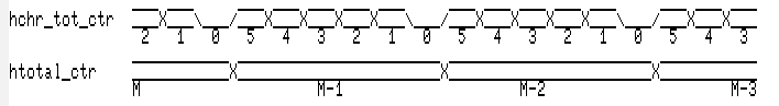
The counter values above are in units of characters, not in pixels. Within each character column, there are some number (configurable via the high half of R22) of pixels, with 8 pixels being maximum. This character dot counter is also a down-counter, as far as I can tell from the available documentation. Thus, we expect to find timing similar to this (assuming 6 pixels per character cell):
![]()
(If you've ever wondered why the VDC keeps asking you to subtract 1 from things here, and add 1 to things there, this is why. This is also why you must reprogram the sync generation registers whenever you change the number of pixels in a character.)
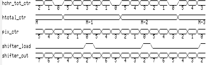
In order to support smooth-scrolling, however, we need yet another counter. This one is programmable from the lower half of R25. When this counter reaches zero, then we know to reload the pixel shift register. Based on how the character data is laid out in the VDC documentation, the shifter always draws its video data from the most-significant bit of the bitmap byte; in other words, bit 7 is always shifted out, then bit 6, etc. for as many bits as is configured to exist in a character cell.
![]()
I think the original VDC would have also used shifter_load to trigger a memory fetch for the next character as well. It'd involve three fetches:
- Fetch the next character matrix byte.
- Fetch the next attribute matrix byte (if attributes are enabled).
- Fetch the character font byte for the character fetched.
Assuming these fetches take one dot-clock to complete, that implies that the minimum character width is 3 pixels if attributes are enabled; 2 otherwise.
Since the VDC-II is intended to work with modern memory architectures, which strongly favors streaming over random access, it will work a bit differently. The assertion of the HSYNC pulse will trigger a sequence like the following:
- Fetch the next HDISPLAY character matrix bytes into a holding buffer. (Bad-line only.)
- Fetch the next HDISPLAY attribute matrix bytes into a parallel holding buffer. (Bad-line only.)
- For each byte fetched into the character holding buffer, fetch the character font byte for the named character into a line buffer.
It's regrettable that I'll need a bad-line mechanism, but that is a constraint put on me by external factors that I have no control over.
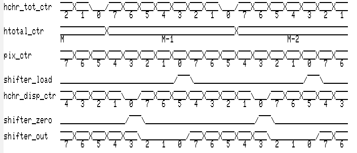
Getting back to the smooth-scrolling support, remember that characters can have fewer pixels displayed than exist in the font data. Here's a hypothetical situation that we find in the Commodore 128 Programmer's Reference Guide: 5 pixels per character but an 8 pixel character cell width. We might want to have another display enable signal that operates on a character column basis. Alternatively, and I think this is most reasonable, command pulses that zeros the shift register (which has the same effect as a dedicated enable).
According to the VDC docs, if your character cell is wider than the number of pixels in a character, then to smooth scroll, you not only adjust the smooth-scroll register, but also (strangely) the horizontal character display total register as well (bottom half of R22). In the example above, R25 would be set to 4 (which is why pix_ctr is 4 after restarting the character boundary), but for some reason, you want to set the character total register to 1. Why is that?
It's never explained in the PRG; but, the reason appears to be that the character display total and horizontal smooth-scroll registers are both synchronized against the character total register reaching zero. At the start of a character cell, the character total counter (yup! Another counter!) is set to the horizontal character displayed value (R22), and counts down. When that counter reaches zero, we negate the character display enable/zero the shift register.
![]()
So, in this bit of rambling, I think I've satisfactorily figured out how to implement horizontal smooth scrolling in a manner compatible with the original VDC chip, and explained why the registers behave as they do. It's definitely not how I would have designed the hardware, but at least I now have an understanding of how to implement more of the VDC-II's logic.
-
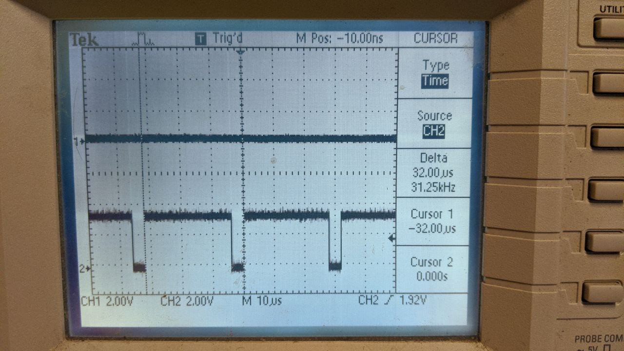
First HSYNC Pulse!!
04/18/2020 at 16:53 • 0 commentsAfter installing the new 74LVC8T245 level shifters into the circuit and reprogramming the FPGA to drive the DIR pin (which I've labeled A_B, because I can never remember which side of the bus is driving when it's high or low), I'm happy to report that the RC2014 booted fine.
I dropped into MBASIC from CP/M, and typed the following:
OUT 110,0:OUT 111,99
OUT 110,2:OUT 111,87
OUT 110,3:OUT 111,12
OUT 110,22:OUT 111,&h78
First line tells the VDC-II that there are 100 characters in a complete scanline. The second tells the VDC-II where the start of the HSYNC pulse resides on the scanline. The third sets the HSYNC pulse width. Finally, the fourth tells the VDC-II that there are 8 pixels per displayed character with no inter-character fill.
And I was immediate greeted with the following display on the oscilloscope:
![]()
This tells me several things all at once:
- You can interface to a Z80-compatible bus using 3-flop synchronizers clocked at 3.3x the Z80 bus frequency, without needing a dedicated bus clock input.
- TXS/TXB-type level shifters are not the correct type of level shifters to drive any kind of real bus, backplane or otherwise. They seem to be most useful for point-to-point circuits only; but, then, those are exactly the kind of links where not having a direction control is not a useful advantage to have. It's not clear to me what market TXS/TXB level shifters are intending to penetrate.
- 74LVC8T245 chips are powerful enough to drive a Mack truck, and fast enough to keep up with a Ferrari. Just make sure you set the DIR pin correctly.
- I really can solder SMT components without specialized equipment.
- nMigen rocks. TinyFPGA BX rocks. Based on my experiences with these tools, you can bet I'll try building more ambitious projects with this gear in the future.
-
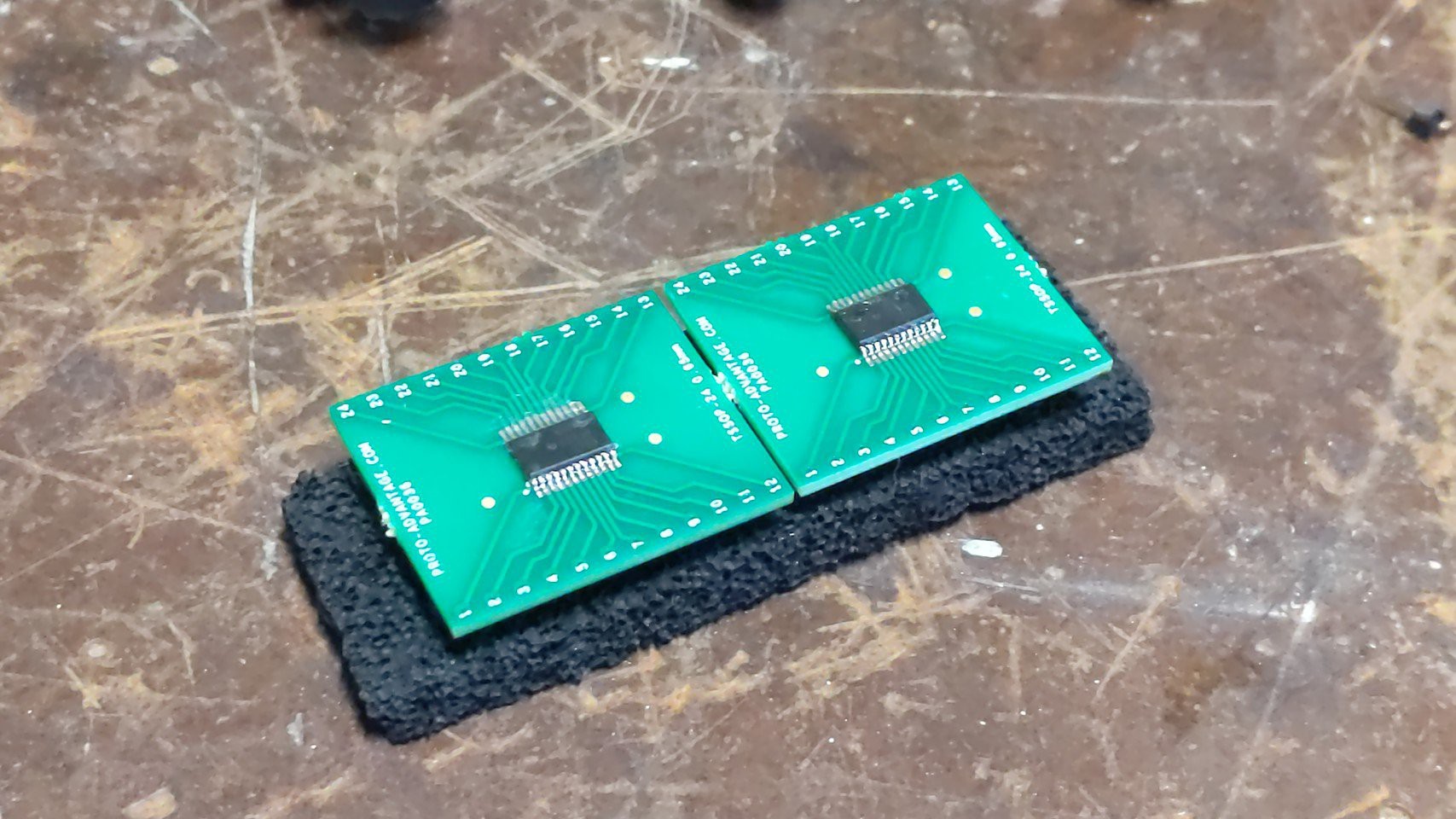
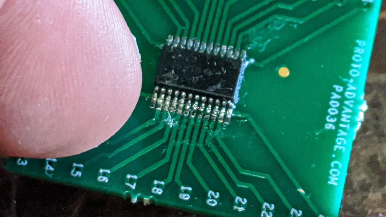
74LVC8T245PWRs Have Arrived
04/14/2020 at 15:36 • 0 commentsMy collection of 74LVC8T245PWR chips have arrived. These are 24-pin TSSOP chips which I had to build my own break-out boards for. That was frustrating (especially as I'd never soldered SMT parts before); but, I was nonetheless successful. Continuity checks indicates no bridges, shorts, or open circuits, so these ought to work out nicely.
I've already updated the circuit schematics to include these new chips in the design. I lost steam after rendering the schematics, but hoping to wire them into the circuit this-coming weekend.
![]()
![]()
-
Still Waiting ... In the Mean Time...
04/06/2020 at 15:39 • 0 commentsWhile I wait for the 74LVC8T245 chips to arrive, which seems like it'll be forever thanks to a certain virus, I've decided to try and use my spare TinyFPGA BX as a test harness for the VDC-II.
This means resurrecting the Kestrel-2, but in a reduced form, as the TinyFPGA just doesn't have the same resources that the Nexys-II's FPGA (Spartan 3E as I recall) has. The first step towards targeting this chip, though, is rewriting the CPU into nMigen, a process which I've already begun and hope to finish soon.
-
Z80 Bus Interface Works . . . Maybe.
03/30/2020 at 04:30 • 0 commentsAfter building the initial circuit for the VDC-II "chip" (a TinyFPGA BX programmed with the VDC-II core in progress), I was greatly disappointed to learn that it did not work once I placed the FPGA in-circuit. Until that point, everything worked great. But, once the FPGA was in-circuit, the level shifters started to behave with wild abandon. So much so, in fact, that the RC2014 computer I'm using refused to boot.
The data bus had wild, 50-52MHz oscillations on them, crazy amounts of overshoot and undershoot at times, and you can clearly see where the one-shot circuits of the level shifters would start and stop. All in all, the logic levels were not clean, and I'm convinced the Z80 and/or memory on the bus refused to have anything to do with this nonsense.
Here's the schematic (PDF) of the current circuit.
After taking the TinyFPGA BX out of the circuit, I decided to just test it by hand, the good old fashioned way: strap a bunch of pull-down resistors on all inputs, and selectively use wires to +3.3V to raise them high when needed. I'm happy to report that, as I type this, the VDC-II core (such as it is) seems to be able to accept and return bytes via the Z80-side of the interface.
In theory, I could have programmed the chip sufficiently to actually start generating an HSYNC signal. However, I didn't bother going this far; manipulating the bus interface by pulling and setting wires in the breadboard was terribly exhausting on its own. Maybe tomorrow; or, I'll just wait for the new level shifters to arrive instead.
VDC-II
Commodore 8568-inspired (and mostly compatible) video core for driving VGA-type displays.