-
1Find a used Leitz Prado 250/500
Leitz was a German company that built optical devices such as microscopes and slide projectors. These slide projectors were quite expensive at the time they were built (a worker had to work one month to buy one in the 1950s), but they are worth it: there are still many of them around on Ebay for a few bucks, most of them working.
We want to keep the optical system but want to scrap the electrical components. So you can buy a Leitz Prado without a bulb or generally faulty, but you need all optical components. To make sure you have everything, you can take a look at the Link from Pradoseum, a virtual museum dedicated to Leitz Prado.
Leitz Prado 250 and 500 only differ by the bulbs that were used, but the Leitz Prado 250/500 were changed a little over the years. If you can, try to grab one with a ventilation channel at the front, it will make things easier. Do not buy a Leitz Prado 150 or something, it's completely different. The Leitz Prado 750 is quite rare, but you can use it, too.
Do not buy any "special edition", we need the very basic dia slider.
![]()
-
2Remove all parts
Do not switch the projector on! Most electronic parts are rotten and pose the risk of electric shock. Just leave as it is, we will replace the system.
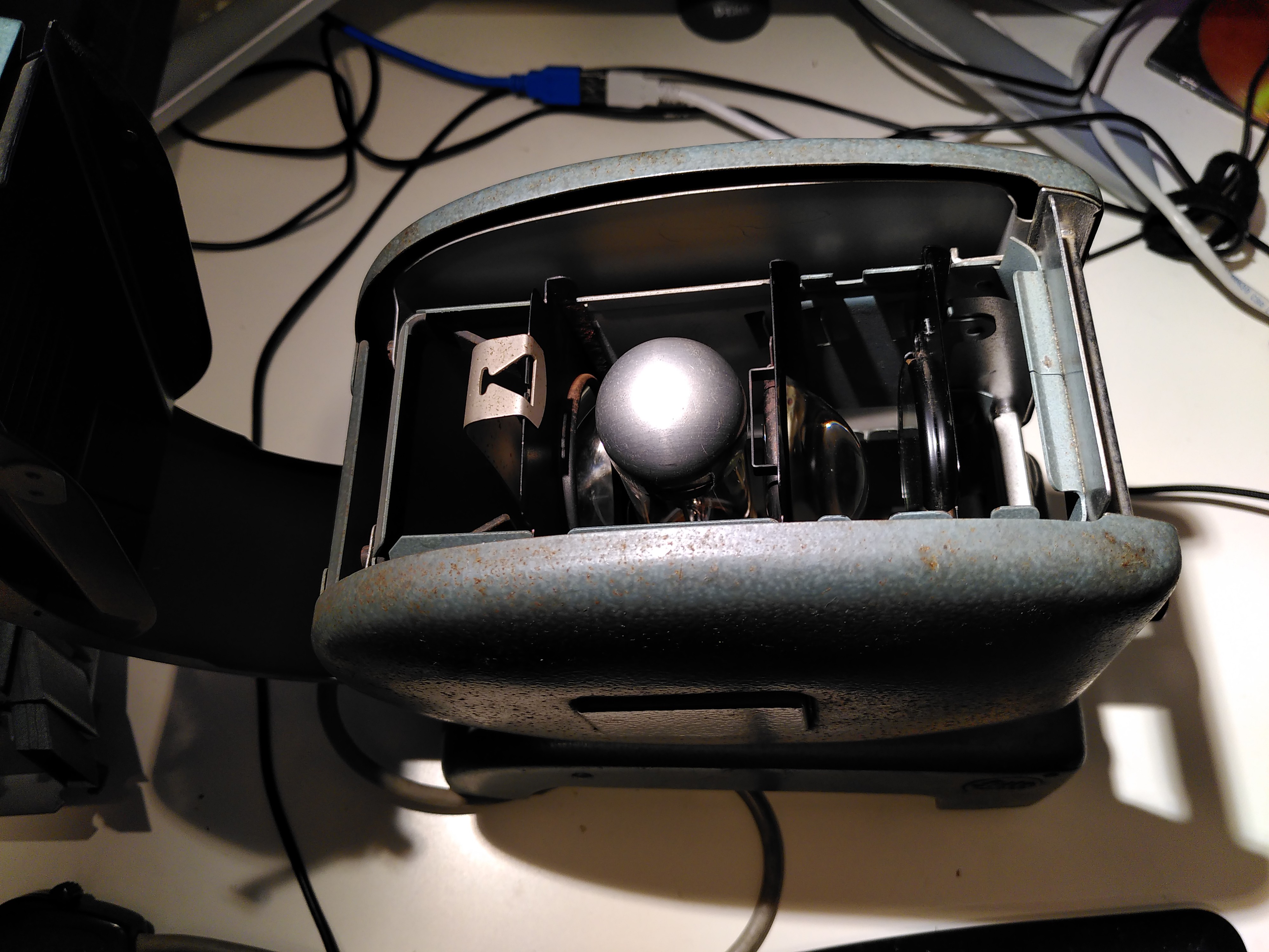
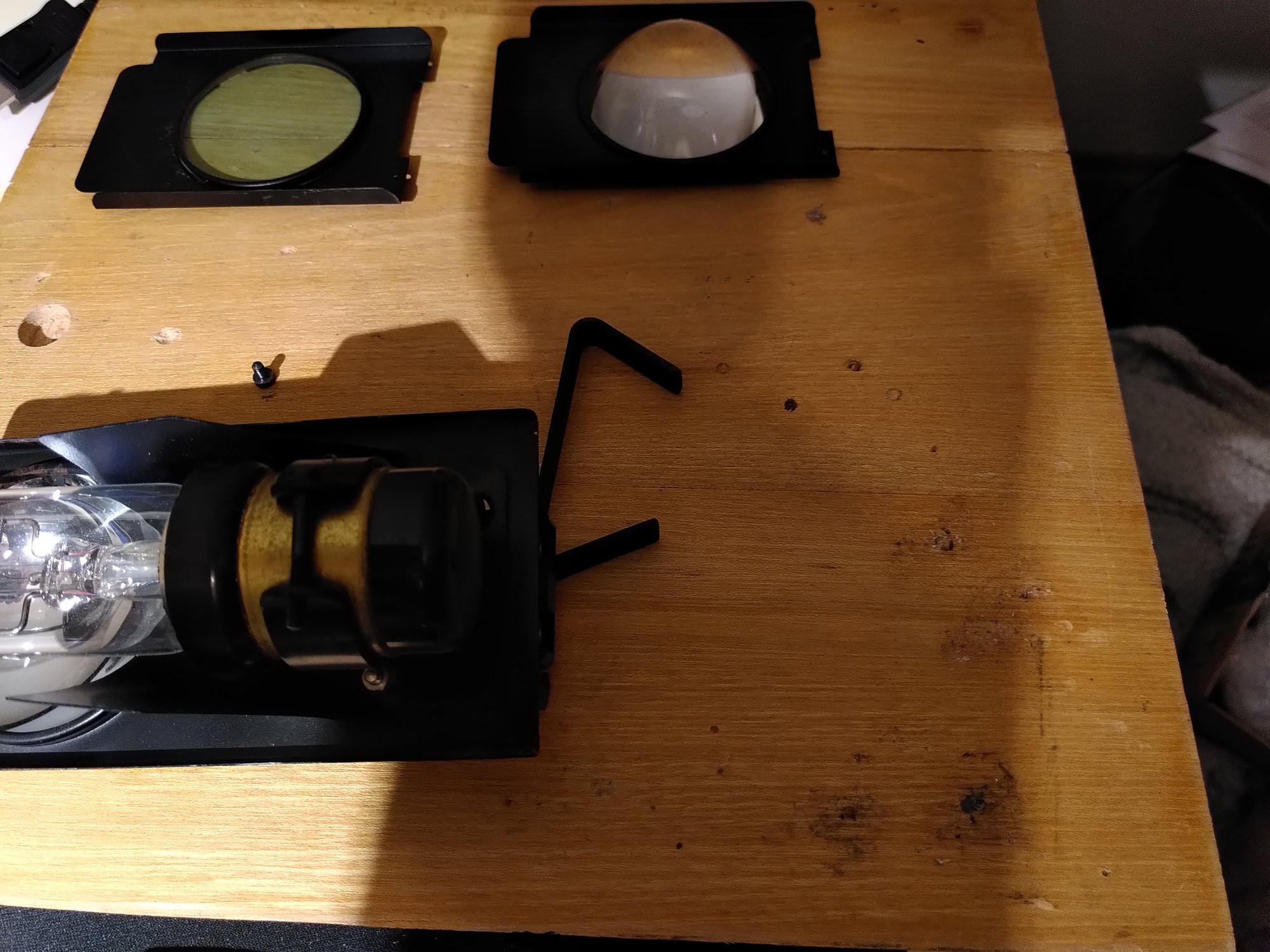
Open the projector at the top and remove the bulb including the holder, the condensor lense and the heat filter (the other thing inside).
![]()
Try to unmount the objective (the large thing that looks like a cannon), so working is easier.
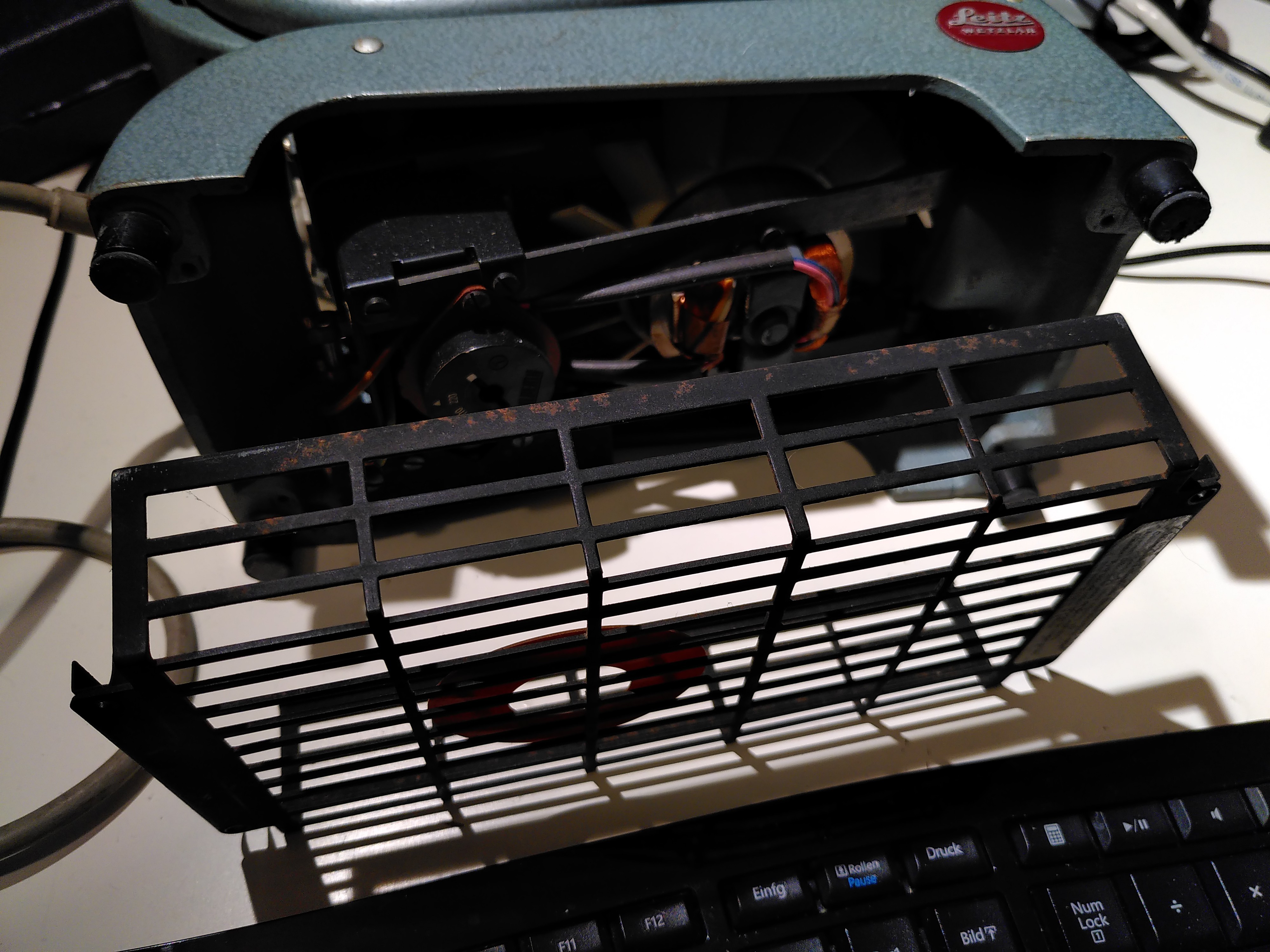
Turn over the projector and clear out the "cage" on the bottom. Unscrew the bottom (keep all screws, of course) and remove all electronic parts. Please note that you only need to unfasten two screws in the front. The rear is a sliding mechanism.
![]()
This is the first time you have to let go, you need to cut the AC cable. You have to do it to remove the cooling system. There is a lot of space for your ideas like a Raspberry Pi or something in the cage.
-
3Mounting the LED
The LED produces a lot of heat, so you need a cooler for that. The best fit are rather small CPU cooler with a 60mmx60mm fan. The height of the heatspreading element should be around 30mm. Socket-A or Socket-462 boxed cooler kits are best fit for our project. Avoid anything special or round. Unfasten the screws of the fan and keep the parts.
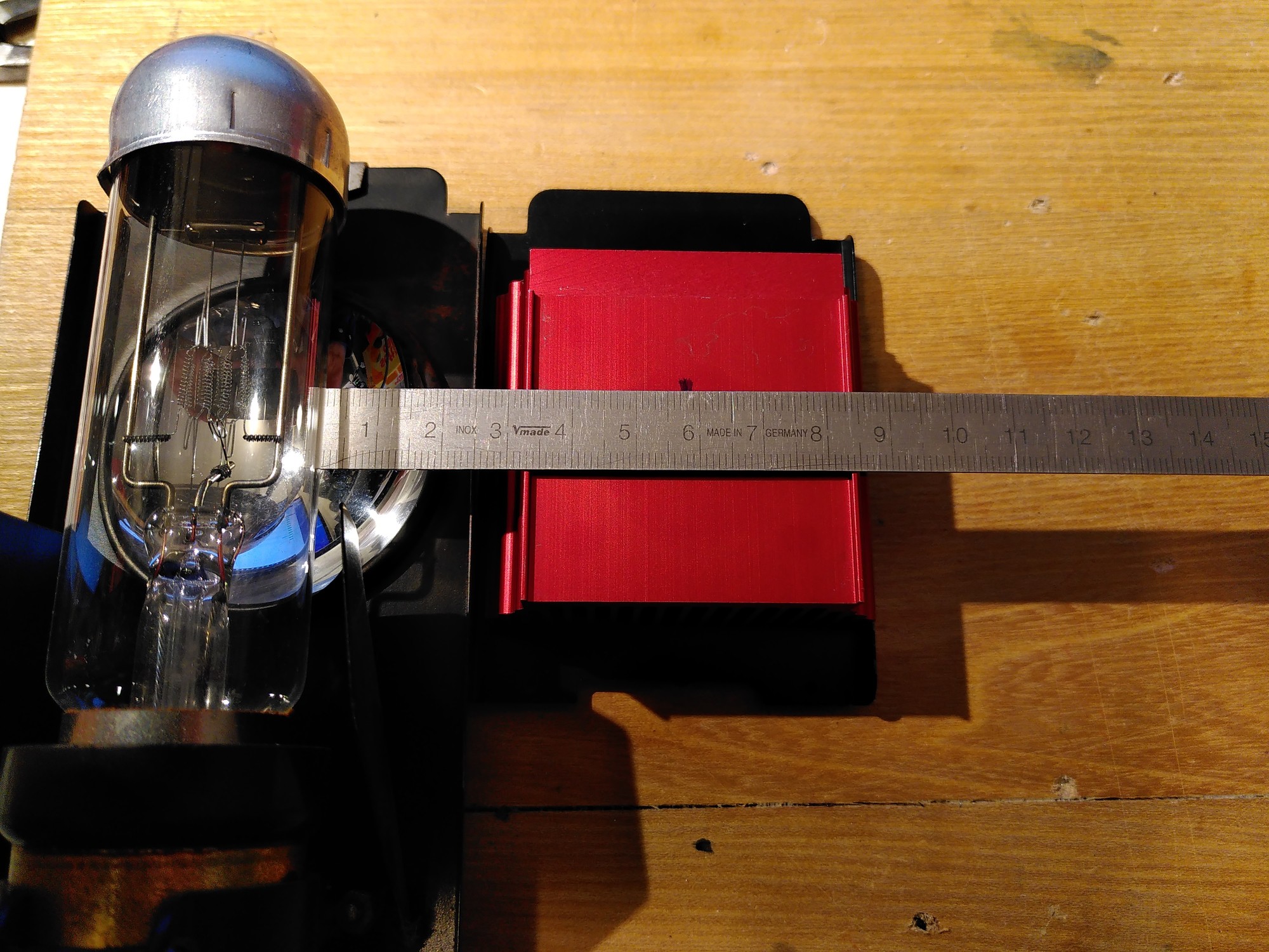
Now we need to mark the position of the LED onto the heat spreader. Take the bulb including the holder and the heat filter and place it next to each other with the top aligned. Put the heat spreader onto the heat filter centered and in a way that the glass is completely covered and the spikes are vertical (thus not blocking the airstream). Make a vertical marker exactly in the middle of the heat spreader.
![]()
Take a water proof marker and mark the position of the bulb's coiled filament on the heat spreader. Be as accurate as possible with this, a very small misalignment will cause a significant decrease of brightness.
Do not mount the LED by now to avoid damage to it (I had to try some things, so I have it mounted in the pictures, but you should not do it).
-
4Put the parts together
Scrap all parts off the bulb holder including the wing-like metal airflow thingies (you will have to be a bit rough and break that parts) and the mirror.
You should by now have a clean metal slate with a large hole on the top and some smaller holes on the bottom.
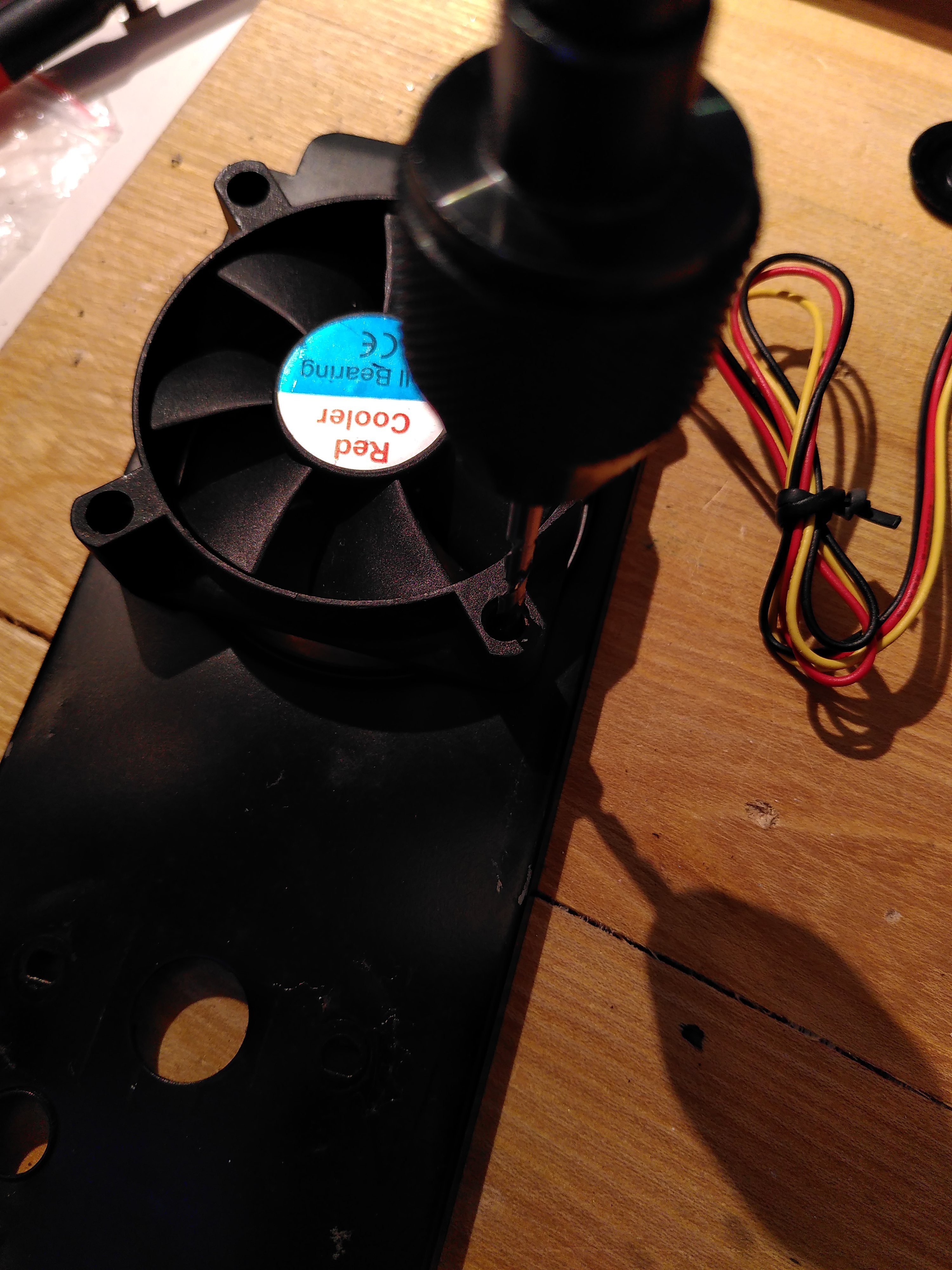
At first grab a 3mm drilling tool, take the fan, center it onto the large hole on the top and drill four holes.
![]()
Now put the heat spreader on the opposite of the fan and take some larger screws than the original ones (3mm, I used screws intended for wood). Make sure your heat spreader is in the right direction and not somehow rotated, then fasten it using the screws.
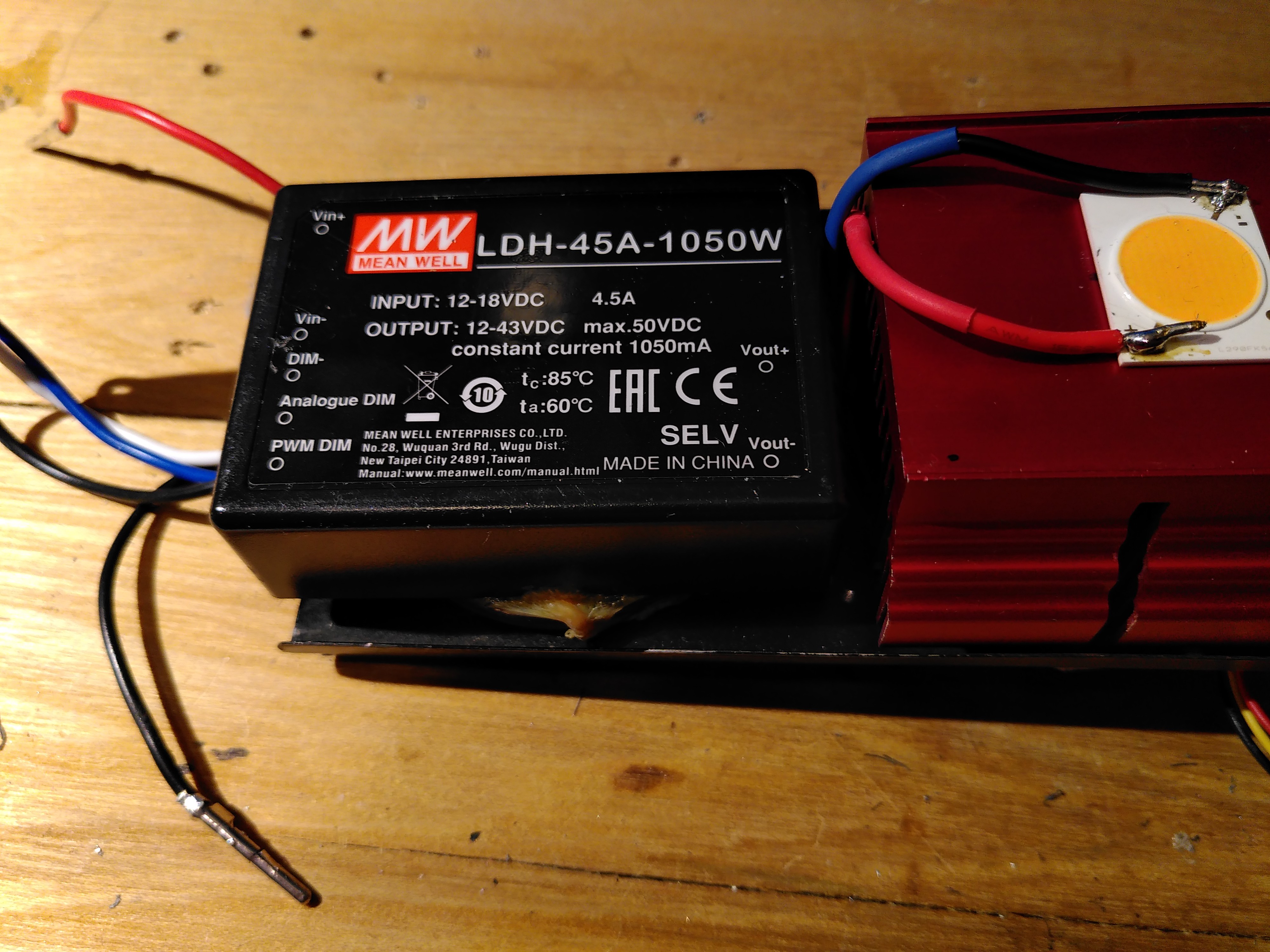
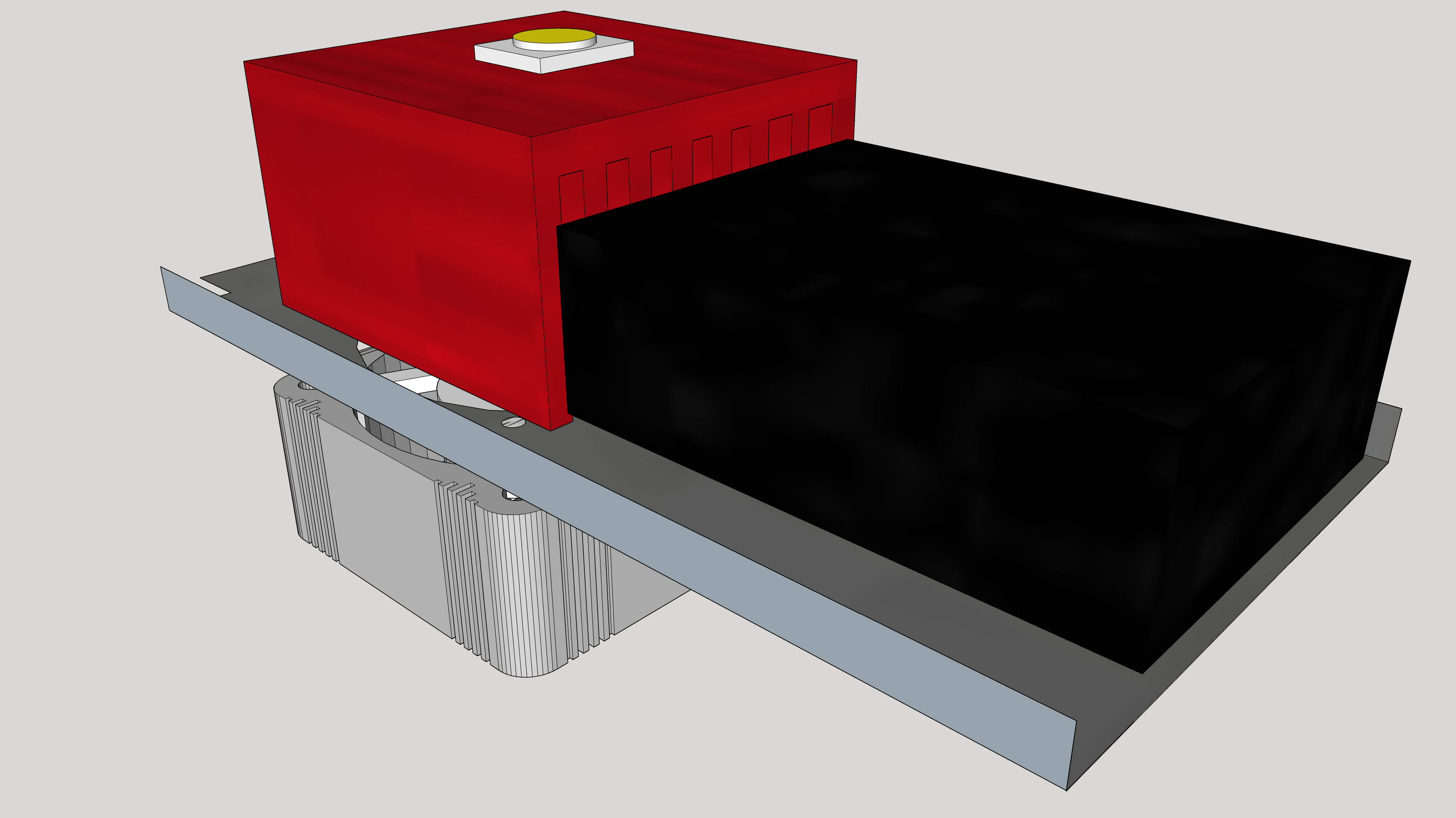
The next step is a little tricky - take your time. You need to mount the LED driver unit (the black box with some cables) to the slate. It is exactly as wide as it could be to fit, so make sure everything you are doing is pretty much accurate.
You need a spacer (1cm is best) to put under die LED driver unit to elevate it. I used the glass plate from the heat filter, which was ok, but not the optimal solution. So if you have, find a piece of metal, for example.
TheL ED driver needs to have the side with the two cables directed to the top and with the five (input) cables on the bottom. Put the cables on the bottom through the holes.
Glue the spacer onto the heat spreader side of the slate and the LED driver onto the head spreader. Make sure it is as centered as possible and you have a little distance between LED driver and heat spreader. I ussed Pattex Glue which was a good decision, but takes some hours to become resilient.
It should now look like this (without the LED, though):
![]()
![]()
-
5Electric wiring/soldering (Part 1: everything beside the LED)
![]()
After some failed tries with pre-built Coaxial Power Connectors from China, I decided to go for Molex-connectors known from computer power supplies. Please be careful: most Y-cables you can buy on Ebay are not made for the high current we are using - most of them had such a R the whole thing wouldn't even start, one cable got very hot. So I decided to use only one Coaxial Power Connector to the outside and use Molex for the inner wiring.
You should use connectors instead of wiring everything directly so you can remove parts for cleaning/maintenance. You don't need use connectors, though.
At first we need to solder the Coaxial Power Connector. It will be located in the notch at the back, which was formerly used for either power cable or the power connector. Versions of the slide projector differ, mine had a fixed power cable and two holes drilled. Older versions have a detachable power cable and no holes, so you might need to drill two in that case, right and left of the notch.
You can decide which material to use to fill the gap - I have printed a thing for me (find it in the links), but you can use an old piece of plastic (a CD cover or something), just somehow get a hole in it.
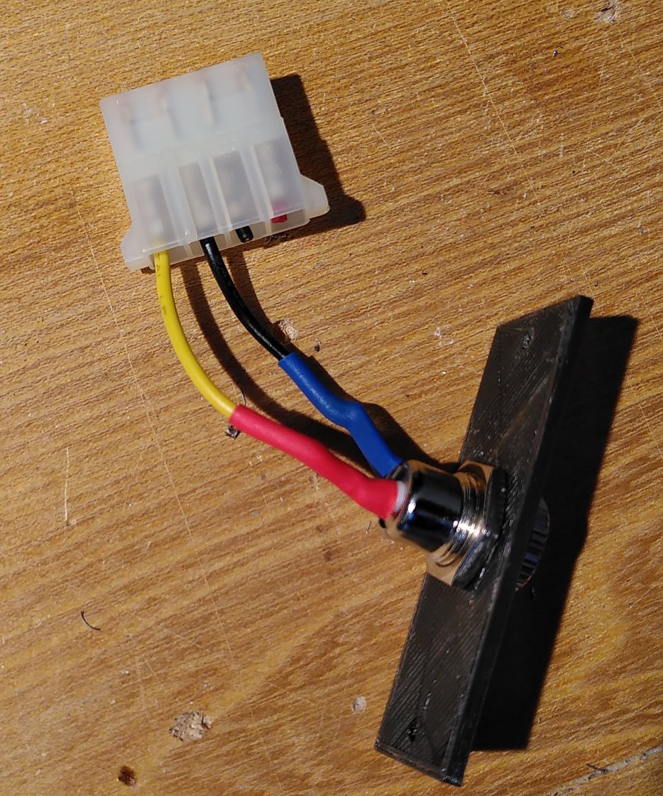
Now cut the Molex male power connector from the ATX power supply with a short (7cm or so) cable still attached. You can remove the red wire and the black one next to the red wire as they are for 5V, which we don't use.
Pull the cable through the aforementioned plastic thing and solder the Coaxial Power Connector to it. Yellow is the middle pin (+), black is the outer pin (-). Make sure you have the cables pulled through the nut before soldering. You should use Heat-shrink tubing on both pins to insulate them and reduce mechanical stress.
![]()
The fans will be connected to a pre-built adapter, so no need to solder that thing.
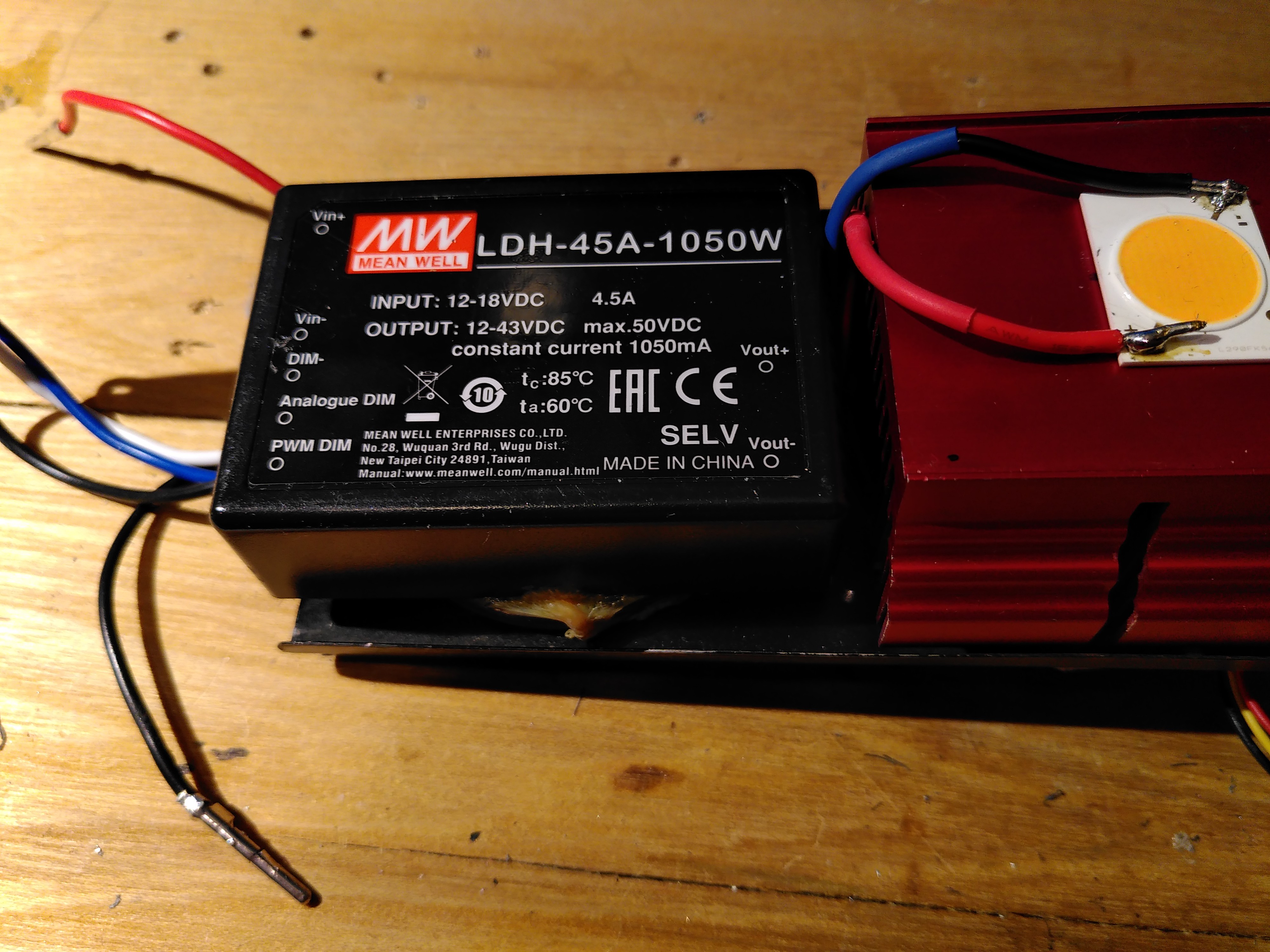
Find the power inputs (Vin+ and Vin-) of the LED driver and solder it to the female Molex connector (12V) (sorry, I don't have a good picture of that).
-
6Electric wiring/soldering (Part 2: the LED)
Now it's time to solder the LED (or more accurate a Chip-on-Board, I will refer to it as COB).
At first, take the adhesive glue and glue the COB onto the heat spreader at the position you have marked earlier. Wait some time (an hour or more) for the glue to become hard. You can do the soldering with the COB not glued, but it's easier when it is in position.
In the meantime, prepare the cables for the connection from the LED driver (Vout+ and Vout-) to the COB. To avoid thermal and mechanical stress, you should put heat-shrink tubing around them.
Now solder the cables to the COB (note the + and - marking). Put some solder onto the COB and some onto the cables and solder the cables to the COB.
![]()
Before mounting everything, you should test the whole installation.
Important: the COB is extremly bright and will damage your eyes if you look into it. Turn the COB away from you while testing and make sure no one is around.
Put all Molex connectors together and attach the power supply. The COB should turn on and the fans should start rotating.
If they do not, detach the power supply immediatly and search for problems.
If the COB turns off and on frequently, the power supply is too weak. The LED driver will draw 4,5A. Fans need a higher current to start turning, so you max out the power supply's specs. Mine didn't turn on if AC was connected with DC already connected to the slide projector.
-
7Mount everything
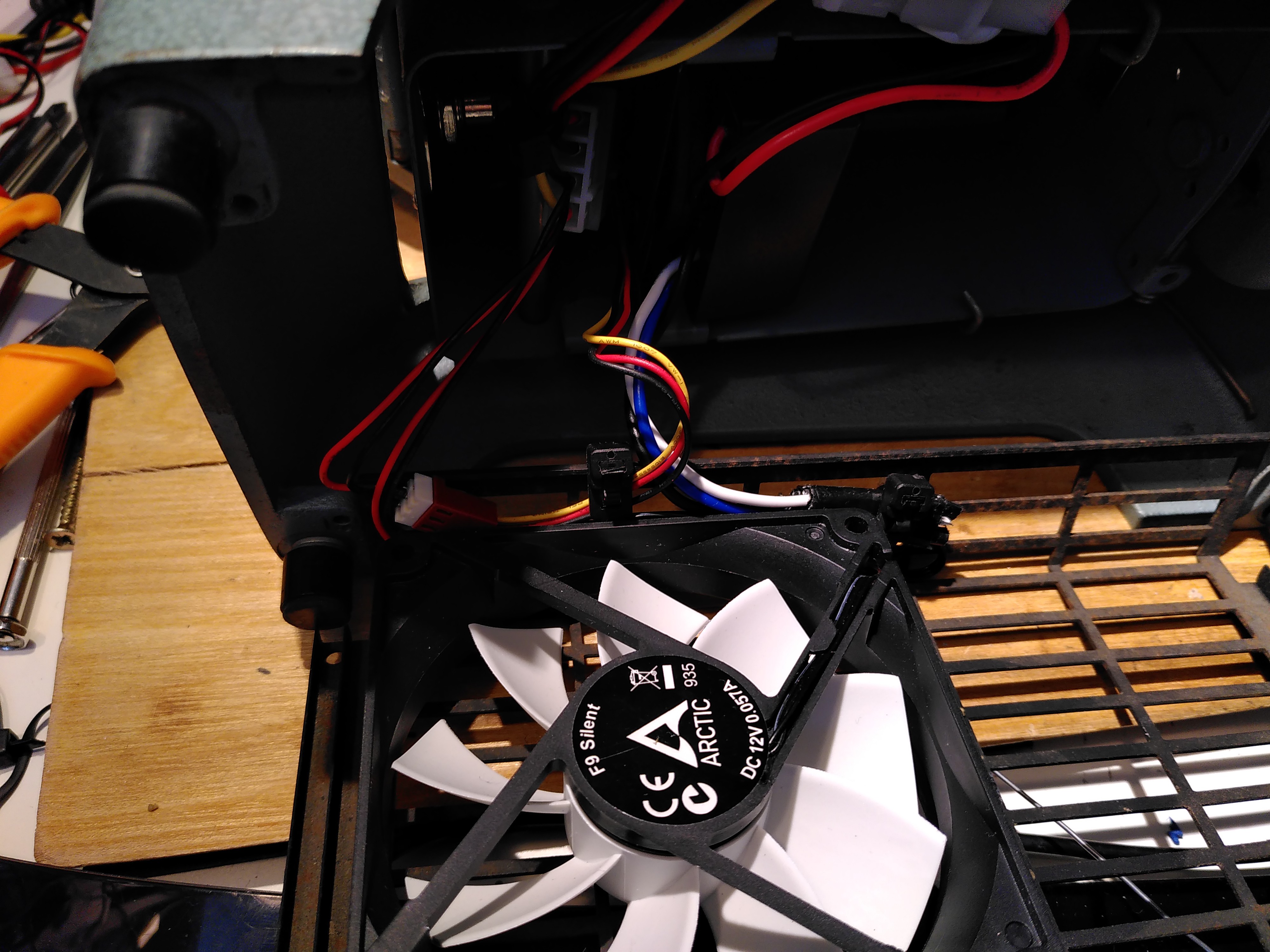
Take the 92mm fan (80mm is ok, too) and mount it to the cage with its screws. You might need the slates to do this. Airstream direction needs to be upwards (to the COB).
Mount the plastic thing to the back of the slide projector. Remember you might need to drill two holes to do so.
![]()
Now slide in the former bulb holder in its position. If the heat sink is too wide to fit, use little force to push the sides apart.
Do the wiring. Make sure you use cable straps to avoid cables stopping the fan.
![]()
The last step is to mount the cage (remember: you only had two screws as the other side was slid in; either get two additional screws or live with it ;) ).
-
8Use your slide projector (and do something more)
Have fun using your new energy efficient and safe slide projector.
Remember: never use it without supervision or on non-solid surfaces (sofa, bed) - high current and high temperature are nothing to be left alone. Use it on your own risk!
I will make another project to show you how to convert the slide projector into an even cooler Retro LED beamer.
Thanks fly out toe ikaruga666 for the idea (find the thread here: https://www.ledhilfe.de/viewtopic.php?t=23448). If you are interested in dimming the LED driver, there is an wiring diagram to do so.
Upgrades could be:
- dimming the LED driver
- a thermal fuse to avoid overheating
- measuring the temperature
- an electrical fuse
- Beamer
Retro Slide Projector "Green-Edition"
Exchange your old slide projector's massive bulb for a energy-efficient ("green") LED
 Stephan Goedecke

Discussions
Become a Hackaday.io Member
Create an account to leave a comment. Already have an account? Log In.