Close
0%
0%

VISP - Ventilator Inline Sensor Package

Bidirectional flow (volume), pressure, and temperature sensing in a single inexpensive I2C/SPI package.

Similar projects worth following
Utilizes commodity barometric pressure sensors combined with a small 3D printed inline coupler for monitoring an airstream.

The absolute pressure values provided by three of the barometric sensors are converted to relative by using a fourth at ambient as a reference.

One sensor reads the ambient pressure, and temperature of the room.
Two sensors are positioned in an S type pitot tube for bidirectional volume/flow measurement.
The remaining sensor provides relative pressure and temperature measurement.

Good resolution with 24 bit sampling.
22mm Female/Male inline connector for common tubing.
120Hz update frequency
Optional onboard eeprom for storing calibration data.
I2C version 3.3v or (optional) 5v tolerant.
SPI version in the works.

About $20 US, half that cost at volume.

@Steven.Carr has designed new BMP388 boards to be our last generation and official board for the VISP.   Boards are currently out for quote with ScreamingCircuits.com for fabrication and assembly.

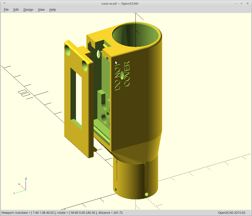
The 3D model matches the boards and the prints are pretty consistent.  The overhang for the board area for FFF may need to be a little more gentle: at normal speeds it can get messy.  Looks great using SLA

For FFF, this was rendered out to use a 0.4mm nozzle, 0 walls, all infill, concentric.  This results in a better print as then the printer only leaves the solid area once per layer to jump to the middle 'break off' support for the lower pitot tube.  When I say rendered out for a 0.4mm nozzle, I mean that critical wall thicknesses are an exact multiple of the nozzle size.  If you want to use a different nozzle, it would be much better to adjust the model and render again to keep this trait.

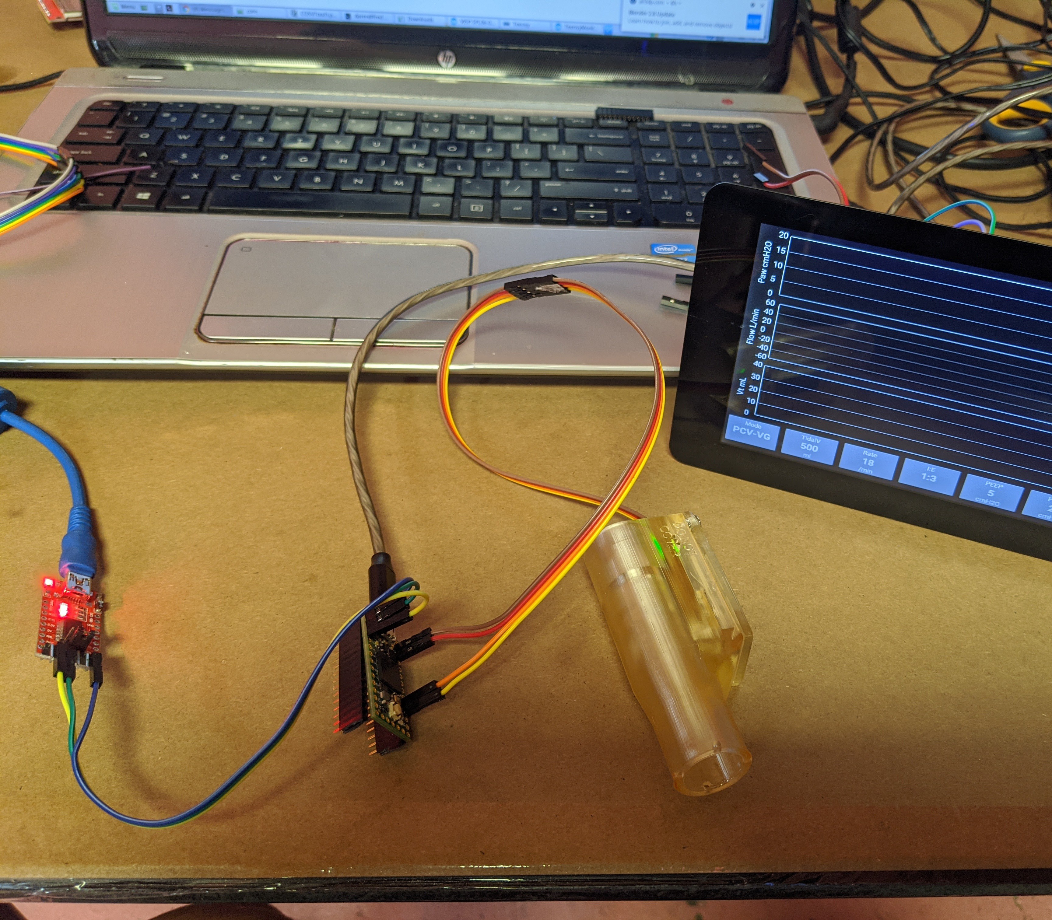
We have moved to a venturi style orifice and have verified the fit of the PCB and piggy back LCD for on mask feedback.

A ventilator sensor shortage is brewing... 

Subproject of #COSV - Cam Open Source Ventilator 

  • New Sensor Boards

    Steven.Carr09/18/2020 at 15:21 0 comments

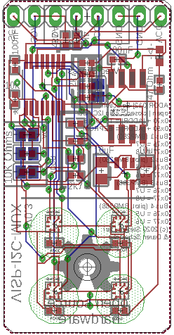
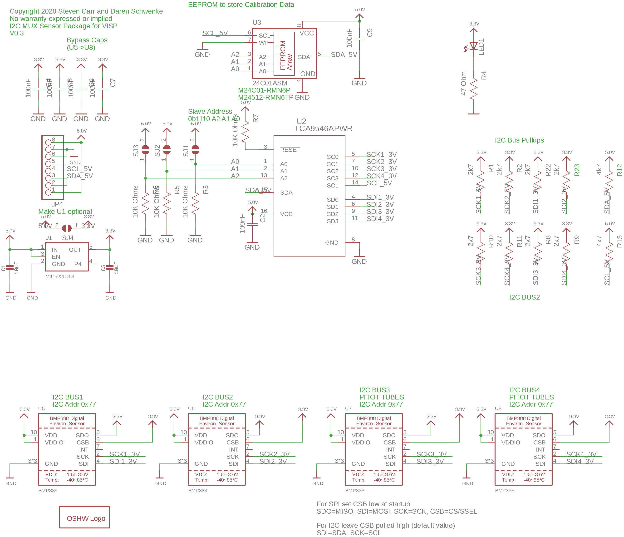
    New single channel I2C PCB's have been designed.   These boards use only the BMP388 sensors and each sensor is on a seperate I2C bus behind a TCA9546APWR.   An initial batch was ordered from @oshpark  and were hand assembled by @Steven.Carr.   Out of 9 boards, only 3 were successfully assembled.   Getting the solder paste right is crucial and is extremely hard to do with such small pad sizes.    Not to mention placing the parts with a home made manual pick and place rig.   Only 3 PCB's is not enough to distribute to the rest of the team, so we are currently having ScreamingCircuits.com quote us for a batch to be machine assembled.

    Files are up on our github

  • Whistling. We will come back to that.

    Daren Schwenke05/23/2020 at 09:31 0 comments

    The whistle was still there even after my attempt to mitigate this problem.

    The idea was that I could duplicate the path of the sound, L/R style, and have it cancel out where the paths combined.  This did not work.

    This may be my fault.

    In the original mitigation design I had two equal length/volume paths for the sound.  In other words I was borrowing from automotive ICE exhaust system design where they put an H shape between the two banks of cylinders to selectively add and cancel out particular frequencies of sound.   Everything being equal (which it was in the original re-design), the waves from both sources should have been identical and canceled out.  From that point within the ports, the internal path to the actual sensor went off at a 90 degree angle.

    Then, I moved stuff around to generate a smoother transition to the sensor tube from both ports.  This resulted in a now unequal path length to the sensor, and I believe that is why the whistle still exists.

    Besides being annoying, I think this may actually be contributing to the noise I see in the data at high flow rates (when the whistle sound actually happens)

    I have not decided what to do about it yet.  I suppose the first change should  probably be to go back to the equal length paths I had and see if that fixes it.  If it does not, I could always move the whisling to below audible by increasing the 'dead space'  for the cam position to sort it out, bor, but I really don't want to do that.

    The whistle sound wave, is a pressure wave.  It is definitely currently hitting my pressure sensors.  My pressure sensors are capable of reporting at a good fraction of the apparent frequency of the whistle sound.  This probably means whenever I do hear a whistiling sound that I am not getting the best data that I could be.

    In any case, what we have works for testing... with the above potential caveats.  In the interest of moving forward, I am currently willing to ignore this part.

  • Hey, I made a whistle.

    Daren Schwenke05/02/2020 at 02:12 2 comments

    The venturi restriction plus the short tube going to the sensor was just the right geometry for a good whistle.  That was annoying.

    I added another pickup tube in the venturi, and connected them.  I am thinking this will cancel the waves where they meet.  

    As a last minute thought I made the geometry not symmetrical as well.  That might actually work against me now that I think about it.

    Printing.

    Edit: FFF version, the whistle was gone.  SLA version failed on first print due to low resin. It will be ready in the morning.

  • Volume over time..

    Daren Schwenke04/28/2020 at 09:19 0 comments

    We are losing some volume with respect to time.

    This could be caused by some simple things, some not so simple things, and one impossible to fix thing.

    We will be checking each of those boxes tomorrow.  Too bad It seems we will have to build a flow meter, to test our flow meter.

    Edit: There was a hole in the balloon.  A pretty big one.  Duh..

  • Venturi version

    Daren Schwenke04/27/2020 at 02:04 0 comments

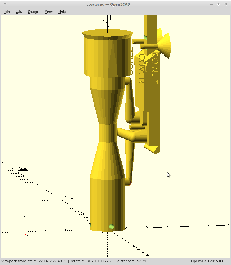
    FInished a venturi version.

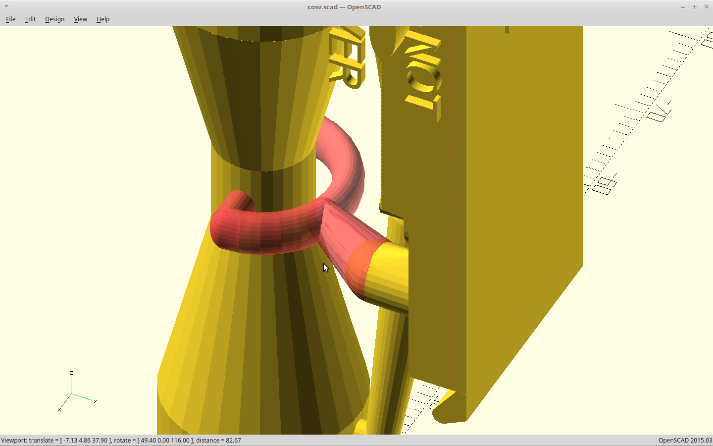
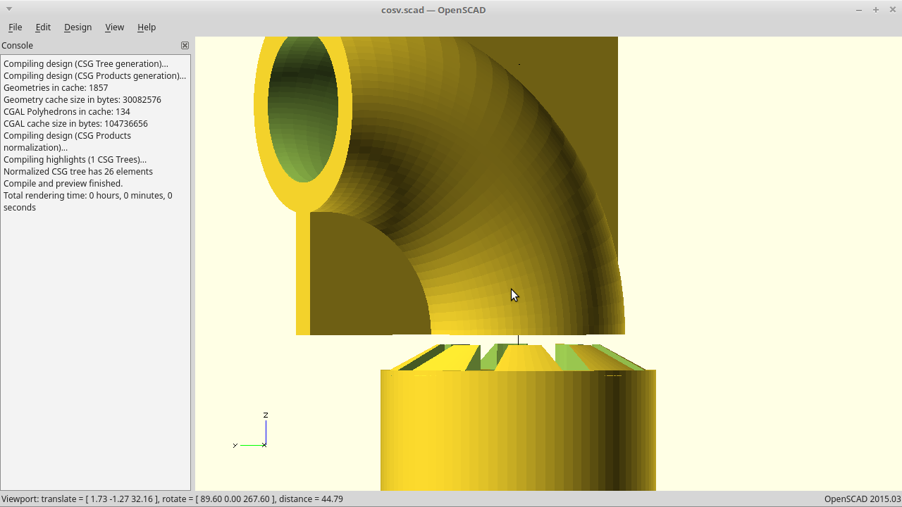
      These are the internal cutouts.

  • Classy

    Daren Schwenke04/26/2020 at 08:33 0 comments

    One huge step away from everything working together..

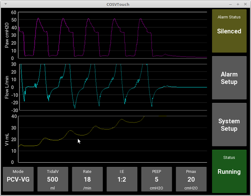
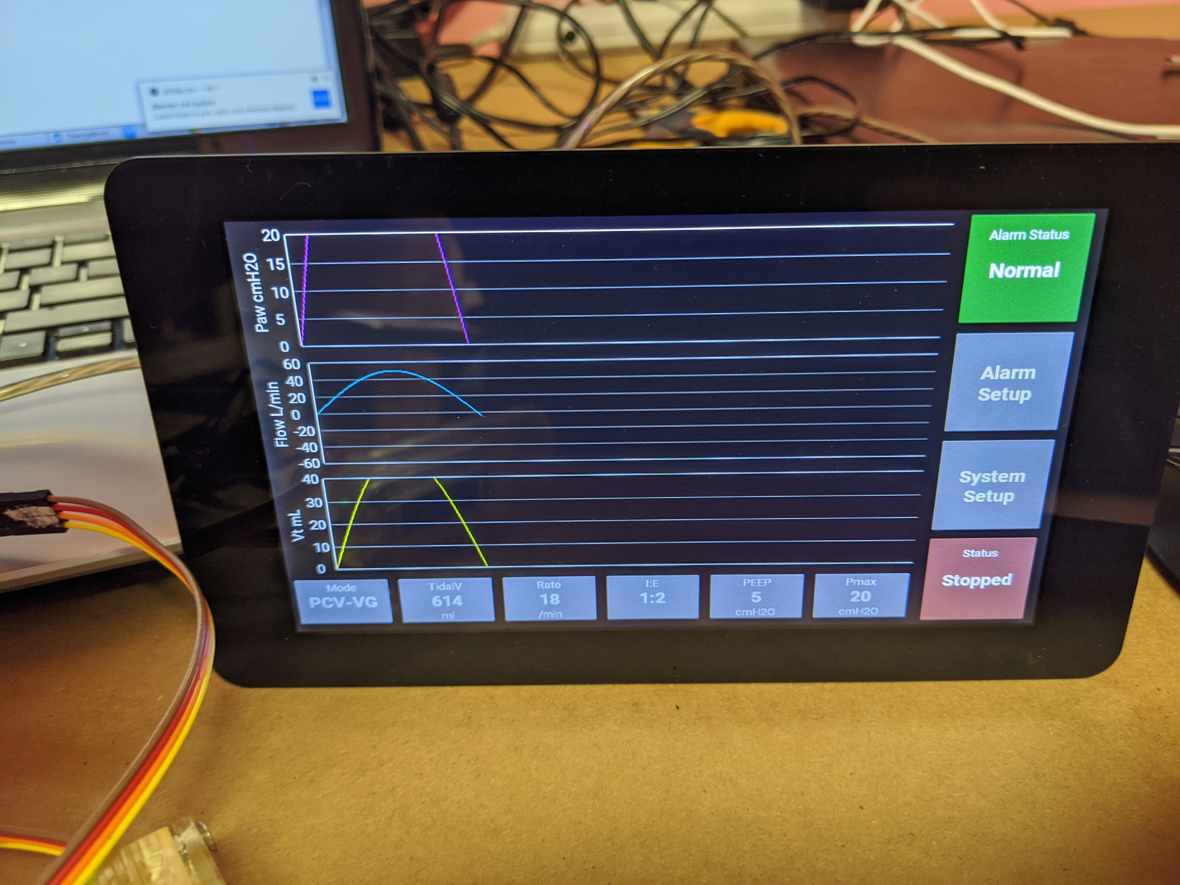
    The UI got a rewrite and is now classy, eventful, private, and modal. The buttons even do things, and the serial logic for chatting with the core is taking shape.  Code is up on Github.  Event triggers on variable changes and proper config files would be nice.  The former is still giving me issues.

  • Clear is pretty and a Venturi effect

    Daren Schwenke04/25/2020 at 16:36 0 comments

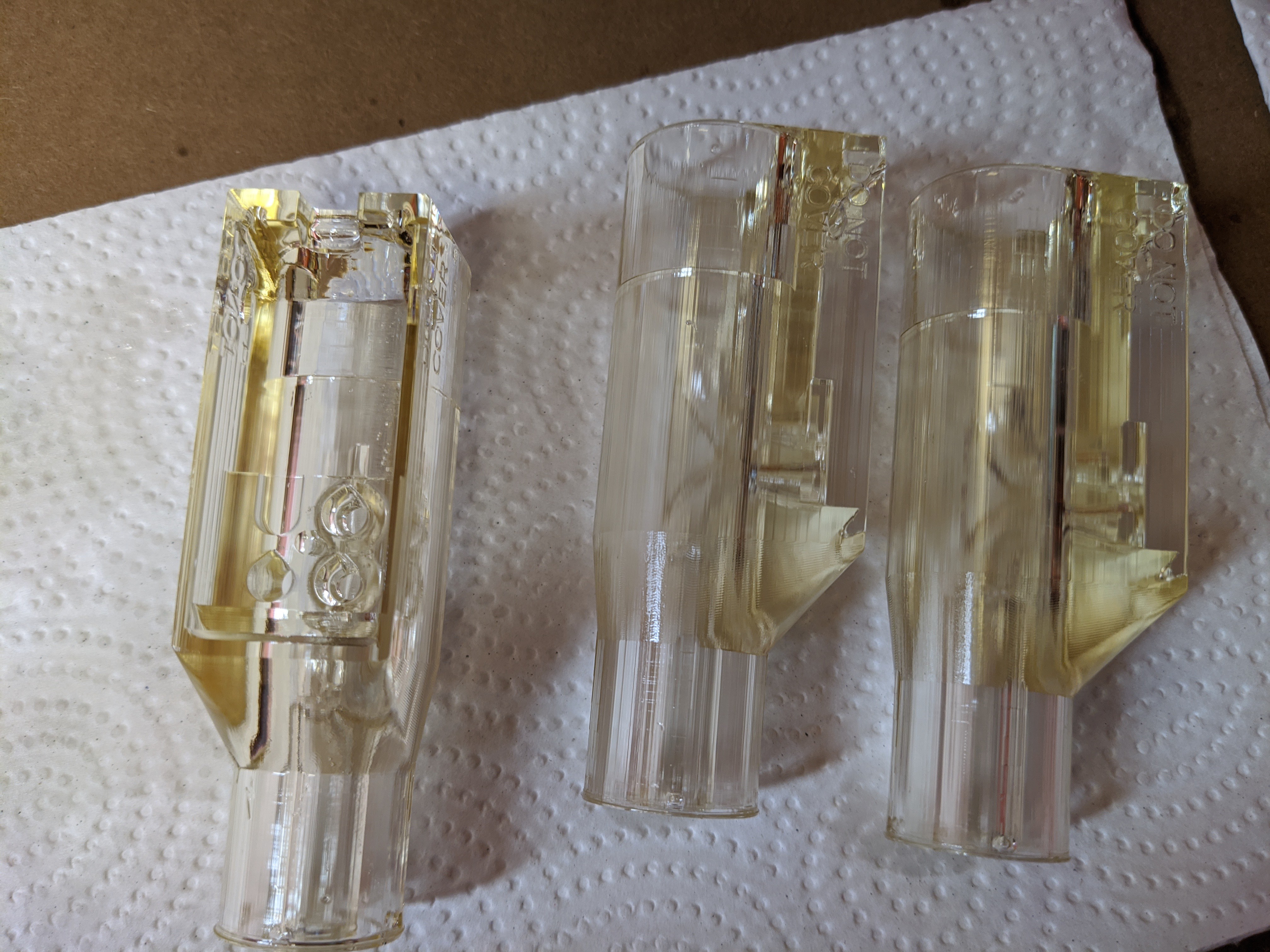
    We printed some pitot pickups in clear.  Oooooo..

    A test on another set shows a significant Venturi effect on our pressure pickup.  I need to move it out of the restriction.  That should be relatively simple.

    The pressure drops during flow almost as much as our pitot tubes are producing.  We should get to graphing this today.  If the effect is significant enough, we may use it.

  • Calibrated flow source

    Daren Schwenke04/11/2020 at 15:17 2 comments

    We need to generate a coefficient for our sensors when attached to out pitot tubes.  To do that we need to have a precise source of airflow.

    The current thought process is leaning towards pvc pipe with a piston in it.  Move the piston down the pipe and your are displacing a known volume of air, which we can send through our sensor and calibrate it.

    Problem is for a 4in pipe and using 5/16in threaded rod (18 tpi) , that rod would need to spin at 8k rpm to move fast enough to hit our upper target for flow.  Move to a 6in pipe, and use 1/2in threaded rod (9 tpi) and that number is a lot more reasonable 2k rpm.  

    Working on it.

  • When you're a Jet

    Daren Schwenke04/10/2020 at 21:38 0 comments

    We had some more copies of the body printed the other day on SLA.

    The snap off bit for the lower pitot still liked to take a bit of the tube with it when printed on low resolution SLA printers.

    I made it a bit weaker and the pitot a bit stronger.

    Also sorted the lower overhang making it a big more gentle, and matched the body width to the new PCB width.

    Files are now rendered and up on Github.

  • Test board partial success

    Daren Schwenke04/10/2020 at 06:37 0 comments

    The boards arrived from OSHPark yesterday and @Steven.Carr  got right to work populating them for reflow.
    He ran into some issues.

    Our placement for the pads to allow either the BMP280/BME280 or BMP388 sensor to live on them was problematic and resulted in failure to properly reflow without the case shorting to one of the adjacent pads/lines.
    They are too close together.

    Steven eventually was able to salvage a few for testing through some careful rework so this is not a total loss though.
    The good news is the xlator is doing its job, and we have two sensors which are working in the right configuration now to move forward.

    This will enable us to test a few different pitot tube configurations to determine the ideal gain/flow tradeoff.  Bigger tubes give us more gain, but this will also increase the restriction through the pickup reducing our overall flow.

    I'll be modeling a range of pitot tube sizes for him to try out.  We will still need some form of calibrated flow to compare these though.  We'll have to work on that.  Worst case a garbage bag full of air would give us a calibrated volume from which we could extrapolate the flow, but that wouldn't give us very much to work with.  We'll need something better.

View all 22 project logs

Enjoy this project?

Share

Discussions

gmeaton wrote 04/22/2020 at 02:53 point

If you do a deep dive into the SFM3300, they use a perforated aperature plate. This is a nice setup as it would help to break up vortices (A.K.A Karman Street) which could present a pressure modulation at your sensor ports and possibly a pertubation in your transfer function. 

  Are you sure? yes | no

Daren Schwenke wrote 04/22/2020 at 04:38 point

Yes!  I did notice the stainless screens myself.  :)  We actually were able to measure that already as when we did our initial tests with a standalone pitot tube, the ports started right on the leading edge.  That resulted in a reading which was skewed downwards and depended on the tube heading into the pickup. 
We have tried to address the inconsistency in the flow by moving the sensing package to the vertical center of the current model, so there it has a built-in lead-in area from both directions.  If this proves to be not enough, I do have a hexagonal print I can drop in both ends that won't require modifying the existing package or starting a print in midair.

There was another suggestion of using a hexagonal print area as our flow restriction for a more targeted orifice type pickup, but the problem with that is every deviation in the printed width of the parts results in multiplying our error.  It gets bad pretty quickly.  So the hexagonal flow alignment parts, if needed, are not going to be part of the sensing area.  That should limit our cumulative error based on imperfect extrusion to a calculated 12%.

  Are you sure? yes | no

Steve Glow wrote 04/13/2020 at 13:24 point

Daren, I've had great success using PCBway for quick turn boards.  They're very inexpensive ($5 for 10 small two layer boards) and typically ship within a day.  Located in China, so the shipping is the slowest and most expensive part.  If I'm in a hurry I select fedex International Priority which typically runs about $30.  That gets me the boards in just 2-3 days.

Good luck with the Pitot tube approach.  I'm busily working on my venturi tube version.

  Are you sure? yes | no

Thomas Stilwell wrote 04/15/2020 at 03:30 point

Does pcbway really ship within a day? That's much faster than elecrow shipping in 4 days which I usually use.

  Are you sure? yes | no

Steve Glow wrote 04/15/2020 at 14:56 point

Yup, for simple two sided boards they normally turn them around in 1-2 days.  Fedex IP is the fastest shipping method in my experience and usually takes about 3 days from China.

  Are you sure? yes | no

Daren Schwenke wrote 04/22/2020 at 04:49 point

Thank you Steve.  We have had less than stellar results with JLCPCB at this point.  Some of our boards had the sensors flipped 180, *within the same order*.  I have yet to document our disappointment here as I'm hoping that they will make it right. 
That was a *huge* waste of time for all involved and resulted in the destruction of 6 of our 10 boards we were going to use for validation/testing.  I'm basically incapable of reworking these tiny components due to nerve damage.. but I sure did try.  That is actually the reason #Arcus-3D-P1 - Pick and Place for 3D printers got started.

The pitot tube is more of a combined orifice/pitot tube approach at this point due to the significant percentage of the tube that the pitot now occupies.  It is looking like it gives us the best of both worlds.  I will admit that a venturi design was on the back burner just in case it didn't work out though, but with the pitot design I get a bit more gain as the leading sensor is under pressure, but the trailing sensor is also under a slight vacuum.

  Are you sure? yes | no

chris wrote 04/06/2020 at 21:17 point

Also, I hate to break it to you but the BMP280 is pressure only.  If you want temp and humidity you need the BME280.  Unfortunately not the same size package close but larger.

  Are you sure? yes | no

Daren Schwenke wrote 04/06/2020 at 22:04 point

Doh.  The difference one letter will make... 
Thank you for pointing this out.  We are actually looking at the Chinese clone of the BMP388 right now and dropping humidity for all the sensors anyway.  

  Are you sure? yes | no

chris wrote 04/06/2020 at 15:41 point

Your sensor tubes are huge compared to the inner diameter of this part.  The tube orifice should be like 1/8 to 1/15 diameter of the inner diameter or they distort the flow too much.  You can streamline the tubes where they enter the wall to minimize the flow distortion.

  Are you sure? yes | no

Daren Schwenke wrote 04/06/2020 at 22:02 point

This is intentional (now).  We will (probably) need higher gain, and making the ports a significant fraction of the tube size gives us some of the gain of an orifice type pickup while still having directional data.

  Are you sure? yes | no

David W wrote 04/06/2020 at 09:50 point

Hi. Very nice project. I'd like to make some of these sensors (with JLCPCB) for prototyping our vent (openvent.org), maybe some small modifications are needed. Can I get in contact? hobodrifterdavid@gmail.com :-)

  Are you sure? yes | no

Daren Schwenke wrote 04/06/2020 at 22:04 point

Replied, worked, met.  Thank you!

  Are you sure? yes | no

flanagan wrote 04/05/2020 at 01:04 point

Thanks. I am driving valves no vfd or stepper.100% valves.. any res is good. Thanks again.

  Are you sure? yes | no

Daren Schwenke wrote 04/07/2020 at 04:04 point

The data from a new test using the BMP180 sensors looks great. Post is above.

  Are you sure? yes | no

flanagan wrote 04/04/2020 at 21:38 point

I have confirmed the control operation on my ventilator, beginning pneumatic assembly on bench prior to interning in cabinet. Looking at instrumentation options , your device appears to have the parameters I would want. How is it going?

This thing is coming together now. So any input is helpful.

Thanks.

  Are you sure? yes | no

Daren Schwenke wrote 04/04/2020 at 21:54 point

The sensitivity may be inadequate using the chosen sensors.  We hope to find out today using the real thing instead of the older generation of them.

  Are you sure? yes | no

flanagan wrote 04/04/2020 at 22:51 point

Thanks, I really only need to set thresholds for signal . I apologize for fielding questions that are likely covered in your material. Thanks for your patience. what is the sensing range for flow and psig operating range?(of your current prototype) 

  Are you sure? yes | no

Daren Schwenke wrote 04/04/2020 at 23:14 point

@flanagan Pressure sensitivity will be fine.  What may be inadequate is the resolution of the flow data from the pitot tube differential.
For the earlier prototype sensor with just tubes we were seeing 1cm of water column difference when I breathed through it.  Based on this and the sensor specifications, we should have had about 1k steps between inhale/exhale.  In reality, this may be turning out to be less. 
Aka... we won't really know until we finish a full prototype.  Everything has been tested in bits.

  Are you sure? yes | no

gr5 wrote 04/04/2020 at 02:38 point

Could you please publish the mechanical design?  I want to see if your design will suit my needs (ventilator) of if I need to change some things.  openSCAD files would be perfect but I'll settle for STL file.  Anything would be helpful.  Thanks.

  Are you sure? yes | no

gr5 wrote 04/04/2020 at 02:49 point

Nevermind.  I found everything on the parent project linked to  near the top of this page.  Both source cad and STL files.  Thanks.

I'm wondering how you knew what to do for the positioning of the pneumatic paths.  Did you more or less copy an existing design?  Or have you done these before?  Is there a guide for making flow sensors using pressure sensors somewhere?  :)

  Are you sure? yes | no

Daren Schwenke wrote 04/04/2020 at 21:52 point

I looked at the existing designs for S type pitot tubes and winged it.  Beyond that testing showed it needed to have a lead-in area.  There are three basic types you can look up yourself.  Pitot tubes, orifice plates, and venturi.  Pitot tubes work by stagnation pressure (air stacking up in them), orifice plates by creating a restriction and reading the pressure before and immediately after, and venturi by a similar method to orifice plates except that your pickup is within the restriction.

  Are you sure? yes | no

Jmayes wrote 04/03/2020 at 13:59 point

I am curious on how you are going to seal the sensors to the tubes, I printed one up and have been wondering about that .  How did your testing go?

  Are you sure? yes | no

Daren Schwenke wrote 04/03/2020 at 22:05 point

A touch of RTV on the sensor mount surface, a single screw in the middle.  The sensors are getting reflowed to the boards, and just sealing the board to the printed bit is enough as they are absolute (no air channel needed to the back of them or such).  There is a keep-out specified in the pcb layout to keep the vias out of the area that needs to be sealed.
No graphics of this as two incompatible systems being used, but we generated the outline and everything fits.

  Are you sure? yes | no

Adam Quantrill wrote 04/01/2020 at 18:47 point

Did you also think about a CO2 sensor  - I picked a few up quite cheap, they are rated up to 10000ppm but I am going to see if they can handle 40000ppm. Could be useful to monitor exhaled CO2, for logging or alarm purposes.

  Are you sure? yes | no

Daren Schwenke wrote 04/01/2020 at 21:56 point

I did not. They are huge compared to what we have right now. The whole board is 40x16mm, and the enclosure /pickups for it are like 40mm more than that total. O2 monitoring would be pretty useful, but those are also not small and power hungry. For now, as long as the air is moving in both directions, we have O2 going in, and CO2 coming out.  If we don't, we have bigger problems that a ventilator is not likely to solve..

  Are you sure? yes | no

Adam Quantrill wrote 04/02/2020 at 00:02 point

The sensors I found are 4mm square approx, and the whole I2S EVB  I bought maybe 20mm square. Not excessive. 

Odd I can't reply below hope you spot this here

https://ams.com/documents/20143/36005/CCS811_DS000459_7-00.pdf/

• 2.7mm x 4.0mm x 1.1mm LGA package

  Are you sure? yes | no

Daren Schwenke wrote 04/02/2020 at 00:23 point

@Adam Quantrill Please share then.  I'm used to the huge ones apparently.  Thank you.  As the design is right now we could accommodate probably one more sensor without going over our 1 square in limit or going to the backside.

  Are you sure? yes | no

Daren Schwenke wrote 04/02/2020 at 23:14 point

@Adam Quantrill Yeah, they limit the depth of conversations.  Just do the @username trick and they still get notified if you reply.  Thank you.  I'll look at that.

  Are you sure? yes | no

flanagan wrote 04/01/2020 at 16:57 point

Is this for point of use monitoring or control?

  Are you sure? yes | no

Daren Schwenke wrote 04/01/2020 at 21:53 point

Both. Our goal is control, but the whole backside of the board is free and the case has a slot for an OLED already. This is step one.

  Are you sure? yes | no

flanagan wrote 04/02/2020 at 12:54 point

So...are you thinking remote HMI and sensor interface coupled to parent control?

How close are you?

  Are you sure? yes | no

Daren Schwenke wrote 04/02/2020 at 15:28 point

@flanagan This is the remote sensor.  It has a slot for an OLED we may put something on.  It was just easy to do so, so we did.  The plan right now is our MCU will live on the vent, but we have discussed making this the brains of the whole device.  Then we could just supply the signals needed to drive the support devices (motor or valves) from here.  Interface is a bit small for this though.  Our whole board is less than a square in.  We would have room for about 4 capsense buttons, not much else, and that display is too small for quick observation from a distance.  So the short term plan is leave this like it is, move on, get it tested and calibrated, and put the MCU on the vent along with basic controls.  The vent will have its own display.  But it is something we plan to come back to.  The boards are being fabricated now and we should have them in a few days.

  Are you sure? yes | no

Jmayes wrote 03/31/2020 at 02:18 point

Are the PCB files avl?  Also is there any example driver code for reading the sensor?  This is exactly what we have been looking for in our DIY Ventilator.  J

  Are you sure? yes | no

Daren Schwenke wrote 03/31/2020 at 03:26 point

@Jeff Mayes @djeddleman The board just came together today.  Yes, we will be releasing the files, but we would love to actually test one first before someone goes spinning up 1000 of them  :)  If you want to help with that, PM me or @Steven.Carr 

  Are you sure? yes | no

Jmayes wrote 03/31/2020 at 12:39 point

Oh, I did not realize you were still in progress, by all means test, test, test, test!  I will work on printing one up today to be ready for the rest.  Great work!  TX

  Are you sure? yes | no

djeddleman wrote 03/31/2020 at 16:11 point

I have an LTC4316 demo board and two BMP180 boards (similar to the BMP280's) on hand. If you have trouble with the board testing, feel free to let me know.

I notice that you used the 24C01ASM as the EEPROM on your PCB. Make sure you use a 3.3V compatible version of the EEPROM, as the original 24C01ASM is intended for 5V operation.

  Are you sure? yes | no

Daren Schwenke wrote 03/31/2020 at 17:31 point

@Jmayes This project is a whopping three days old.  We are still iterating, sometimes several times a day, and everything you see and can download is still actively in flux.

  Are you sure? yes | no

Daren Schwenke wrote 03/31/2020 at 17:36 point

@djeddleman Thanks!  That would tell us if our design electrically works at least and could help us get a head start on writing a driver.  If you used one of the older pitot tube designs (not an all in one like this) and some kind of cover we could test the basic flow sensing idea using your development boards.  Thus far we have just done water column measurements to make sure we were in the right range. PM me.
Good to note about the eeprom.

  Are you sure? yes | no

djeddleman wrote 03/30/2020 at 17:58 point

Are the Eagle schematic/layout files available? (*.brd/*.sch) I can help review them, and it's easiest to do it directly in Eagle.

  Are you sure? yes | no

Rob wrote 03/29/2020 at 20:36 point

What happened to the MPXV7002DP ? At first glance seems like that, with a BME280 or 2 would be a better / easier solution?

  Are you sure? yes | no

Daren Schwenke wrote 03/29/2020 at 20:48 point

it got eliminated.  This works via I2C so I don't need to extend the analog signals from the MPX back to the MCU and is half the cost/higher resolution.  The MCU ADC resolution is 12 bit, whereas I get 24 bit resolution from the barometric sensor.  Granted I'm using less of the range to do it so it probably all evens out.

  Are you sure? yes | no

Rob wrote 03/29/2020 at 21:42 point

Fair enough, but I'm worried about drift / relative calibration errors between the units. My spidey sense tells me having 2 (or 4 in this case) independent sensors that you are then doing software tricks for sensor fusion, could be an issue. Especially in mass production? Just thinking about if one gets a little warm, or wet, or contaminated etc, would be hard to tell from a software point of view.

Sorry for playing devils advocate but we're working on our own design at the moment and I was looking at the same differential pressure sensor as a basis (the analogue interfacing and slightly higher cost doesn't phase me, especially in light of potentially more reliable design).
Actually printing out your NEMA23 based design at the moment to give it a try :)

  Are you sure? yes | no

Daren Schwenke wrote 03/30/2020 at 05:44 point

@Rob That is why we have an onboard eeprom in the schematic.  Not sure we are going to need it but if the calibration really differs by that much, we already have somewhere to store those numbers that is permanently tied to the unit.  We also have a couple different comparisons we can do to idiot check the numbers.  Also, the BMP388 actually lists testing lung function as one of its applications.  :)

Good luck on the stepper and let me know how it goes.  BTW variable volume will be controlled by turning 1/4 turn, and then returning back to start. For testing you can just spin it though for full volume.

We got some new numbers from the UK document and at the rates they want the inhale to occur, I'm not sure my motor selection will hack it anymore.  

The old number was 1.5s, and so I targeted 1.0s for some headroom.  

The new number is 0.3s!  That is 3x faster than I had specified and 5x faster than the original spec.  Come on...

If it takes 3x the force, the Nema23 is not going to cut it.  The BLDC I originally specified is also probably doomed.

You'll probably get it turning before I do at this rate, so let me know!

  Are you sure? yes | no

Similar Projects

Does this project spark your interest?

Become a member to follow this project and never miss any updates