 Stephen Holdaway
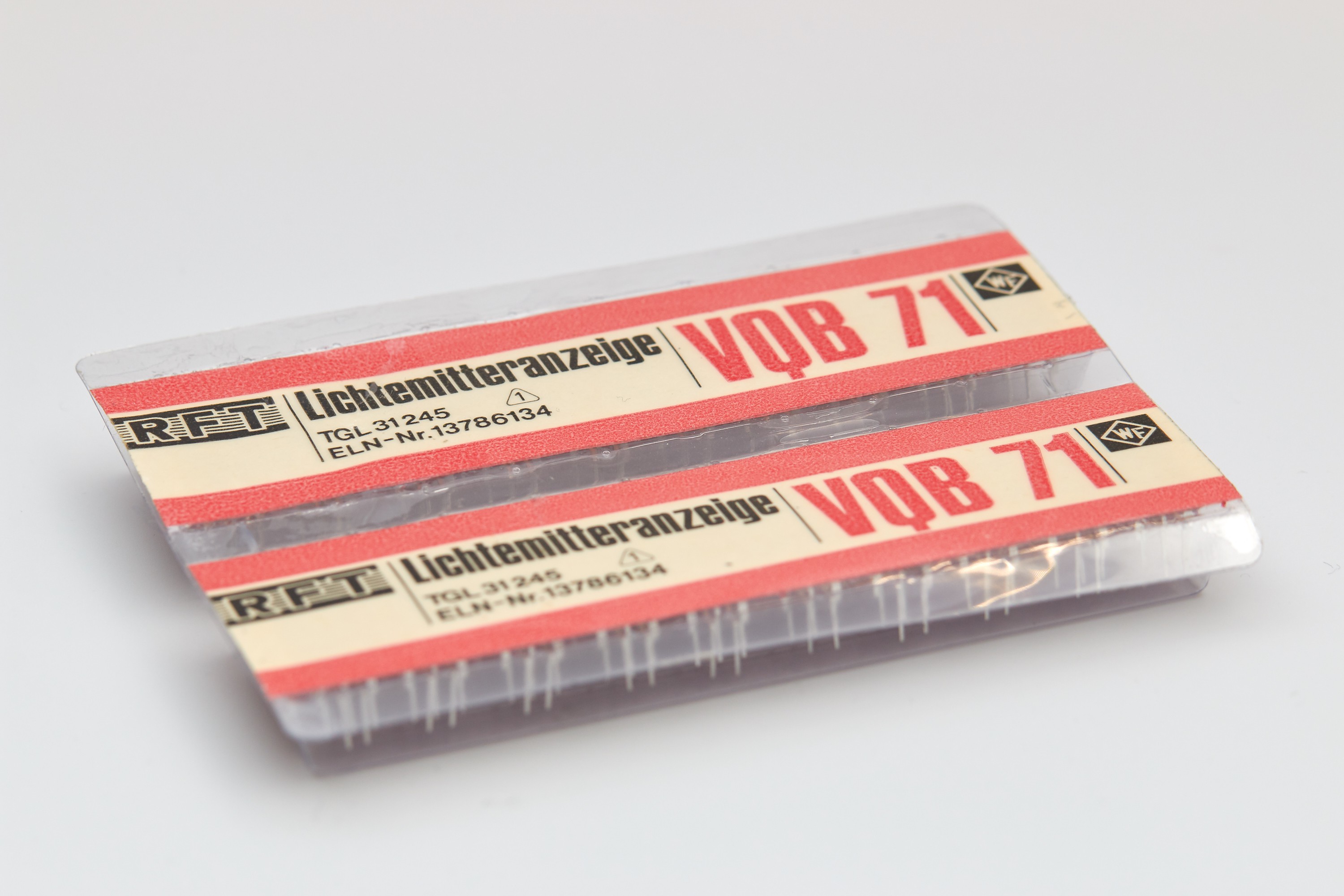
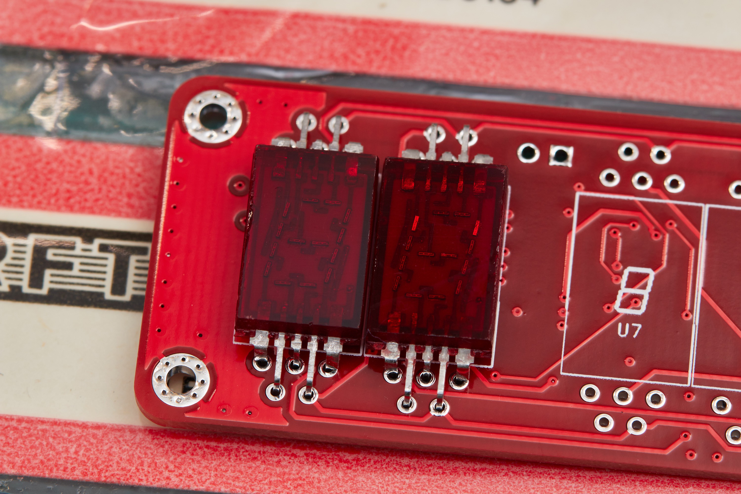
A year ago I picked up some new-old-stock "VQB 71" 7-segment displays — not for any particular project, but simply because they looked fantastic. These gorgeous, vintage common-anode digits have distinctive segments with six tiny LEDs each, internally connected with bond-wires and encapsulated in transparent red epoxy/resin:

This batch was manufactured in 1989* by WF Berlin (Werk für Fernsehelektronik), a division of the East German state-owned company VEB Kombinat Mikroelektronik Erfurt. The packaging is titled "lichtemitteranzeige" which is literally "light emitting display": an odd name by modern standards according to a German colleague of mine, who said this would simply be labelled "sieben segmentanzeige" today.

A few partial scans of datasheets for the VQB 71 are available online, with the one below from tu-chemnitz.de being the most complete copy I've found. A datasheet isn't strictly necessary here, but it's useful to have dimensions provided for the footprint, and I wanted to know the maximum current per segment specified by the manufacturer. After all, These parts haven't been made for nearly 30 years, so it would be a shame to destroy one accidentally.

It's easy enough to figure out the specs without knowing any German, but Google Translate makes quick work of the dry/technical language. Here's the English translation of this datasheet:
VQB 71
Not for new designs
Light emitting display made of red-beam GaAsP diodes in a segment design to display the digits 0...9 and a decimal point (DP). The wavelength of their max emission is 630...690 nm. The half width is 40 nm.
Limits Forward direct current / segment or DP at θa -25...25 °C IF max 15 mA DC blocking voltage at θa -25...+70 °C UR max 4 V Operating temperature θa -25...+70 °C Storage temperature for storage up to 30 days θstg -50...+70 °C
Characteristic values at θa = 25°C Luminous intensity / segment at IF = 10 mA IV typ 150 μcd ↳ Decimal point IV typ 100 μcd Forward DC voltage / segment at IF = 10 mA UF max 3.6 V ↳ Decimal point UF max 1.8 V
Note that unlike modern LED datasheets, this doesn't specify maximum pulsed currents. Pulsed currents with modern LEDs are typically 3-5x the max constant current rating (dependent on duty cycle and pulse duration), which can give some head-room for driving them harder in multiplexed configurations.
Driving these segments with a constant 10mA as the datasheet suggests gives a high-contrast image in vivid red. The VQB 71's are so intensely red that it's proved difficult to capture an accurate representation of one on camera. Modern LEDs like those in the GPS Wall Clock look almost orange by comparison.


Driving all segments at this power increases the surface temperature of the digit by around 10°C, but who needs efficiency when you have style, right?
I hear we're building another clock
There are only so many applications for a 7-segment display these days, and I'm a firm believer that one person can never have enough clocks. A miniature version of the GPS Wall Clock for a desk seemed like a nice way to put these vintage digits on display.
This time around there are a few changes:
Bigger processor
It was fun squeezing the original implementation into 1KB of code space on an intentionally small part. This time I'm more interested in expanding functionality: better display accuracy, configuration of the GPS module, more buttons, less pin-sharing, etc. Initially I'd picked the ATMega88PA as I already have a tray of them, but after a first pass on the schematic it was obvious most of the pins would go to waste. I traded it for the physically smaller but otherwise comparable 8-bit STM8S003F3P6.
Due to a shipping error a few years ago, I have more than 100 of these STM8S chips, so they're an easy choice. While not necessarily a popular chip, these are half the price of similar AVR chips new, can be programmed with the dirt-cheap STLinkV2 dongles available from the usual suspects using a SWIM interface, and can be used with an open-source toolchain. The downside is that it's just you and the reference manual when things aren't working, but hey, I enjoy that challenge.

GPS module on-board
Like the original, a GPS receiver will provide time information *from space*, but this time the GPS module will be integrated into the layout instead of wiring up a separate breakout board. New GPS modules from distributors start at about $15 NZD each, so I went the cheap way and grabbed some grey-market u-blox NEO-6M modules for about $5 NZD each. The units I received appear to be leftovers from a production run that have been sitting in a factory for years collecting dust, but they do work correctly.

Improved accuracy
The GPS module has a TIMEPULSE pin that generates a rising edge at the top of each second by default. I was aware of this in the original project, but didn't have any spare pins or program space to handle it. The original build updates its display each time a NMEA RMC ("Recommended Minimum") sentence is received over UART, which works fine, but does make the clock run almost a tenth of a second slow:

This is already accurate enough for practical human purposes, but we can go deeper. Offsets can be configured in the GPS module to account for electrical and processing delays, so in theory it's possible to have nanosecond accuracy. Since this is only keeping time for humans, I'd be very happy with ±1ms accuracy.
Schematic and layout

Only a few things of note here:
- The MAX7219/MAX7221 is designed for common-cathode segment displays, but the VQB 71 is common-anode. Wiring the display "backwards" with segments to digit pins and digits to segment pins allows this to work. The trade-off is needing extra software to handle the memory layout being oriented around segments instead of digits:


- The NEO-6M uses the active antenna configuration from u-blox's Hardware Integration Manual. The module technically doesn't need anything else to function, but I've attached the backup battery to avoid cold starts when briefly removing power, since those are painfully slow and require good reception. This is intended to be powered 24/7, so there's no need for an external flash/eeprom.
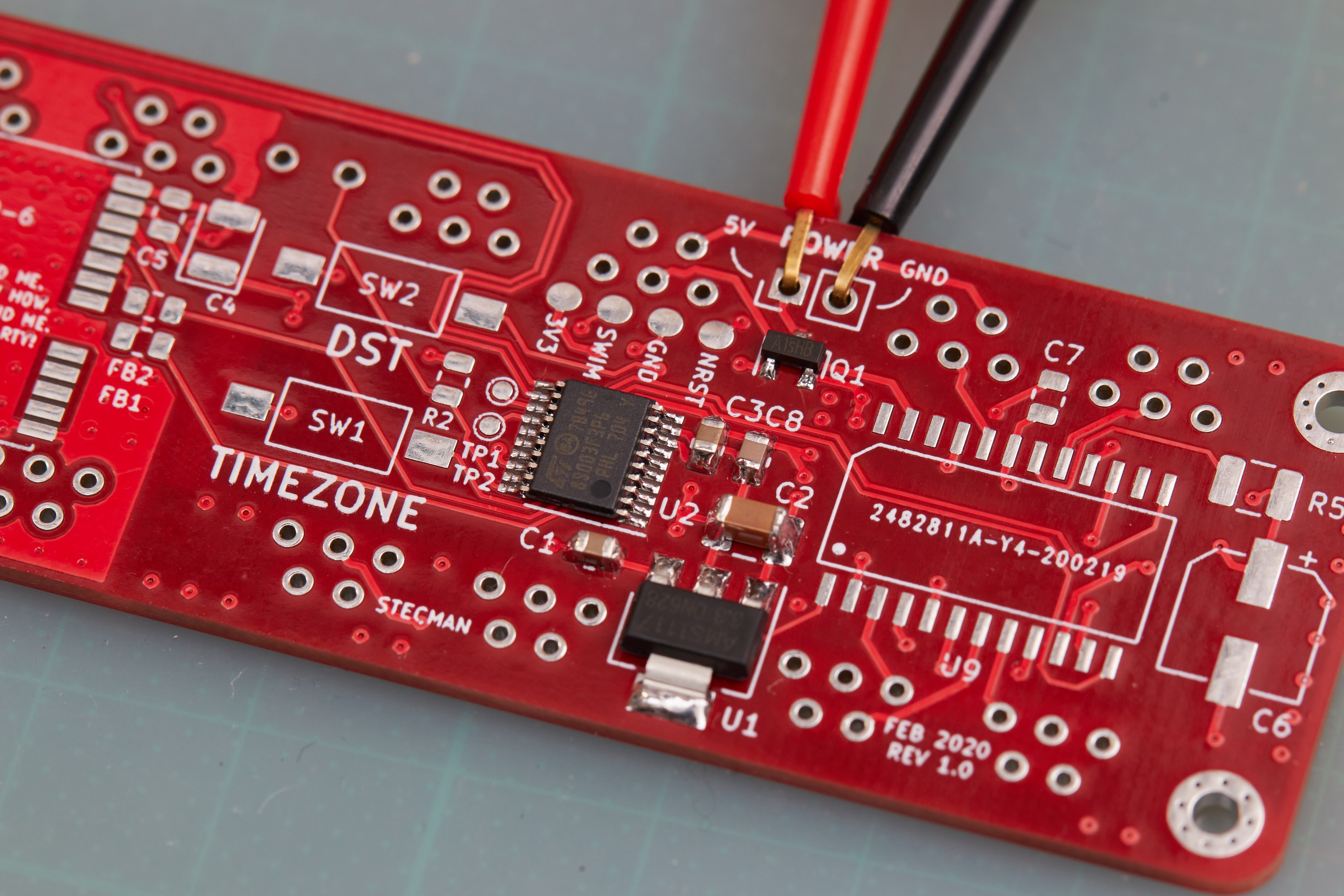
- The power input is 5V with simple polarity protection, regulated to 3.3V for the GPS module and the STM8. This will probably be wired to USB once it's in a case.
- Similar interrupt sources are grouped by port to make interrupt handling simpler. The STM8S lacks dedicated pin-specific interrupts like AVRs tend to have (INT0, INT1, etc) and instead has a shared interrupt per port for pin changes.
This project started as a two-layer board just big enough for six VQB 71 digits, but it quickly became apparent that I was either going to need to make the board larger or go to four layers. I went with the latter as it wasn't prohibitively expensive to jump from two to four layers. It's possible this could've been routed with two layers, but I suspect it would've been quite time consuming. Space around the GPS module is particularly tight, but almost everything I wanted fit:

I'd originally tried to fit a CR2032 battery holder into the layout, but that was taking up 30% of the back and was cut in the end. To save space, the battery is exposed as a header and will reside in the eventual enclosure. The top layer is likely going to double as a front-panel, so I avoided using the space for general layout.
While the circuit is relatively straight forward and uses parts I've worked with before, the GPS module was something I wanted to be extra careful with. I've done zero RF work before, but the NEO-6M's hardware integration manual provides plenty of guidance around antenna layout. This manual in combination with study of existing NEO-6M breakout boards gave me a small amount of confidence that this wouldn't be a reception disaster. The digit pins being so close to the GPS module is an unknown, but there's not a lot that can be done without making the board a few centimetres longer (something I played with early on, but didn't like the look of).
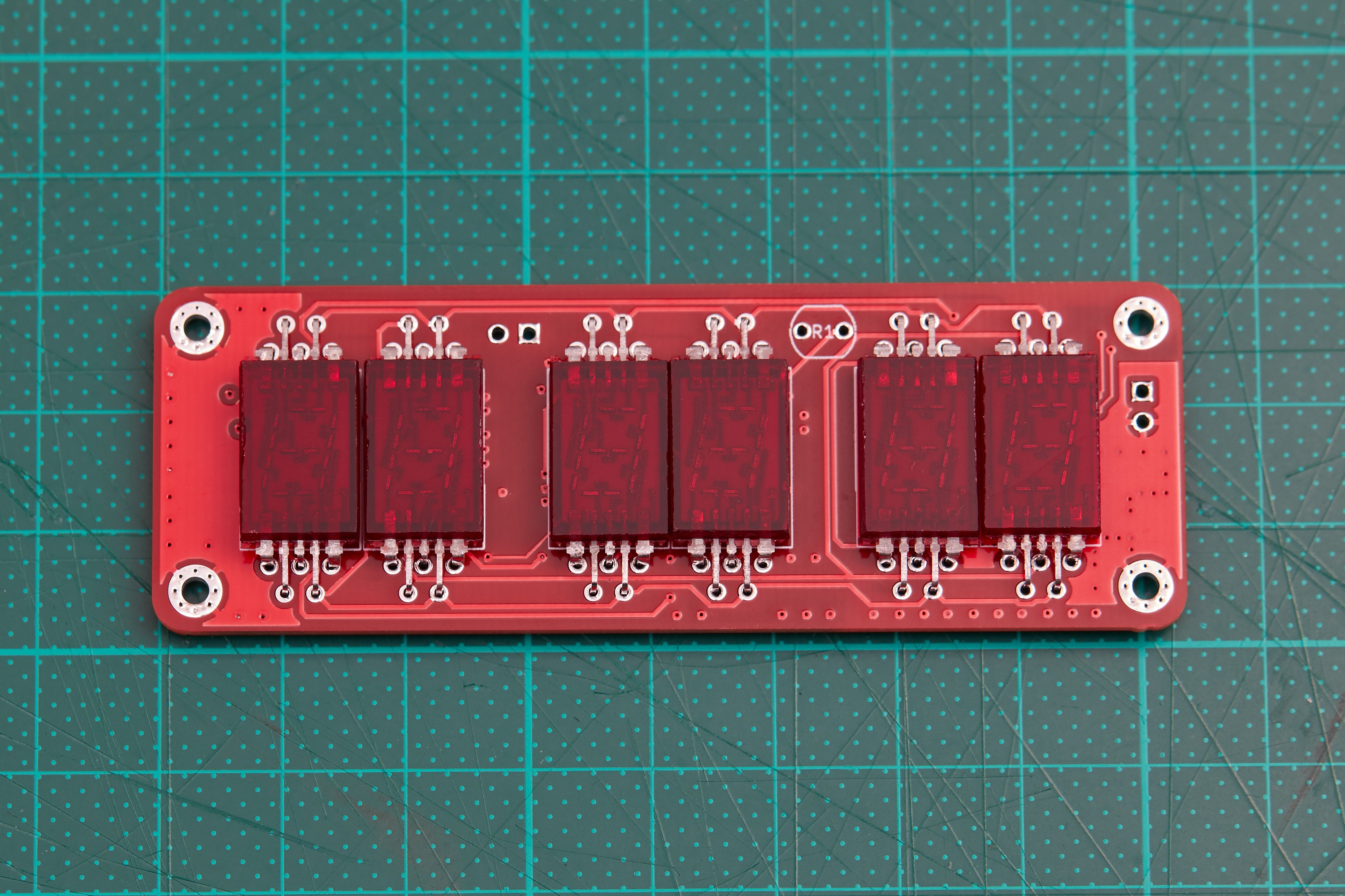
The board went to fab mid-February, was manufactured over the course of 10 days, and took a further 10 days to get to my bench in New Zealand. I went with red solder mask to match the digit casings. It's still hard to beat fresh, shiny new PCBs:

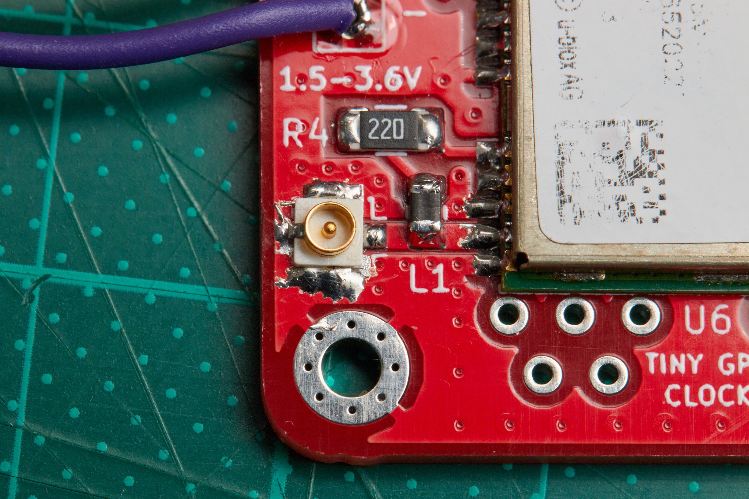
Assembly in pictures
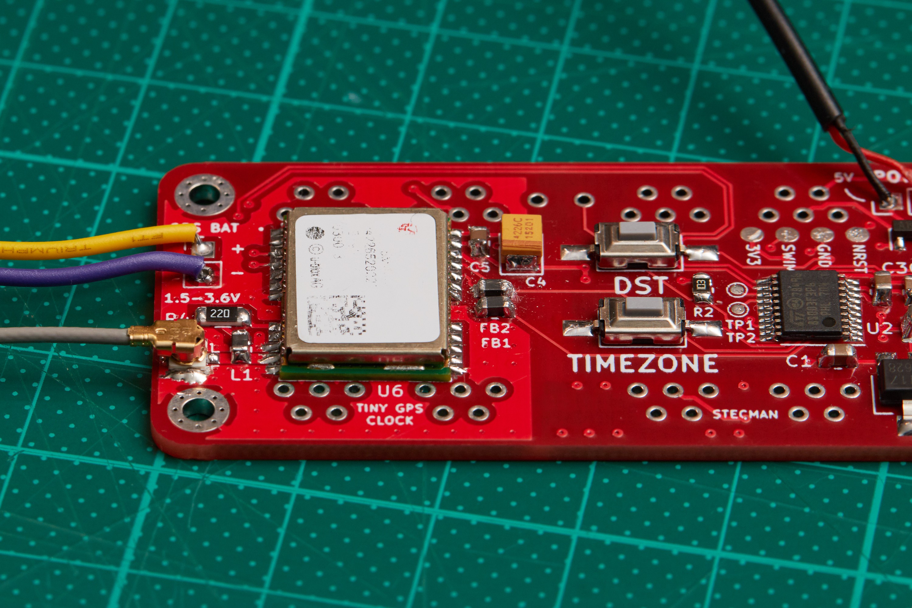

Firmware
To get the clock up and running quickly, I ported the code from the original AVR project to run on the STM8. This only required swapping out a few registers and pin mappings, replacing the SPI, UART and ADC implementations, and adding mapping to set BCD values on the common-anode wiring of the MAX72XX.
When I went to display actual data on the display and turned off the driver's test pattern, I discovered I'd wired the digits in the order {0, 4, 3, 1, 5, 2} instead of the expected {0, 1, 2, 3, 4, 5}. I'd tested with a MAX7219 to find the correct output for digit 0, but I either didn't test the other digits or the MAX7221 has a different output order to the MAX7219. This was a simple fix in software anyway, adding to the existing mapping code.
I'll work more on the firmware over the next few weeks, but for now there's a working clock:


Discussions
Become a Hackaday.io Member
Create an account to leave a comment. Already have an account? Log In.
Very nice post also! Nice little clock! Is this project for sale? Where might I send to order a board or a kit? I have a bunch of the LED's for such a project. If not a kit can the kicad file be converted to Eagle so I may get a board made?
Are you sure? yes | no
What an awesome post! Thanks for going into so much detail and even translating the datasheet for the non Germans :)
Myself being German, I guess not using "Siebensegmentanzeige" (seven segment display) instead of "Lichtemmiteranzeige" (light emmiting display) was because LE(D) was quite new tech at that time plus the German love for "special" sounding and long words.
Looking at the VQB26 datasheet, they call those not "Siebensegmentanzeigen" either but "Lichtschachtbauelemente", which literally translates to "light well components/parts", which doesn't sound much better, right?
Again, thanks for posting! a LOVELY display/clock!
Edit: they're still in (new old) stock here for 2€/pc: https://www.mos-electronic-shop.de/segmentanzeige-p-483.html
Are you sure? yes | no