-
A signal plan
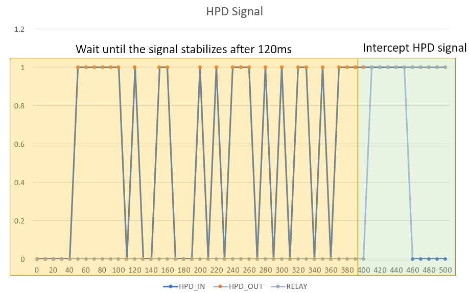
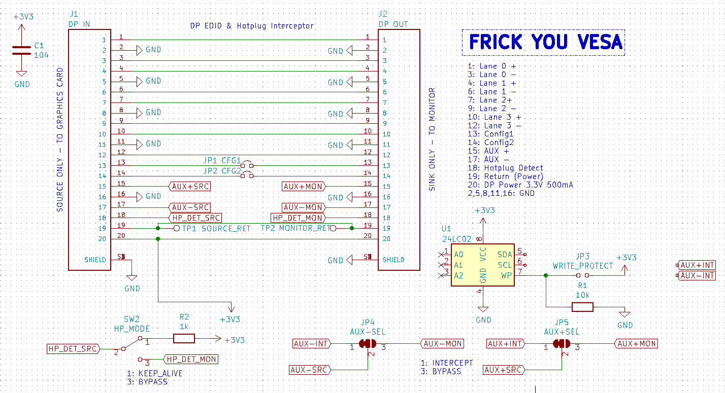
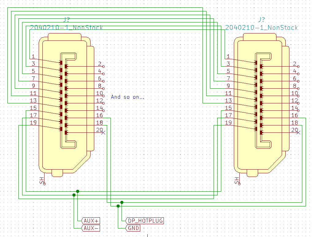
02/19/2023 at 14:28 • 0 commentsThis will be a test setup made with some discarded graphics cards and extenders. We first let the signal through without interruption for 150ms to facilitate communication for the monitor and GPU, which tells the computer what it is and how it should interact with certain aspects of the hardware.
Then, we wait until the signal stabilizes. The moment the HPD signal from the monitor goes down (which would be 3.3V > x > 2.7V), the device intercepts this signal and replaces it with its own 3.3V logic signal (with a 5mA current limit)
When the signal comes back, it immediately hands it back to the monitor (this may change -- may require the AUX lines to be held high at the same time to suppress double communication)
![The planned HPD signal interception The planned HPD signal interception]()
-
Closer look at the "solution"
02/05/2023 at 13:54 • 1 commentWell, looks like I will either have to pony up close to 300 dollars in total in order to get this device, or I will have to make something that emulates what it does. Since I'm still broke, I will choose the latter option for now.
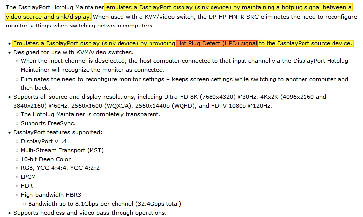
So, let's begin by reading how it works. This comes from this site -- https://www.networktechinc.com/displayport-hotplug-maintainer.html
![]()
It both says "maintaining" and "providing", meaning it can do both (duh). Moreover, it mentions that it also supports headless and passthrough modes, which means it probably doesn't even touch the display signal lines.
Another product exists from Japan that deals with this issue, this time with UART control: https://paleblew.blogspot.com/p/engdphpdma.html
We can also gather information from application notes from Intel and Analog Devices.
![]()
![]()
We now know for sure that this is a 3.3V logic signal. What about the data? It doesn't look like it is transporting much:
![]()
![]()
![]()
We now know that the HPD signal is default high, with interrupt and other one-way signaling done by pulling the line low.
This almost confirms that, should the circuit be made to keep the line high BUT lets the signal (if any) through when it happens, this imaginary circuit will probably work to kill this "feature" until it's unplugged.
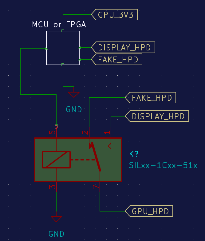
![]()
And the way it works would be something like this:
- First, it lets the signal through without any modification when plugged in for at least 500ms, to ensure whatever transaction occurs between the display and the GPU will succeed
- After that time delay, it waits until the display has stopped giving the "HPD high" signal
- It then immediately intercepts the signal and replaces it with a fake one to continue the signal
- When a button is pressed or some other "stop tampering with the signal please" command is given, it hands the signal over from the fake HPD signal stream (if there's any, to begin with) to the actual signal from the display
- Well, that would be it!
Also, I have a word about VESA; They put this awful text under EVERY page of the documentation as if they're going to sue a customer tired of their antics for copyright violation.
![]()
Suck it, VESA. You made a faulty standard that you're not willing to fix, so I will do it. Don't get in my way because I am very frustrated, and I will not stop until you do something or I conquer your damned standard "feature".
-
Long-awaited "solution"
02/05/2023 at 06:32 • 0 commentsApparently, there is a product called "DisplayPort Hotplug Maintainer" made by NTI, and used by KVM switch setups to prevent the OS from killing the connection and rendering the KVM device useless. It goes for anywhere between 100 and 240 dollars from what I can gather.
It is potentially criminally expensive if all it contains is one chip or one board with a resistor on it, and I plan to get one and see what I can do with it. I'm SO sick of this hotplug issue, and I want to solve it. Please wait until I acquire one and analyze it. Thank you so much for your interest, it is a little relief that I'm not the only one having this issue.
-
The magic is apparently...
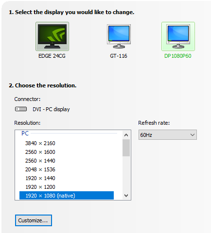
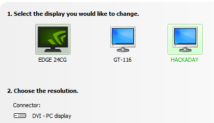
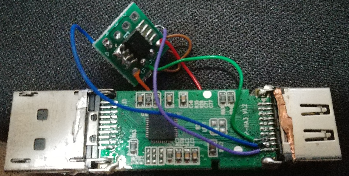
04/28/2021 at 05:57 • 0 comments...Just a regular EEPROM? This dongle is detected as "DVI" (same as the HDMI monitor I have).
![]()
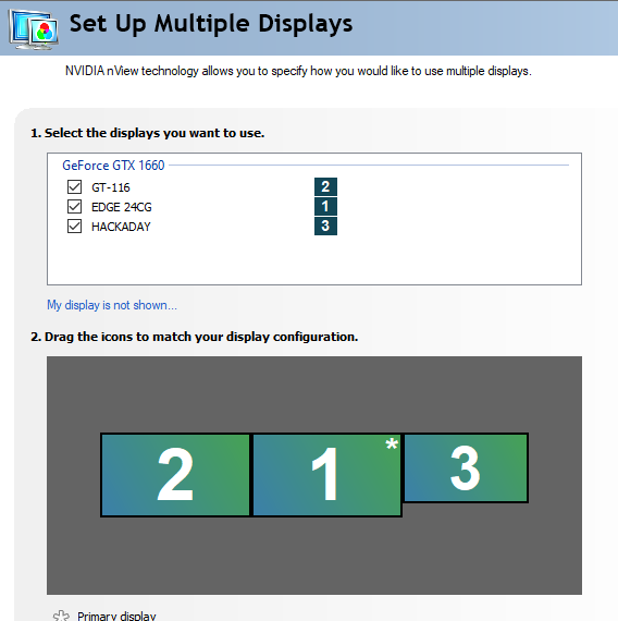
I also discovered that most if not all DP-to-HDMI plugs are also detected as "DVI". I tested 3, and all three are detected as DVI. Even my hacked dongle does that.
![]()
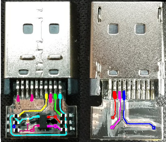
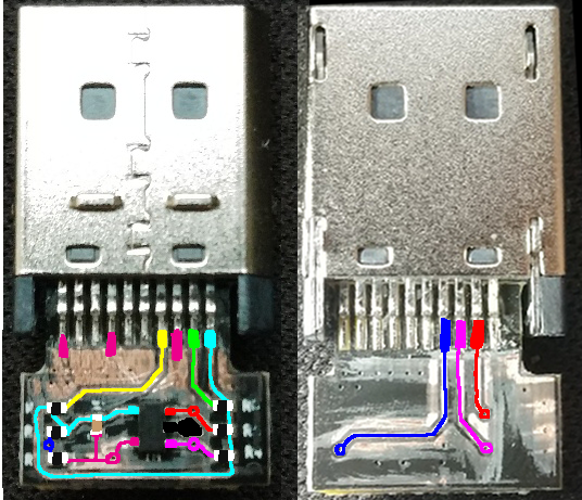
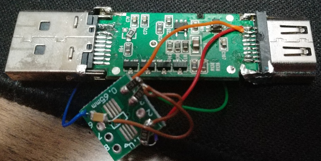
Below are the images of the dongle, with the black solder resist scraped off for visibility.
![]()
![]()
(Image flipped to make reverse-engineering easier)
According to my multimeter, magenta (not pink) is connected to the black pin (middle pin of the three-in-a-row side of the chip).
![]()
Pin 1: Main Link Lane 0 + (Shorted to ground, magenta)
Pin 6: Main Link Lane 1 - (Shorted to ground)
Pin 12: Main Link Lane 3 - (Shorted to ground)
Pin 13: CFG1 (yellow)
Pin 14: CFG2 (blue)
Pin 17: AUX - (green)
Pin 18: Hotplug Detect (red)
Pin 19: Return (cyan)
This is a problem because if the card is thinking this is a DVI or HDMI plug, that also means it cannot be used to manipulate DisplayPort. This is probably a dead end. Very disappointing.
However... Remember the weird behavior with the logic analyzer? I discovered that by simply supplying 3.3V to the HPD pin, the graphics card thinks it is still connected to the monitor, as long as there WAS valid EDID information supplied before it shut off. Maybe it's time to pursue this road?
-
Could this work?
04/13/2021 at 06:35 • 0 commentsI recovered the project file from my drive and made some changes to it.
![]()
The question is, which wire goes where? I won't know for sure until the dummy plug arrives, but the AUX line is definitely used for this purpose. I even created an EDID data for this purpose (that contains a special string so I know for sure it is the right one)00 FF FF FF FF FF FF 00 20 24 37 13 39 05 00 00 17 1F 01 04 A5 34 1E 78 3B DC F1 A6 55 51 9D 26 0E 50 54 AF CF 00 81 C0 81 40 81 80 81 00 95 00 A9 40 B3 00 A9 C0 FE 5B 80 A0 70 38 35 40 30 20 35 00 09 25 21 00 00 1E FB 7E 80 88 70 38 12 40 18 20 35 00 09 25 21 00 00 1E 00 00 00 FD 00 64 90 B4 B4 21 01 0A 20 20 20 20 20 20 00 00 00 FC 00 48 41 43 4B 41 44 41 59 0A 20 20 20 20 01 4C 00 00 00 00 00 00 00 00 00 00 00 00 00 00 00 00 00 00 00 00 00 00 00 00 00 00 00 00 00 00 00 00 00 00 00 00 00 00 00 00 00 00 00 00 00 00 00 00 00 00 00 00 00 00 00 00 00 00 00 00 00 00 00 00 00 00 00 00 00 00 00 00 00 00 00 00 00 00 00 00 00 00 00 00 00 00 00 00 00 00 00 00 00 00 00 00 00 00 00 00 00 00 00 00 00 00 00 00 00 00 00 00 00 00 00 00 00 00 00 00 00 00 00 00 00 00 00 00
Here's hoping that the plug doesn't get stuck in the shipping process because I want this to be solved as soon as possible.
Current plan:
- Acquire a DP dummy plug
- Take it apart
- Copy its EDID supplicant circuit
- Write something to extract info from the registry (if desired, Linux users will have this easy)
- Make sure the chip can be reprogrammed
- Open-source the entire thing
Update: Attaching the EEPROM directly to the AUX line does not work. I'd be pretty shocked if I find out that the plug, which costs $4, is just a DisplayPort-to-HDMI plug permanently wired to a regular HDMI dummy plug. Hoo boy, if that's the case I'll have a gosh-darned field month reverse-engineering the thing... Let me check if it's possible to acquire the chips used in those dongles just in case.
So far the solution seems to be:
![]()
What will fit into the "Some Magical Component" remains to be seen...
But I did get a partial success:
![]()
![]()
![]()
I'm just hoping that this is NOT how those dummy display plugs work, else I'm screwed.
But for now, [Telstra Music-on-Hold - Whistling]
-
Experiment 1
04/12/2021 at 18:45 • 0 commentsAfter hacking up a DisplayPort cable to bits and wiring up headers, I discovered that in most cases the EDID stream is not used (or I suck at triggering it)
I did discover that whenever the display is on, the HPD pin is at 3.3V.
Here's the logic analyzer screenshot (if you can call this "logic")
![]()
Edit: Looks like this cable only has CONFIG wires broken out. I need to investigate further.
Edit 2: Well, no dice. Still no stream.
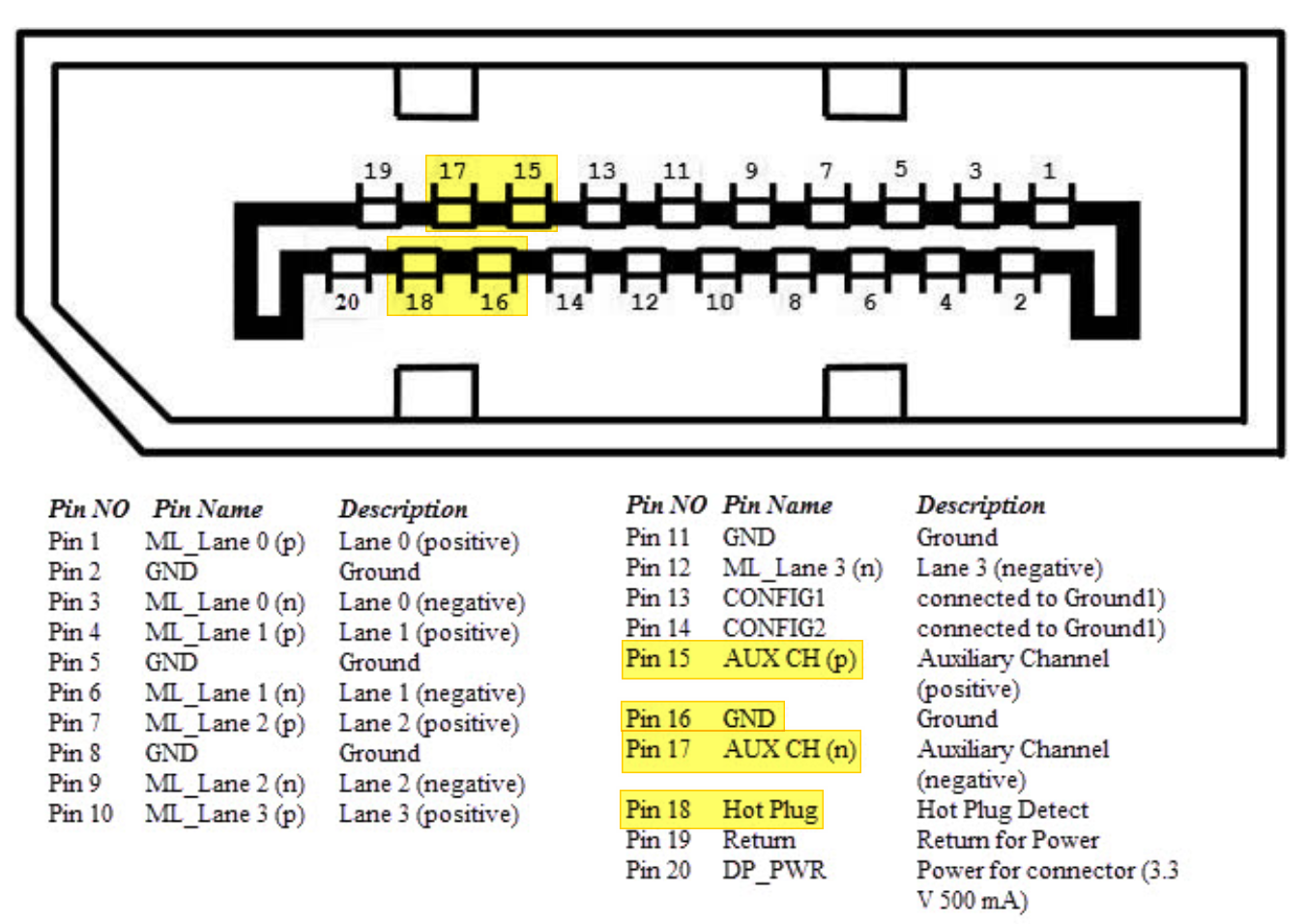
I'm tapping into these pins:![]()
So far, I only saw the Hot Plug pin going high and low when it's switched on and off, and I was unable to capture anything on Pin 15 and 17.
The wiring looks like this (Basically everything is a passthrough, and I'm tapping off of those 4 wires, and there are 1.5K resistors in series so I don't accidentally fry the card should the probe touch the ground and the pin at the same time)
![]()
One interesting observation is that if I connect the logic analyzer (a cheap Saleae USB logic analyzer clone), the computer thinks there's still a display connected, even if the cable is disconnected. So if all fails, I could simply tap off of unused Pin 20 for 3.3V, insert a resistor between that and Pin 18, and pass everything through...
(Also sorry for all the little updates flooding the feed, I forgot to uncheck the little checkbox that does the stuff) -
Cursory research
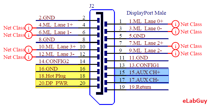
04/12/2021 at 11:03 • 0 comments![]()
We're interested in those three (or 5) pins highlighted: GND, DP_PWR, and Hot Plug. (AUX CH+ and CH- is for DDC, and we want that for the EDID)
We could just forget about the DDC EDID, but this may cause some problems if the host device attempts to read the EDID when the display is turned off or the Hot Plug pin is used to initiate a specific function on AUX pins. Some devices also use DDC to control the parameters of the display, which means it gets very very tedious to manage all of that.
I think there are few options on this one:
- Completely ignore the DDC channel, only intercept Hot Plug signal (breaks USB-over-DP and possibly more features)
- Intercept both HPD and AUX pins, force the computer to think there's a display attached (easiest, but obviously breaks some features unless other data streams are passed through)
- Attempt to intercept only EDID and HPD, let the source and sink device data through (hardest)
Come to think of it, I might be (50% sure I am) making a mountain out of a molehill; Probably most computer monitors only use the DDC channel exclusively for EDID (so the OS remembers the monitor) and HPD pin, and doesn't utilize other functions, especially on the lower-end, consumer devices. Moreover, VESA specifications only say (paraphrasing) "AUX lines also can carry other data, such as USB" but doesn't elaborate further, which might signify that this specific function is not used. Now all I have to do is to find the way DP dummy plugs work (there's literally zero documentation on this, I've ordered one and I'm taking it to bits once it arrives), and combine it with a regular cable. If I make the trace as short as possible, I might be able to get away with just using regular "breakout module" type traces, instead of the impedance-matched circuit (I'll still need to make each wire the same length if I were to use the circuit board, but if I make the board a "parasite" I might be able to get away without it)
This project (https://hackaday.io/project/18634-edid-inserter) might come in handy also because in this case, it worked just fine (albeit it's HDMI, not DisplayPort)
-
Plans for the future
04/12/2021 at 10:13 • 0 commentsFirst of all, I've confirmed that the hotplug protocol for both DP 1.2 and 1.4 is identical, as well as the EDID (thanks, backward compatibility!)
One thing I'm currently unsure about is
1) How not to degrade DP 1.4 signal so 144Hz signal is not corrupted upstream
2) How to continuously provide EDID signal so the graphic card doesn't go crazy when the monitor is turned off (nobody knows how well the hardware handles having nothing inputted when it should)
So here's a plan on the research aspect: (feel free to provide information through the chat feature)
- Figure out a way to capture the EDID data stream, save it, and play it back
- Or program a custom EDID data and play that back instead (could be used to disable speakers if desired)
- Since it's I2C data (I2C EEPROM), this should be not insanely hard
- Make the trace so it doesn't corrupt the DP v1.4 (1920*1080 144Hz or 4K 60Hz) stream
- Or modify a cable so it can be used as a way to intercept the signal
- Figure out a way to capture the EDID data stream, save it, and play it back
-
Hey everyone
03/29/2021 at 08:38 • 0 commentsHello everyone, I hope you're all safe and sound, free of "the thing that shall not be named" or "the beer".
It's been a long time since this project has been updated (never, really).
I'm still yet to find the solution for emulating the hotplug signals because... The specification sheets are locked behind the paywall and I'm just a lowly engineering student, struggling to graduate and under stress. And for this, I apologize. I'm sorry.
However, this project is not shelved or canceled. This thing still annoys me greatly and this stupid thing needs fixing.
But in order to do so, I need some help. If anyone reading this knows about how DisplayPort hotplug works (or knows a guy who knows about this), please contact me through Hackaday chat.
Again, I'm sorry this isn't the update you were looking for, but I am pretty much stuck now. Thank you all for the interest, and I hope to see you again soon.
EDIDone - Disable DisplayPort Hotplug
Tired of computers rearranging your screen when monitors turn off? I am.
 Torbjörn Lindholm