 bobgreenwade
-
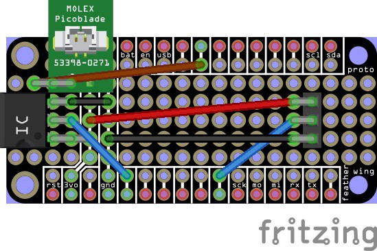
1Assemble the Proto Board
The components on the Proto Board should be assembled as shown below.
![]()
The guide to wire colors:
- Grey "wires" are solder bridges.
- The brown wire should be run on the underside of the board.
- The blue, black, and red wires should be run on the top.
Put them on in that order (though the actual wire colors are up to you) before adding the other parts.
The other three components can then be added in any order, but be sure that:
- Pin 1 of the sensor is at the "south" end, so it connects to the 3V bus.
- The right-angle headers are pointed toward the outer end.
- The Picoblade is also pointed toward the outside.
You can ignore the last two if you want to for some reason, but if you get the first one wrong the device won't work properly (if at all).
Wrist-Worn Fever Alarm
Monitor your (or a loved one's) body temperature, with a notification should it reach fever level.
Discussions
Become a Hackaday.io Member
Create an account to leave a comment. Already have an account? Log In.