 Nicholas Stedman
-
1Step 1
Assemble the Mocoder (and disassemble again).
Unpack the bits.
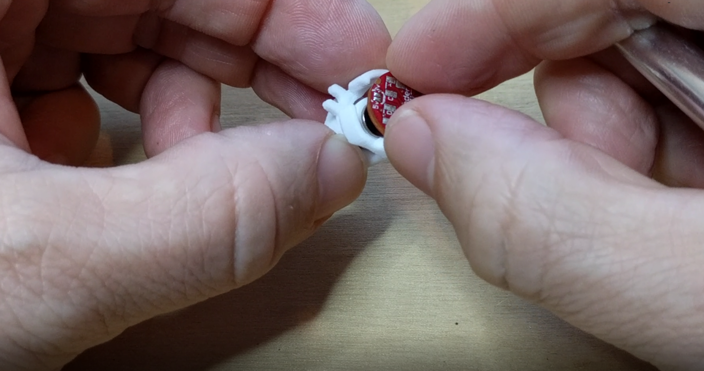
Line up the registration points on the plastic housing with the drillouts on the PCB. Place the PCB under the one wing.
![]()
Push down on the PCB and pull out on the other wing...the PCB will snap firmly into place.
![]()
The assembled Mocoder:
If you want to use the encoder in something other than a servo, you can now either solder leads to it as in Step 2, or solder the included 8 pin SMT header. This method uses the i2c interface, and AMS have been kind enough to provide an Arduino library that provides an API to all of the available functions.
Alternatively, for reading the position simply as an Analog Output from an ADC, you can just hook up power and ground, and read from the OUT pin (labeled O).
Now that you know how to assemble the Mocoder, you may want to disassemble it and reassemble it after you solder connections and fit it into your project.
-
2Step 2
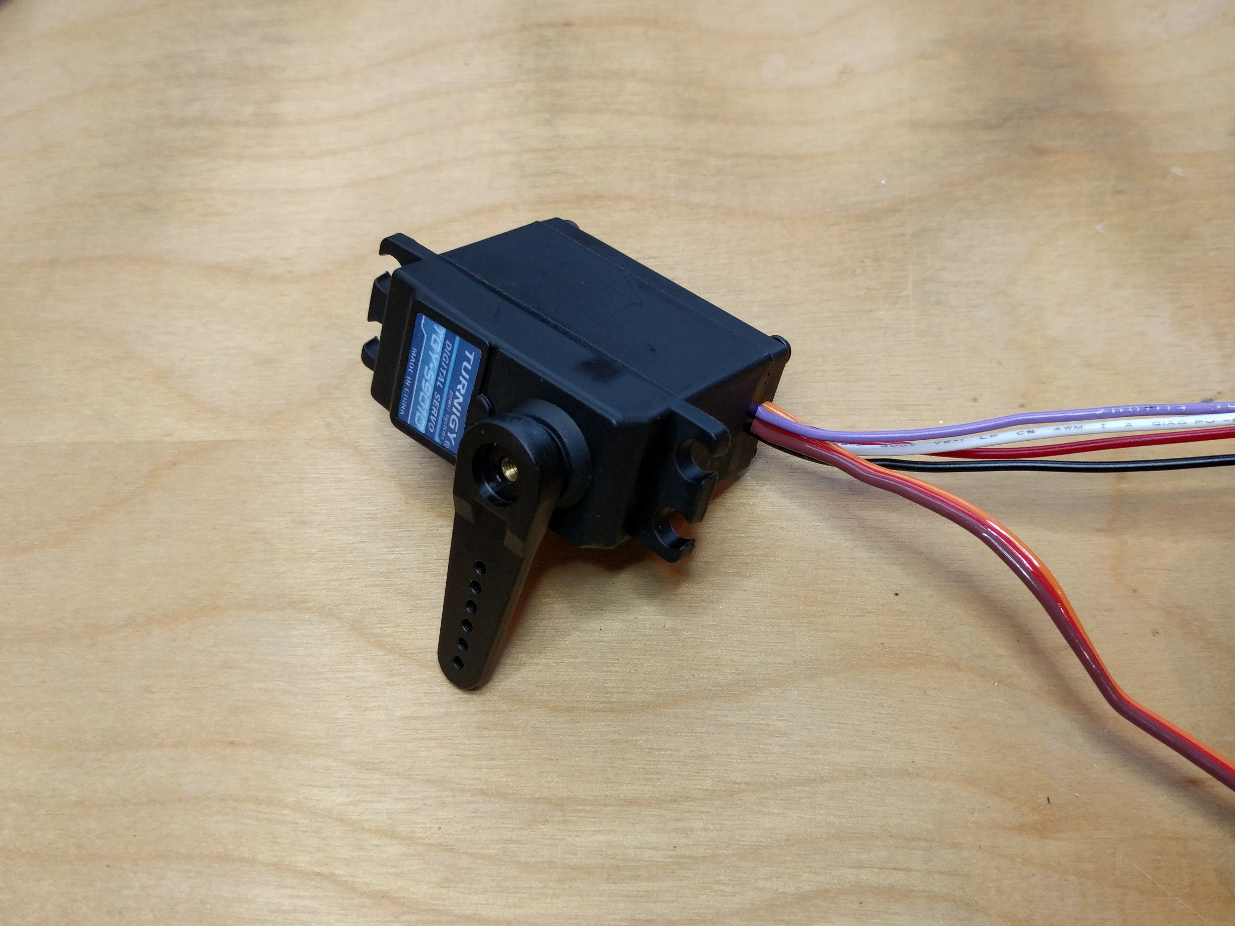
Solder leads to the circuit.
Solder leads to G (ground), 5 (5 Volts), D (SDA), C (SCL). Length depends on application, but a foot is good place to start.
If they are stiff wires, then bend them up away from the board.
-
3Step 3
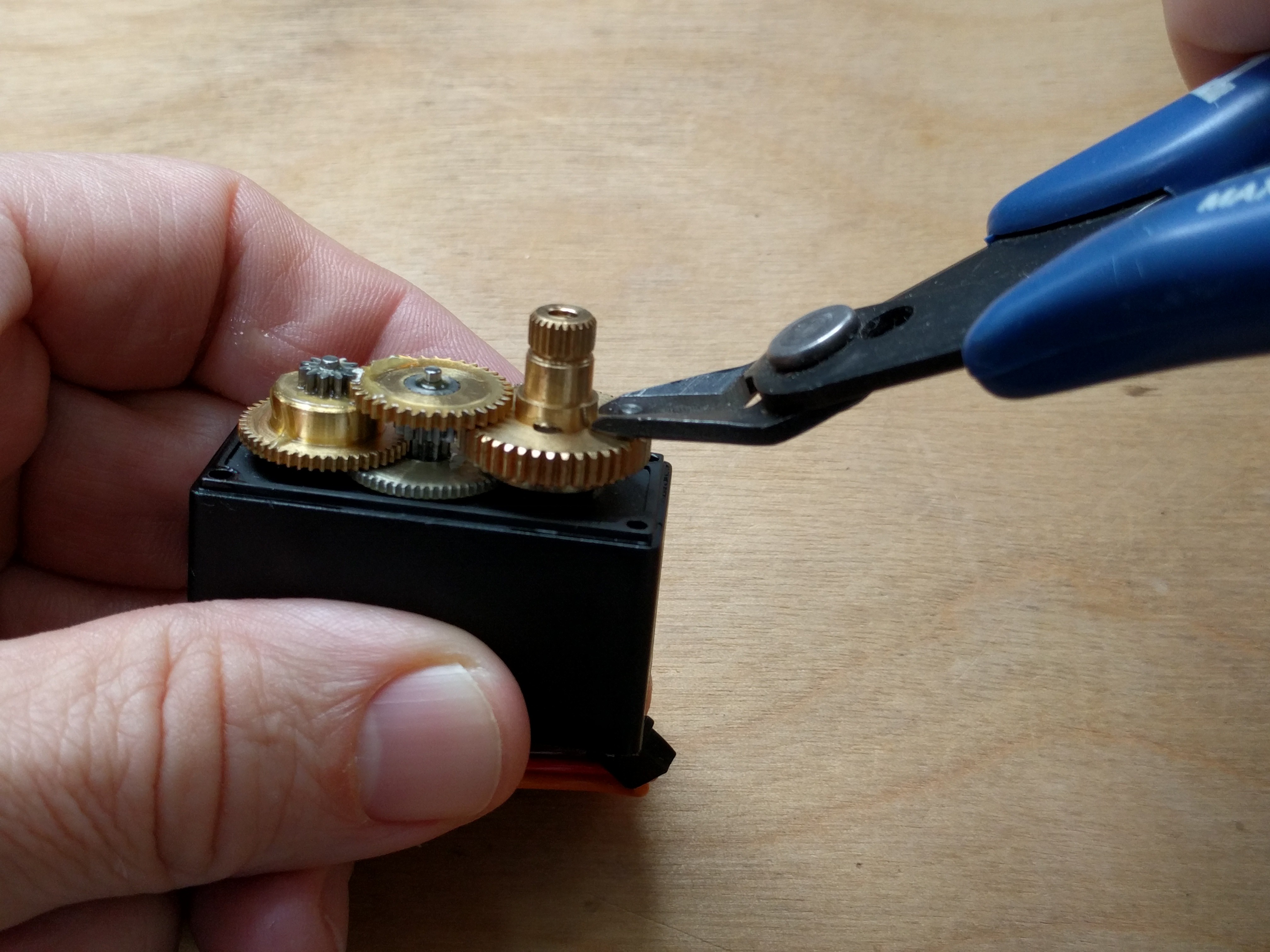
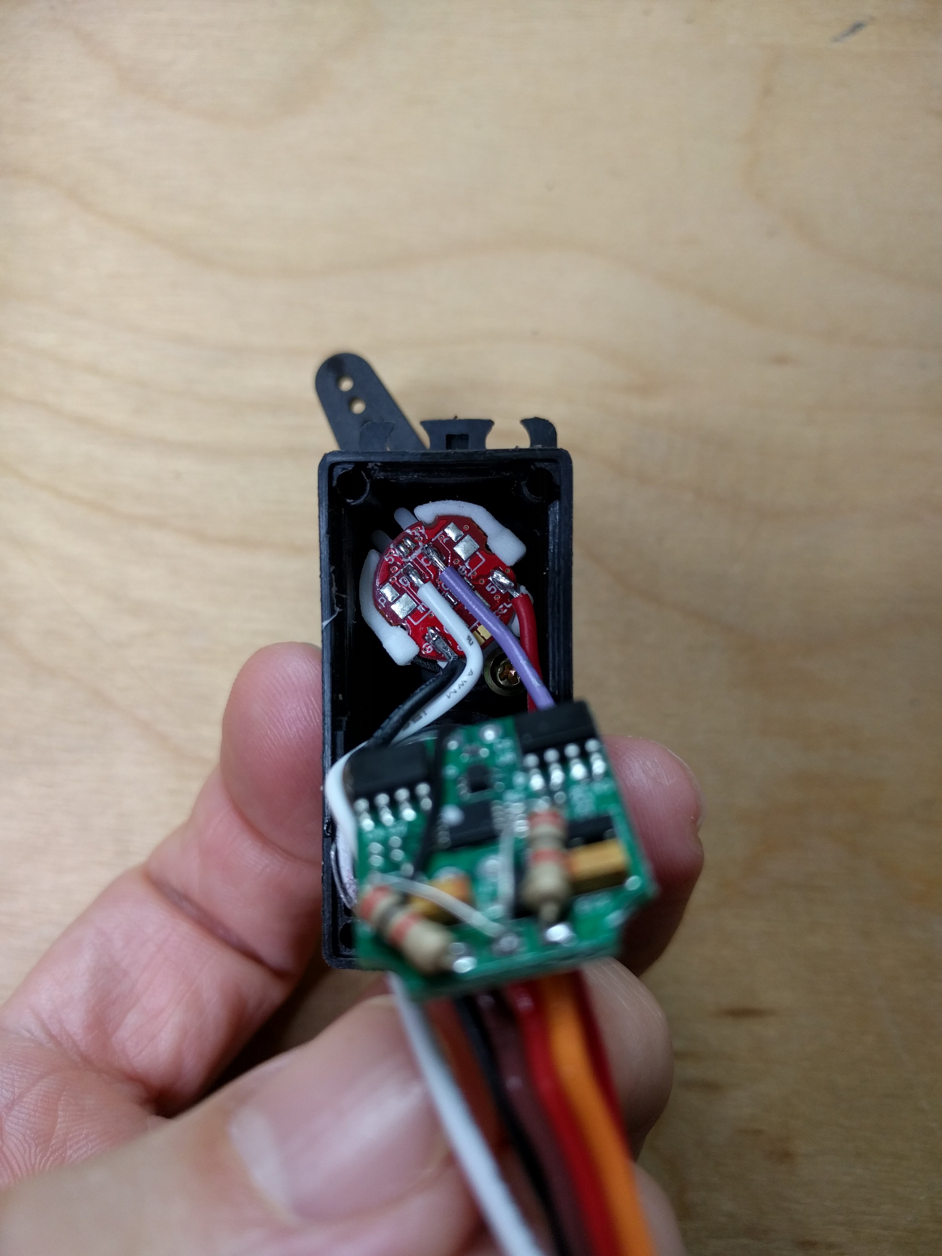
Open case and remove stop pin from gears.
Unscrew and remove the backside of the servo case
Remove the top of the case. Be careful not to drop the gears, as they are no longer held in place.
Remove the stopper pin from the pinion gear. Try using wire snippers to grip the sides, and using the tip of the snippers as a lever.
![]()
Replace the top cap over the gears, and tape it down while modifying the rest of the servo.
-
4Step 4
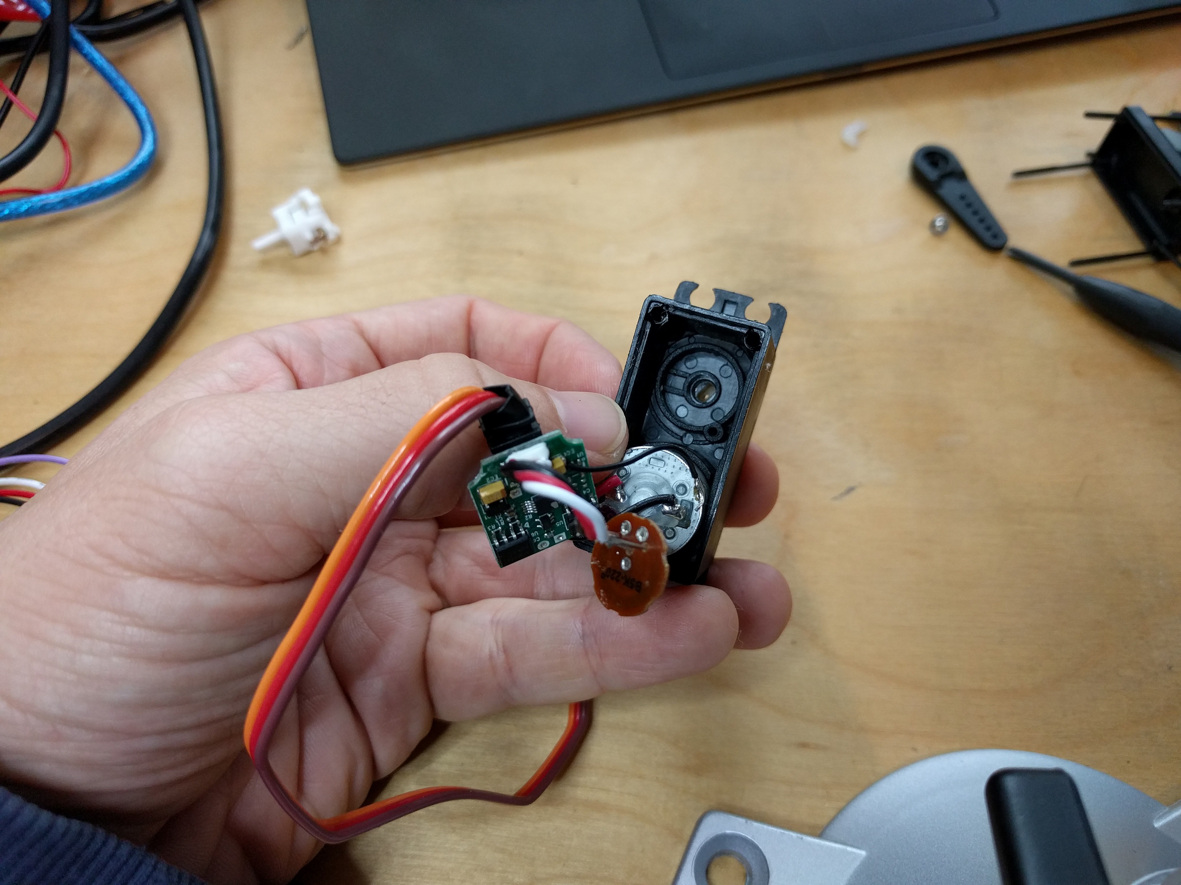
Remove the potentiometer from the case.
Pot removed...
![]()
-
5Step 5
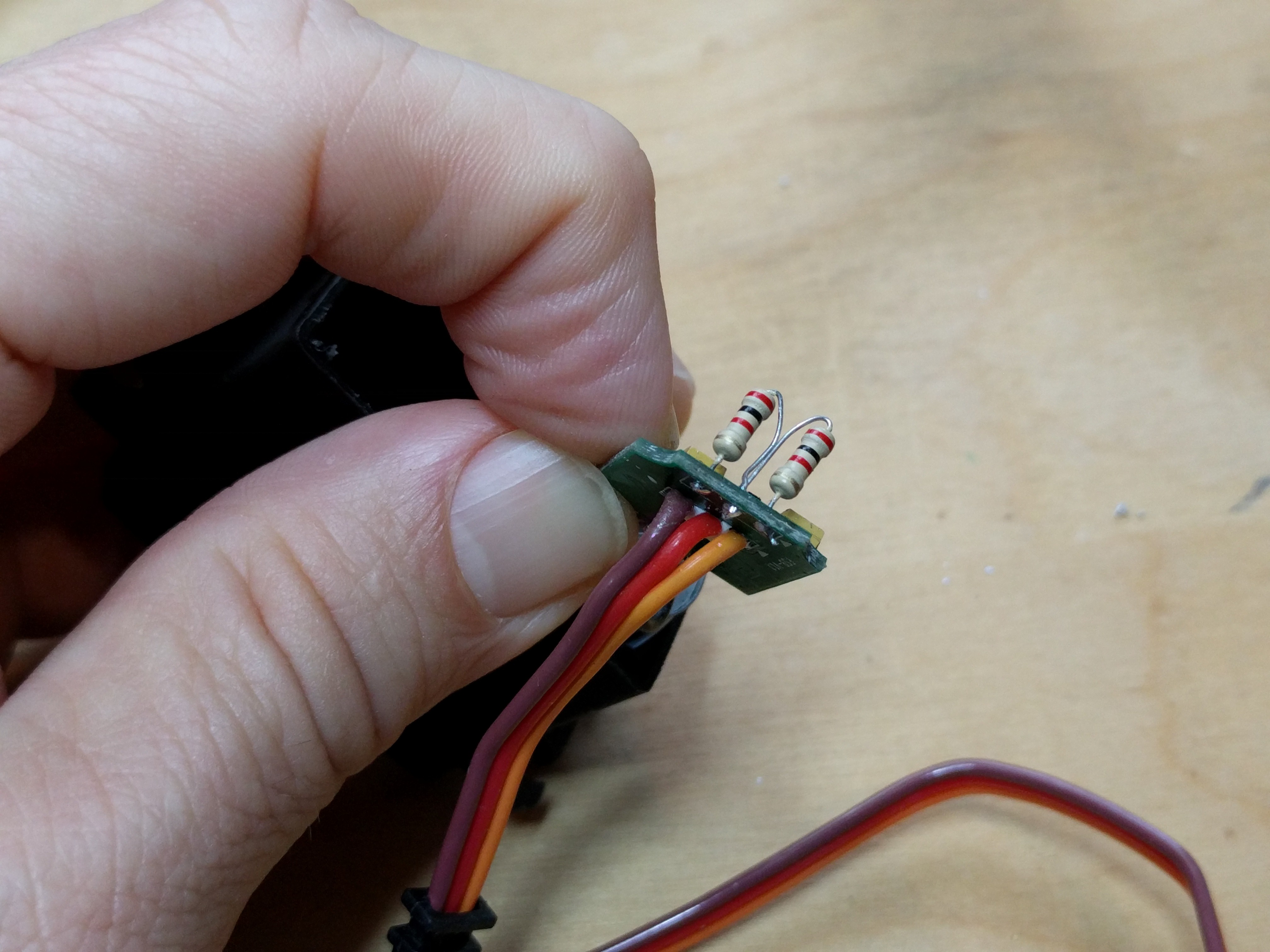
Replace potentiometer with voltage divider in servo circuit.
Desolder the pot leads from the servo circuit and replace with two ~2.4k resistors (other values will also work).
![]()
Bend the resistors over until flush with the circuit board to move them out of the way.
-
6Step 6
Slot in the mocoder and reassemble the servo.
Push the mocoder inside of the case. Line up one of the mounting wings with the screw hole, and use the small screw to secure the mocoder in place. One of the pads on the bottom of the mocoder should automatically line up with a slot inside the hole for additional stability. They can be trimmed if they actually obstruct placement.
When pushing in the housing, it's easiest to get the outer shell fastened down first. The spindle may pop out while you do this. After the shell is fixed push down on the spindle while slowly rotating it until it clicks into place.
Once the mocoder housing is fixed down, now pop in the mocoder circuit (as you did in Step 1)
![]()
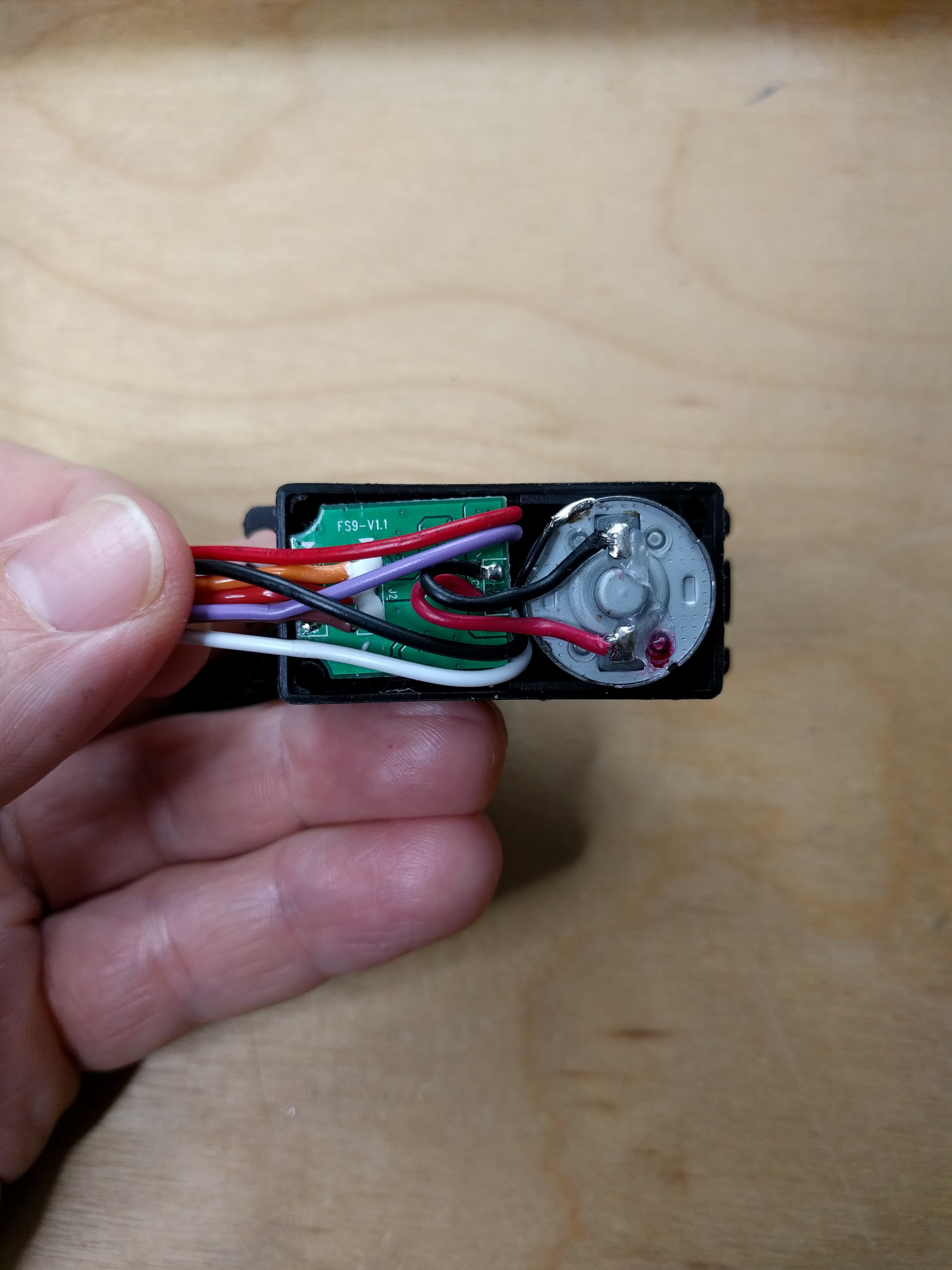
Now, it's time to reassemble the servo. Route the wire around the back side of the control circuit. I like to place two wires on either side.
![]()
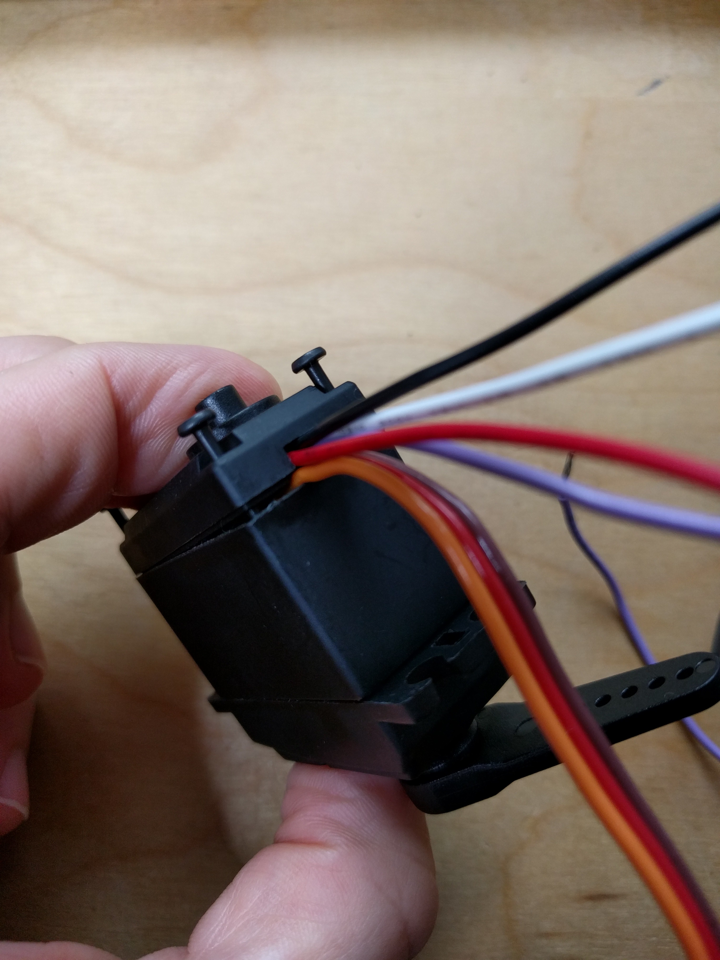
Place the bottom of the case back on the servo, and tighten up the screws most of the way. Stop to route the wires through the existing slot, making sure the wires aren't pinched. Then finish tightening the screws.
![]()
The reassembled servo.
![]()
-
7Step 7
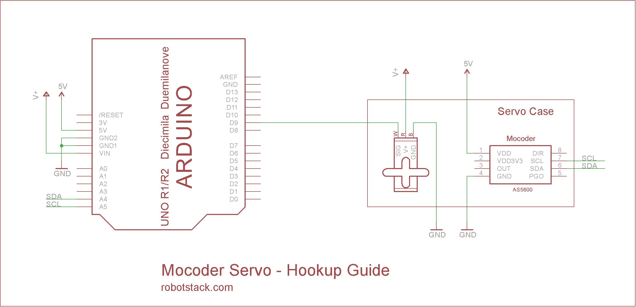
Wiring up to a Microcontroller (Arduino) and finding the hold position.
When a servo is modified for continuous rotation the 1000us to 2000us pulse sent every 20ms no longer controls position. It now controls the speed of rotation. Using an even voltage divider, as we have, causes a 1500us pulse to hold the position steady, and anything above that moving clockwise, and below counterclockwise. However because the resistors aren't precise, some calibration is required as the pulsewidth might be closer to 1530us, or some other value. To figure it out, use the program available here:
https://bitbucket.org/nsted/continuous_servo_calibration
It starts by outputting a 1500us value, and then allows you send different values over serial to home in on the value that brakes the motor, holding the position steady. Upload the code, disconnect USB and power, and then wire up circuit.
The connections for reading over i2c are as follows.
![]()
Now reattach your power supply (yes, use an external power supply, or else it might draw too much current over USB and shut down your computer), then reattach to USB.
Open up the serial monitor and start sending values between 1000 and 2000. You should see the motor change its speed and direction. Then try sending values around 1500 until you find the point at which the motor comes to a standstill. Record this number, as you'll need it in subsequent programs.
Ok, the servo is ready to go, so let's try out a program that explores it's ability to both rotate continuously and seek position. Download the following code, and upload to the Arduino:
https://bitbucket.org/nsted/mocoder_arduinoBefore uploading, click on the "motions" tab, and enter the value of the hold pulsewidth, that you found in the previous step. Then upload.
You should see the motor moving in 360 degree loops a few times, and then reversing.
-
8Step 8
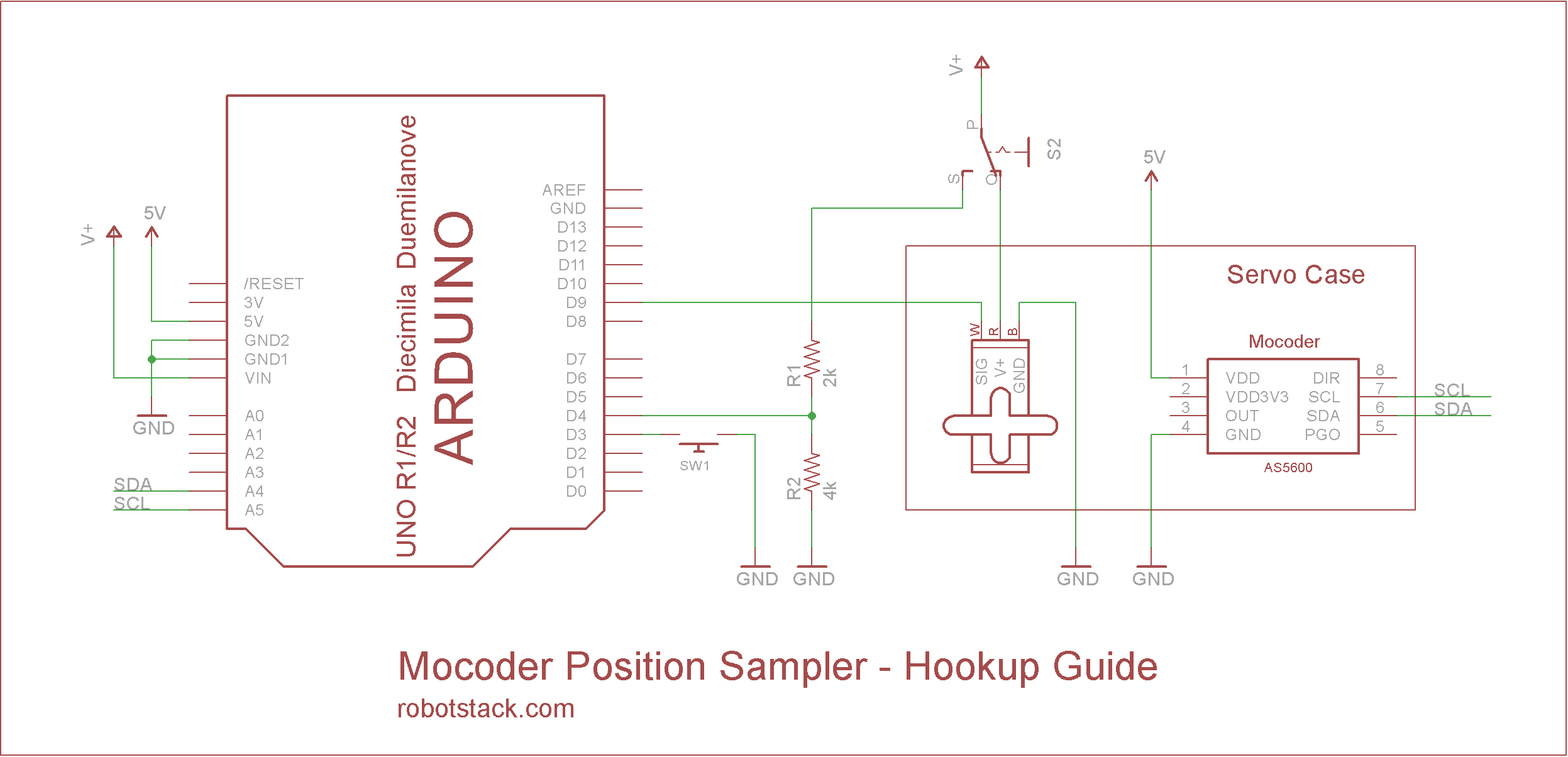
Sampling the servo's position, and playing it back.
Let's add a few more components to our circuit.
![]()
Notice the switch connected between V+ in the common position, the servo power input on one side, and the voltage divider on the other. This is the servo activation switch. When power is cut to the servo, the microcontroller receives a high signal at the same time, notifying it that the servo is deactivated.
Now we can manually reposition the servo and hit the push button to take a sample of the new placement. This sample will replace whatever position was previously stored in memory.
Before we can test this go to the top of main tab in your Arduino sketch and change the first #define from "#define BASIC" to "#define SAMPLER" and reupload the program.
-
9Step 9
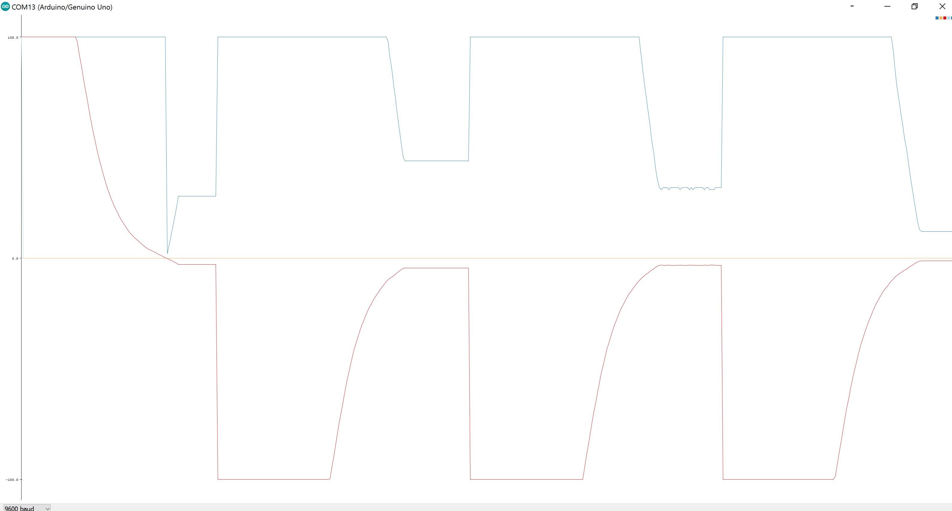
Tuning the PID controller to improve position seeking.
When the servo is first operated, it may over or undershoot its destination by a little or a lot. This depends on the voltage of the power supply, the speed, and the mass it is trying to move. We need to calibrate the servo's control system to improve accuracy.
For context, the program uses a PID controller for positioning. The Input is the gap between the position and destination. The Setpoint is the desired gap, which of course is zero. The Output is pulse width in microseconds of our servo signal, in other words the motor's speed. This setup means that as the gap decreases the motor slows down, and so the destination is anticipated.
We need to tune the PID's gain constants in to affect the servo's positional accuracy. These gains determine how much each of the Proportional Derivative and Intergral terms contribute. You'll find those gains at the top of the PIDHelpers tab.
Tuning can be a bit of a dark art, and there are more than one suggested approaches. One that I have found effective is to first zero out all the terms, and then raise the Proportional gain until the motor is coming as close as possible to stopping on point without overshooting. If that suffices, stop there. If not, raise the Derivative gain until you're satisfied with the result. I tend to not use the Integral term at all.
While tuning, you can observe the effects of your changes by uncommenting the call to plotPID() in the main loop. Then open up the serial plotter. You should see the results charted on screen. Unfortunately, Arduino's serial monitor doesn't include labels, so you'll have to look at the order of print statements in the function (in PIDHelpers) Alternatively, use the serial monitor with debugPID() to observe the numbers with labels.
![]()
-
10Step 10
That's it, have fun...
Explore your new servo. Attach it to something interesting. Rework the code as you like. Make a robot dammit. BTW, if you want to use multiple of these servos on the same microcontroller, you can always modify the circuit and code above to use the analog output available on the mocoder to read the position instead.
Mocoder - Magnetic Encoder
Build your own continuous servo, with an RC servo and a Mocoder Magnetic Encoder


 Remove the top of the case. Be careful not to drop the gears, as they are no longer held in place.
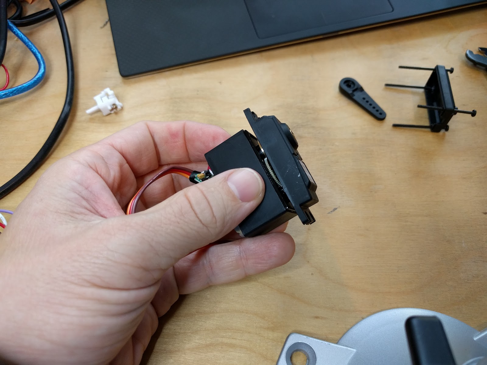 Remove the stopper pin from the pinion gear. Try using wire snippers to grip the sides, and using the tip of the snippers as a lever.

Discussions
Become a Hackaday.io Member
Create an account to leave a comment. Already have an account? Log In.
Sorry, I put in an unobvious place...I just added it in the tutorial as well (where I said it would be).
Are you sure? yes | no
I don't see the link to the Arduino code did I miss something?
Are you sure? yes | no