 kamalkedin123
Principle:
The laser security system works in the principle of light sensor effectiveness, the LDR sensor is used in the circuit. If the light of laser is blocked by any external things to reach the sensor, then the resistance of the LDR decreases results in the high flow of current across the circuit. The construction and functioning of laser based security system is very simple and highly effective the system can also be operated on battery on large scale. It is highly secured system.
Components Required:
- LM358 (Op-Amp IC)
- NE555 Timer IC (1)
- LDR Sensor (1)
- 10k Ohm Resistor(3)
- 220 Ohm Resistor (1)
- 10K Potentiometer (1)
- BC547 NPN Transistor (1)
- 100nF Capacitor (1)
- Push Button. (1)
- Small Buzzer
- Laser Pointer (1)
- Connecting wires (as required)
- 9V Battery (1)
- Bread board
Attention Here:
As we all know our world is suffering from highly infected pandemic disease COVID-19. So, for the awareness and social responsibility Utsource is providing 0 profit selling disposable medical things.
Please check out and wear masks when going out!
Get all the things from here
- Infrared Thermometer
- KN95 Masks(10 pcs)
- Disposable Surgical Masks(50 pcs)
- Protective Goggles (3 pcs)
- Disposable protective coveralls (1 pc)
- Disposable Latex Gloves (100 pcs)
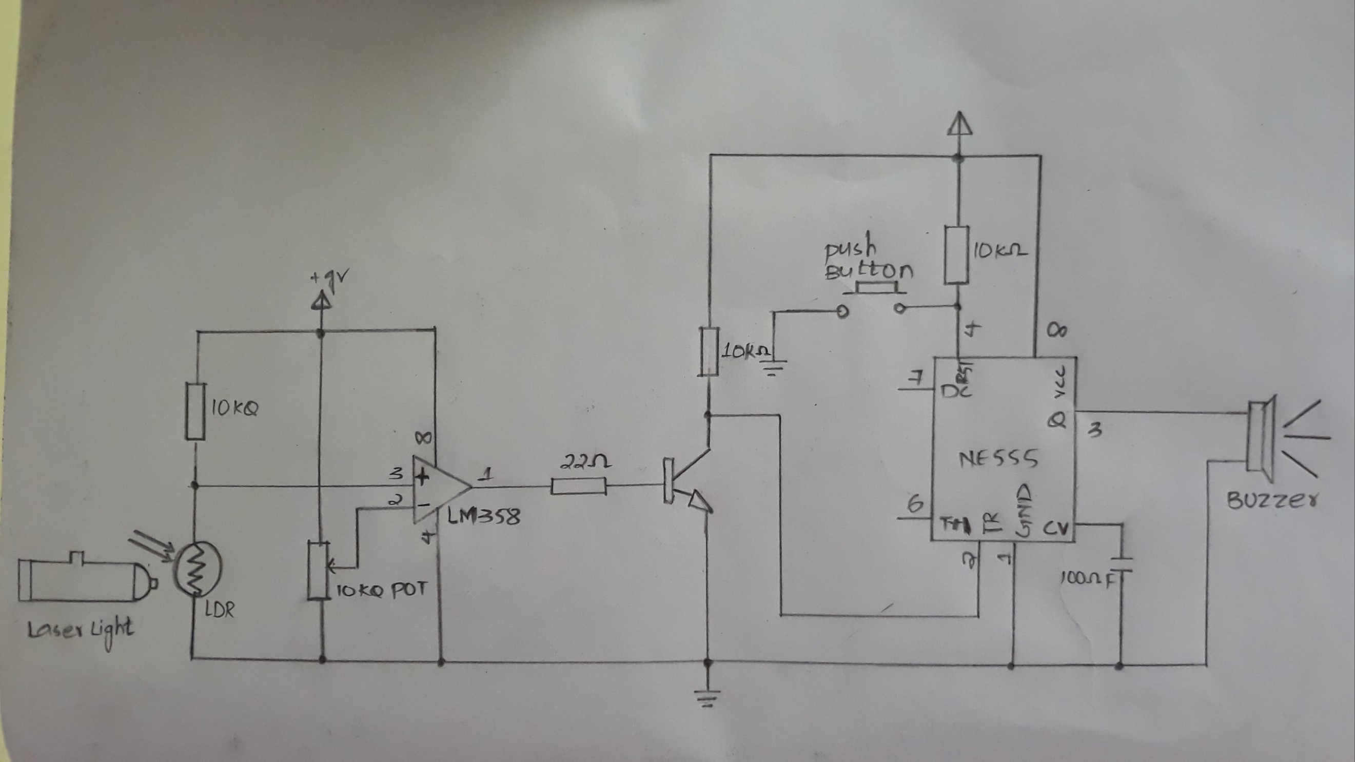
Circuit Diagram:
Procedure:
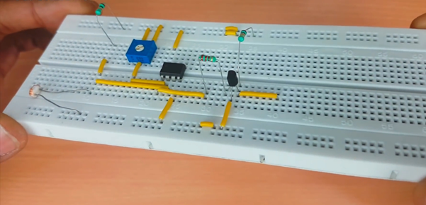
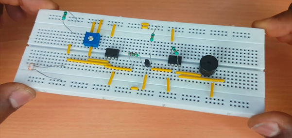
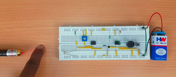
1. Insert 10k Ohm Resistor on the bread board as shown in the figure below
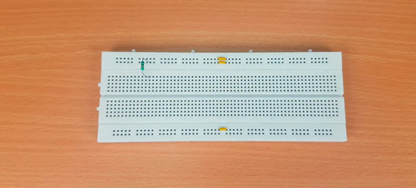
2. Connect one terminal of the resistor with LDR and another terminal to the positive rail of the bread board as shown in figure.
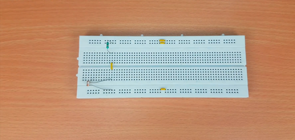
3. Now connect the potentiometer on the bread board and extend its terminal through wires
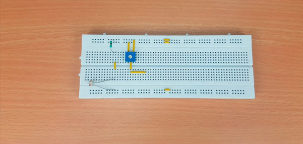
4. Now insert LM358 on the bread board with connections as per the circuit diagram
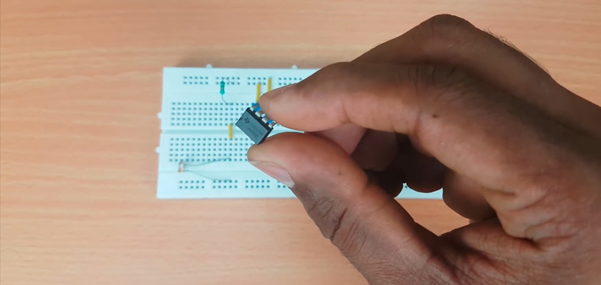
connect LM358 with potentiometer
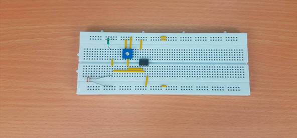
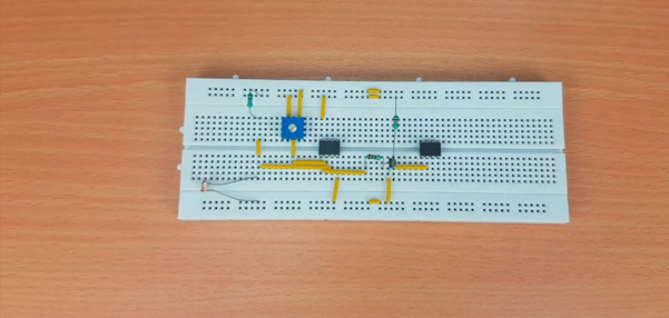
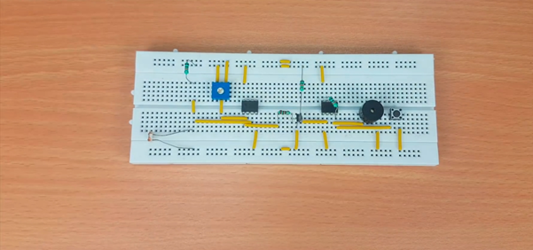
5. Connect 220 Ohm resistor on the bread board with Pin 1 of LM358
6. Now place the NPN Transistor on the bread board
with base terminal connected to the one end of 220 Ohm resistor.
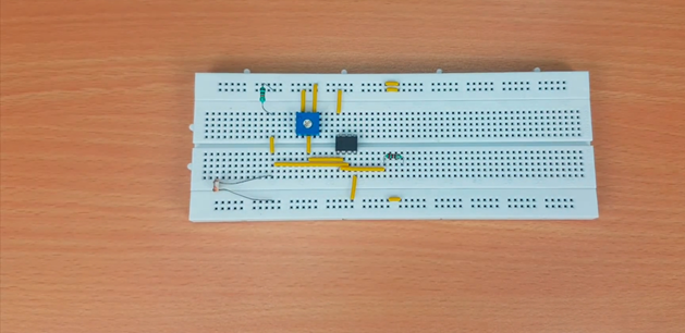
7. Now connect NE555 Timer IC on the bread board
8. Connect Pin 1 and Pin 5 of the NE555 IC to the negative rail of the bread board.
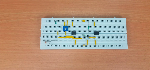
9. Now place 10k Ohm resistor on the bread board through Pin 4 and positive rail of the bread board.
10. Insert buzzer on the bread board and connect its one terminal to the ground and other terminal to the Pin 3 of NE555 timer IC as per the circuit diagram.
11. Connect the momentary push button to our circuit as shown in figure below
12. Connect 100nF Capacitor on the bread board
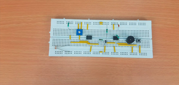
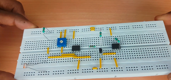
13. Now connect the rail terminals of the bread board as shown in the figure below

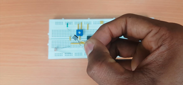
14. Connect the power supply with positive terminal to the positive rail of the bread board and negative terminal to the negative rail of the bread board and LED perpendicular to the LDR as shown.
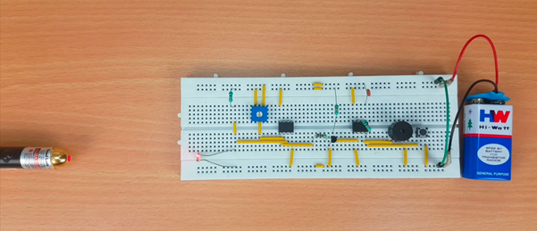
our circuit is ready.
15. When any object is get in between and light falling on LDR obstructs, the buzzer starts making sound and alerts for an emergency.
16. And when we push button it will again go to the stable state and buzzer stops making sound.

So this is the basic principle and functioning of Laser Controlled Security System.
Thank You.
 Abid Jamal
 muzi
muzi
 c00
c00