 Thornhill!
-
1Before we begin…
We'll be creating the Lou portion of the project. If anyone is interested in building the occupancy detector (using the magnetic door switch and light sensor) let me know!
A few more parts:
All the major components are listed in the component section, however we'll need a few more parts:
- Acrylic paint (optional).
- Mod Podge/PVA glue (optional).
- 30 AWG silicone wire (ideally various colours).
- 2 tiny screws (2-3 mm long, 1.3 mm 7/128ths thread?).
- M2 bolt (10 mm long) and nut.
- Medium sized paperclip (1 - 1.25 mm thick).
- The wire legs off of a resistor/capacitor/LED.
Tools:
These tools would also be helpful:
- Wire strippers.
- Flush wire cutters.
- Soldering iron.
- Tweezers.
- Pair of needle-nosed pliers.
- Screw driver/hex driver.
- Access to a 3D printer.
The plan:
Lou is 40 mm wide, 75 mm long, and 80 mm tall (1.6 x 3 x 3.25 in).
The cistern will contain the AirLift breakout board and a momentary tactile switch that pokes out of the top of the cistern lid, like the button for a toilet flush. This switch will act as the reset button for the microcontroller.
Speaking of micronctroller, the ItsyBitsy 32u4 5v board will rest on the bottom, under the cistern with the USB connector facing out of the back.
The NeoPixel will sit inside a specially sized inset within the toilet bowl. The servo has a space above the microcontroller, where the servo can rest on its side, it's arm poking out. It'll be fixed to the toilet via a single M2 nut and bolt.
The seat lid will attach to the toilet body via a straightened paperclip, while the stop sign will hang with the wire from a resistor/led/capacitor.
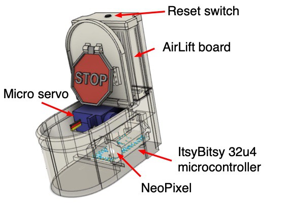
![]()
Screenshot of the CAD model of the toilet, complete with seat lid and stop sign in their upright positions. The toilet has been made slightly transparent to show the components within. Labels along the side point out the locations of the reset switch, the airlift board, the ItsyBitsy 32u4 microcontroller, the neopixel, and the micro servo. OKAY… let's make a miniature toilet!
-
2Print parts using a FFM 3D printer.
Lou is made up of several 3D printable parts, including the seat lid, cistern lid, and stop sign… so let's print all the parts!
You'll find 3D printable files in the file section and on the Lou GitHub page. There are also two .3mf files that will load all of parts using the settings I used.
You can use whatever colour you like (I chose silver because that was the lightest shade of filament I had. White would probably look very nice and would allow you to skip step 2).
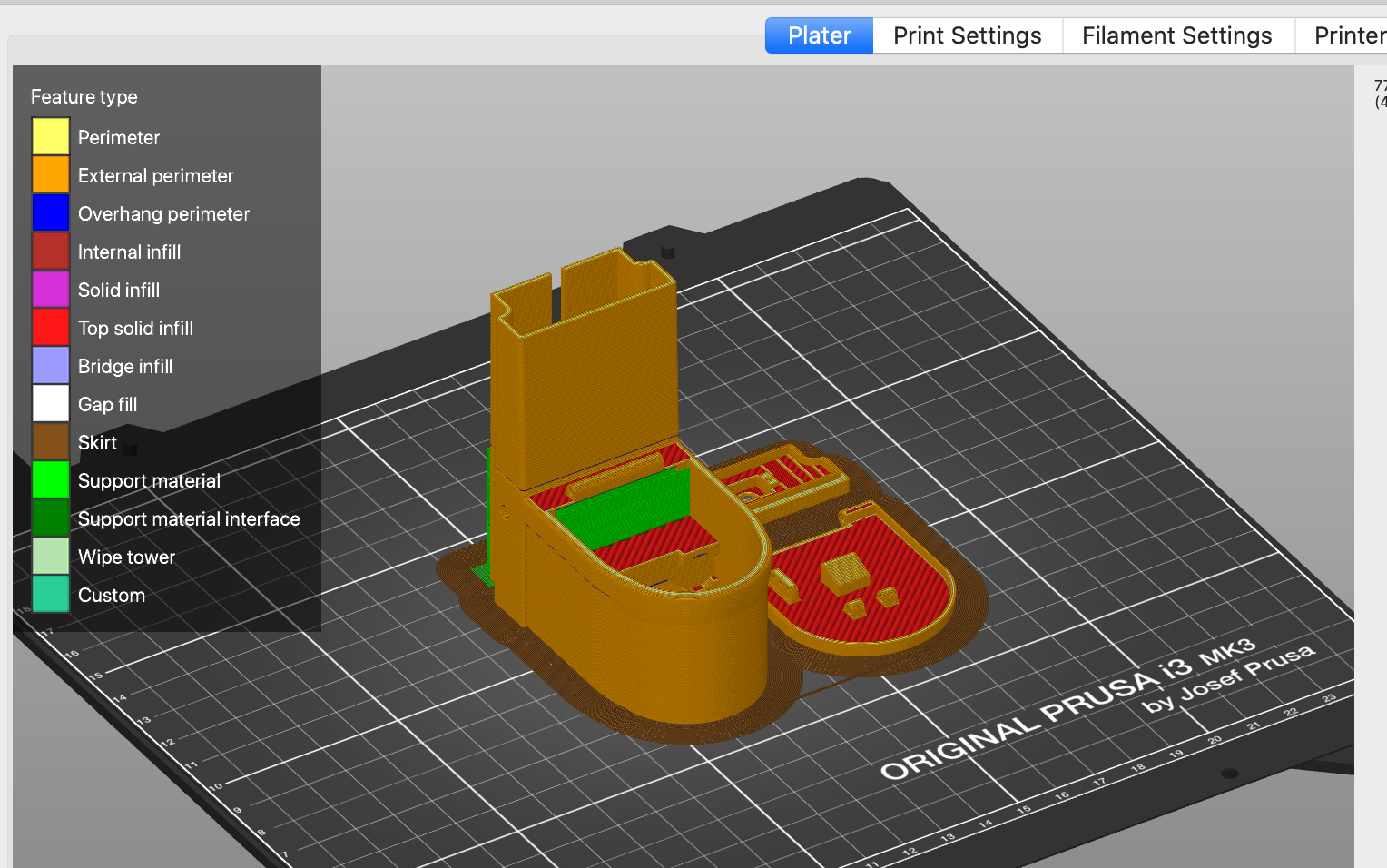
![]()
Screenshot of Lou's 3D printable parts loaded into slicer software, with different colours highlighting the different layer features. I printed everything together (except for the stop sign) using the following print settings on a Prusa i3 Mk2.5S:
Material: PLA Layer Height: 0.2 mm Infill: 15% Gyroid Supports: Support enforcer only used in the main Lou body, and only for the area that holds the servo Depending on your 3D printer and the settings you use, you should expect all of the parts to take just over 4 hours to print for about 50 g of filament.
Stop Sign:
The stop sign was designed to be printed in two colours (although you can print it using just one). For a sign that really pops, start with a red filament and add a colour change right before the text layer starts. Changing to a white or silver filament colour really helps to highlight the text (plus it'll make it look like a stop sign!).
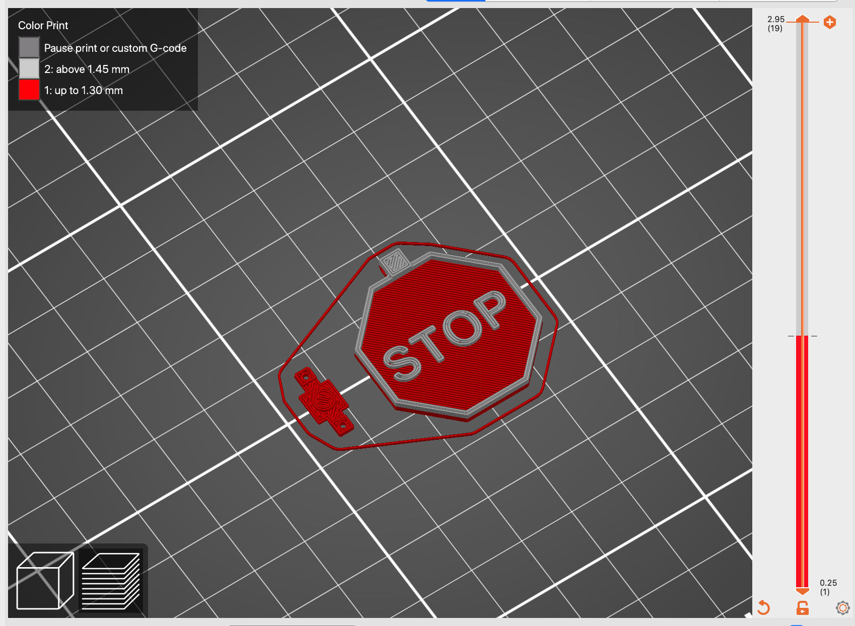
![]()
Screenshot of the stop sign part loaded into slicer software. A colour change setting has been used, with the slicer showing the background layers using a red filament, and the upper layers (with the text and border) using a silver filament. -
3Clean & Paint parts (optional).
Clean up prints:
Carefully remove supports and clean up the 3D printed parts. Pay close attention to the holes for the seat lid, using a needle or very fine drill bit to make sure the holes are open and will be able to accept the wire we'll be using later on.
Paint parts:
If you're like me and started with a filament colour that's not the final colour you want, then you'll have to paint your freshly printed parts.
I painted Lou, the cistern lid, and the seat lid using white acrylic. Several coats with some light sanding between coats is all that's needed. I found that painting the inside of the toilet bowl and the underside of the toilet seat white helped to reflect the glow of the NeoPixel.
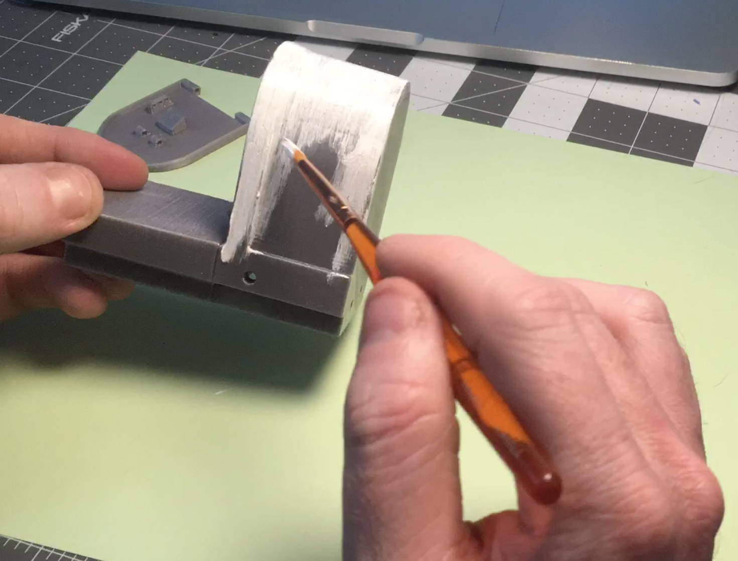
![]()
Photo showing me mid-way through painting the grey Lou the Toilet part white using acrylic paint. Extra fancy:
One dry, use some Mod Podge/PVA glue to seal the paint and add some extra gloss. This should make Lou gleam like the porcelain throne it wants to be!
-
4Prepare the wires!
Now onto the electronics stuff! We'll be cutting and tinning several lengths of wire for our various components. I used 30 AWG silicone wire because it's a dream to use and easy to bend and thread.
Using different coloured wires will also make the next few steps a lot easier when we have to route wires.
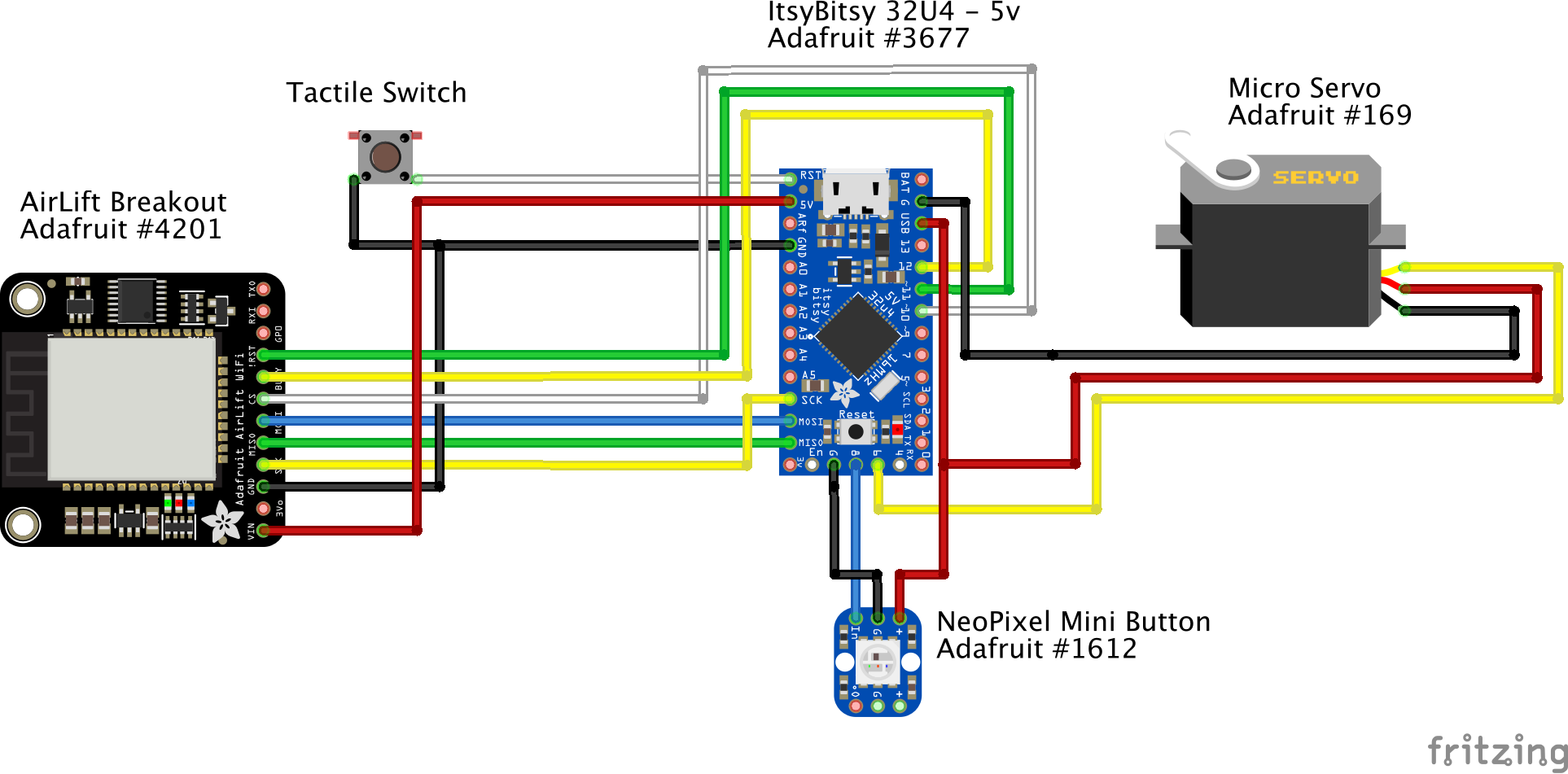
We'll be following this schematic (including the wire colours).
![]()
Colourful graphic schematic for Lou the Toilet, showing the different components and wire connections. Generated using Fritzing. Airlift and Reset Switch
We'll need 10 wires, approximately 5 inches long, with their ends stripped and tinned.
NeoPixel and Servo
The NeoPixel requires 2 short wires (< 2 inches) for ground and data-in, and 1 longer 5 volt wire (~ 3 inches).
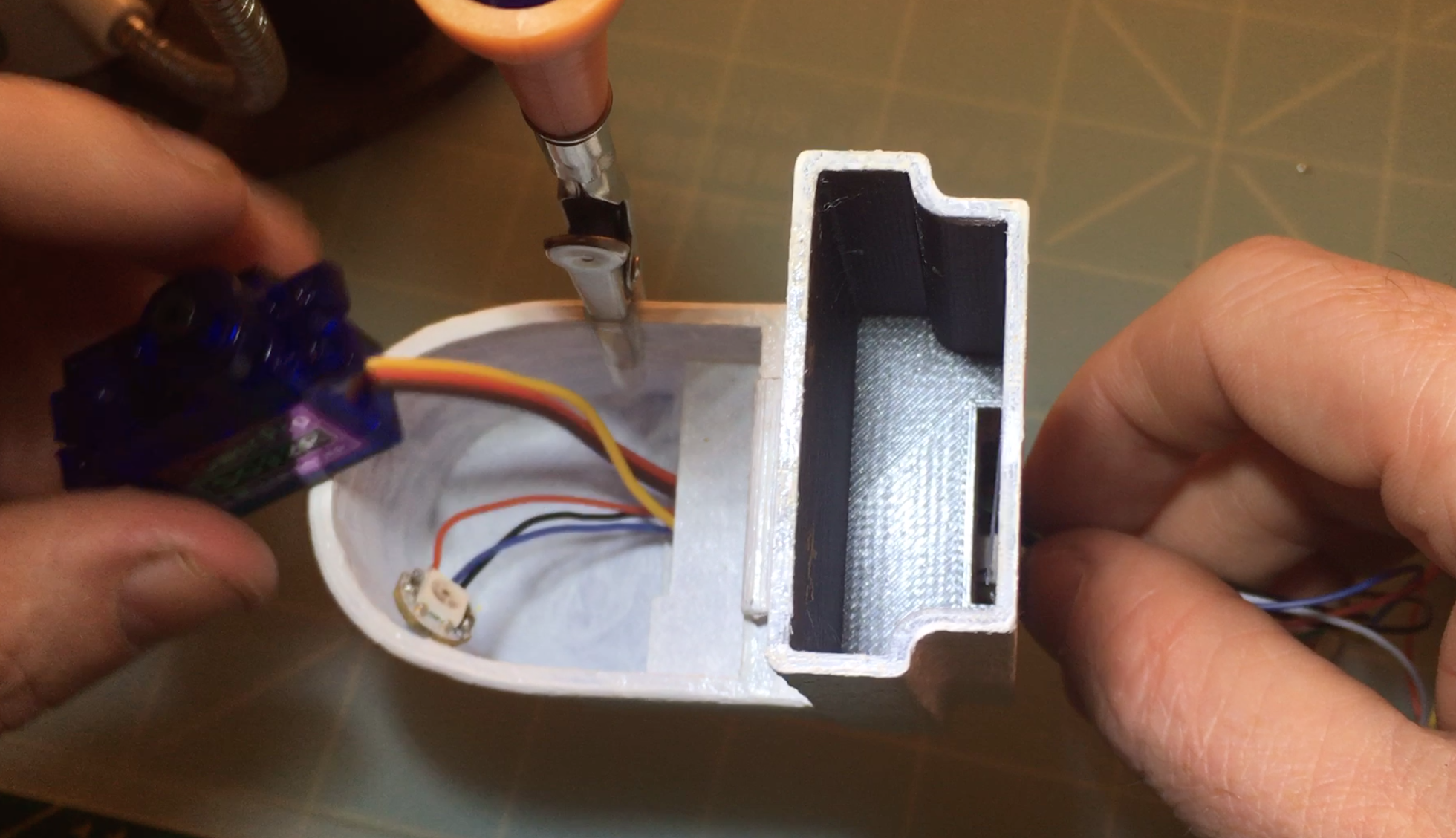
The servo comes with wires and a connector already attached. We won't be needing the connector, so snip it off using wire cutters, leaving about 4-5 inches of wire (enough for the wires to pass through the toilet bowl and out of the back, where we'll be soldering it to the ItsyBitsy in a later step). The wires are joined together, so carefully pull them apart.
Strip and tin all wires.
-
5Solder the wires to the ItsyBitsy
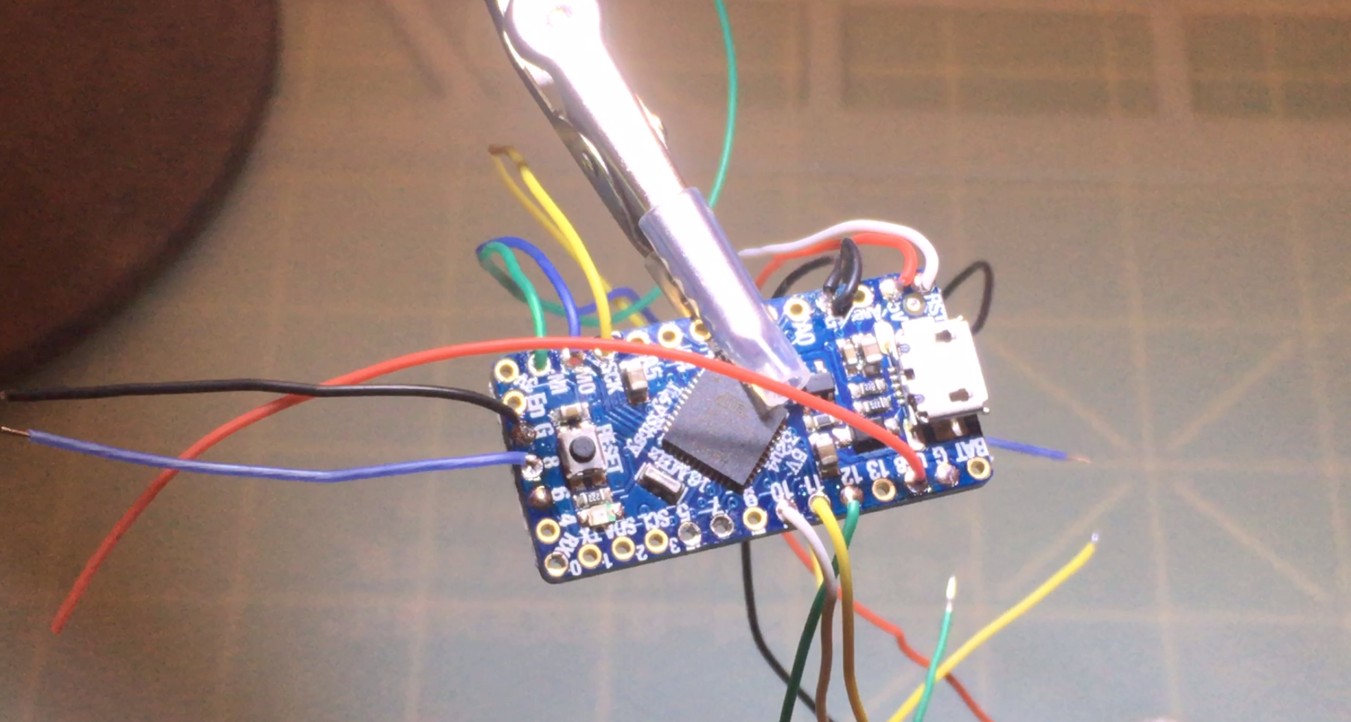
Following the schematic, solder all of the cut wires to the ItsyBitsy microcontroller. I found it was easier for later steps to keep wires grouped by component and whether they were coming from the right or left side of the board.
The reset switch and Airlift board share the same ground pin. With 30 AWG wire both of them should slip easily into ItsyBitsy's ground pin for soldering.
![]()
The blue rectangular ItsyBitsy microcontroller held by a hobby arm. Different coloured wires are soldered to pins on the ItsyBitsy's edges. Solder the servo wires last, making sure to position the servo on its side inside the toilet bowl first, with the ground and 5 volt wires coming out of the back. From here you can solder the two wires to the ItsyBitsy. Leave the servo signal wire unsoldered and inside the toilet bowl for now.
The servo and NeoPixel share the same USB pin, however since the servo's 5 volt wire is a lot thicker than 30 AWG, it can be a bit more difficult to solder both of these wires into the pin together (although not impossible!).
![]()
All the wires soldered to the ItsyBitsy, including the two ground and 5 volt servo wires coming out of the back of the toilet (also pictured) -
6Place the ItsyBitsy into the toilet.
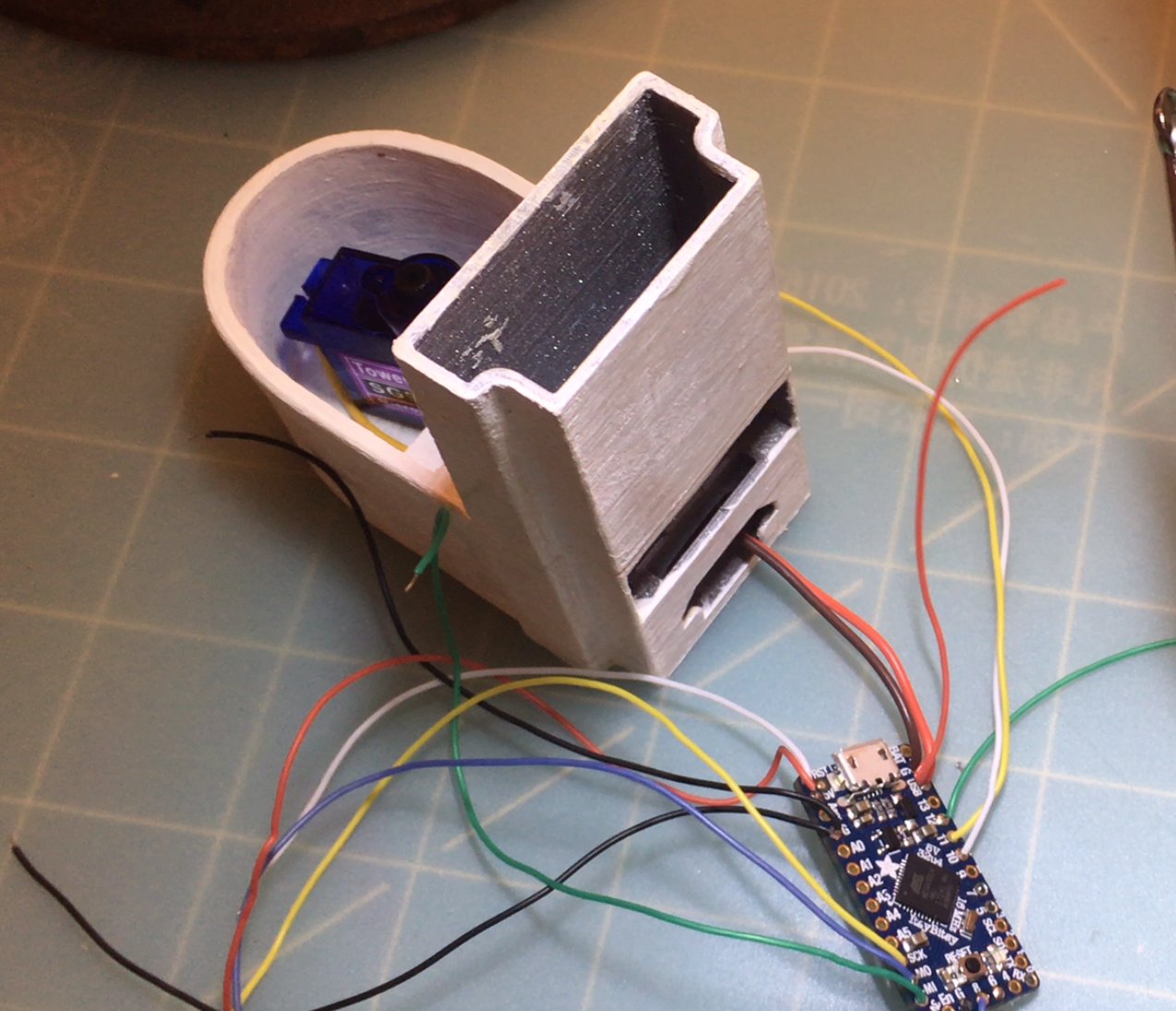
With the wires done, insert the ItsyBitsy into the toilet from the back, with the micro USB connector facing out.
Be sure to keep wires roughly grouped together, with the NeoPixel wires pushed out into the toilet bowl, and the Airlift and reset button wires coming out of the back. A pair of tweezers makes sorting out wires a lot easier.
![]()
Looking down at the toilet, with the ItsyBitsy inserted. Different coloured wires for the AirLift board and reset button routed out of the back, while wires for the servo and NeoPixel are routed out of the toilet bowl. Also shown is the underside of the NeoPixel PCB, showing the 5v (+), Data in (DIN), and ground pads. Soldering the NeoPixel and Servo
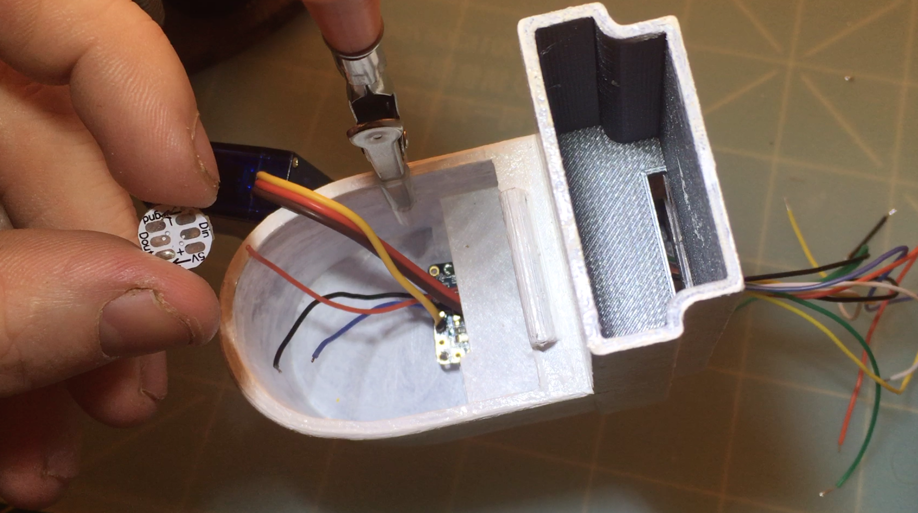
Push the ItsyBitsy into the bowl slightly, and find the 5 volt, data-in, and ground wires for the NeoPixel. Solder them to the underside of the NeoPixel PCB on the relevant pads (pre-tinning the NeoPixel pads first helps to make a quick solder job… which helps, as you need about 3 extra hands for this part!).
With the ItsyBitsy still pushed into the bowl, solder the servo's signal wire to pin 6 of the ItsyBitsy.
Once done, place the ItsyBitsy back into place. Press the NeoPixel into the insert next to the ItsyBitsy, with the LED facing out. Carefully push the servo and NeoPixel wires next to the ItsyBitsy so they're nice, tidy, and out of the way.
![]()
Looking down at the toilet with the ItsyBitsy pulled back into position, and the NeoPixel and servo all soldered up. -
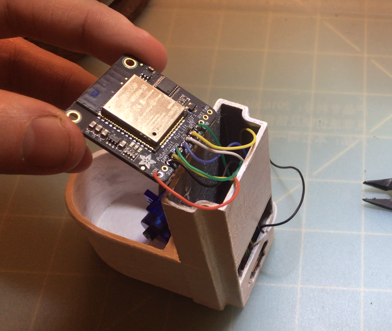
7Solder the Airlift board & reset switch.
With the wires coming out of the back, it's time to thread them into the cistern through the wire holes.
Note: I've recently updated the Lou CAD model to include a narrow gap on the back that makes this part slightly easier.
The wires should be long enough to poke out of the top of the cistern, with enough slack so you can solder them to the AirLift board easily. Follow the schematic and solder the wires to the relevant pins (making sure you solder the correct wires!).
If you've used different coloured wire and kept the wires in a rough order this step should be pretty easy!
![]()
Looking down at the toilet with the different coloured wires now coming out of the cistern and soldered to the black AirLift wifi board. Once soldered, slip the Airlift board and its wires into the cistern. Keep the reset switch hanging out for now.
-
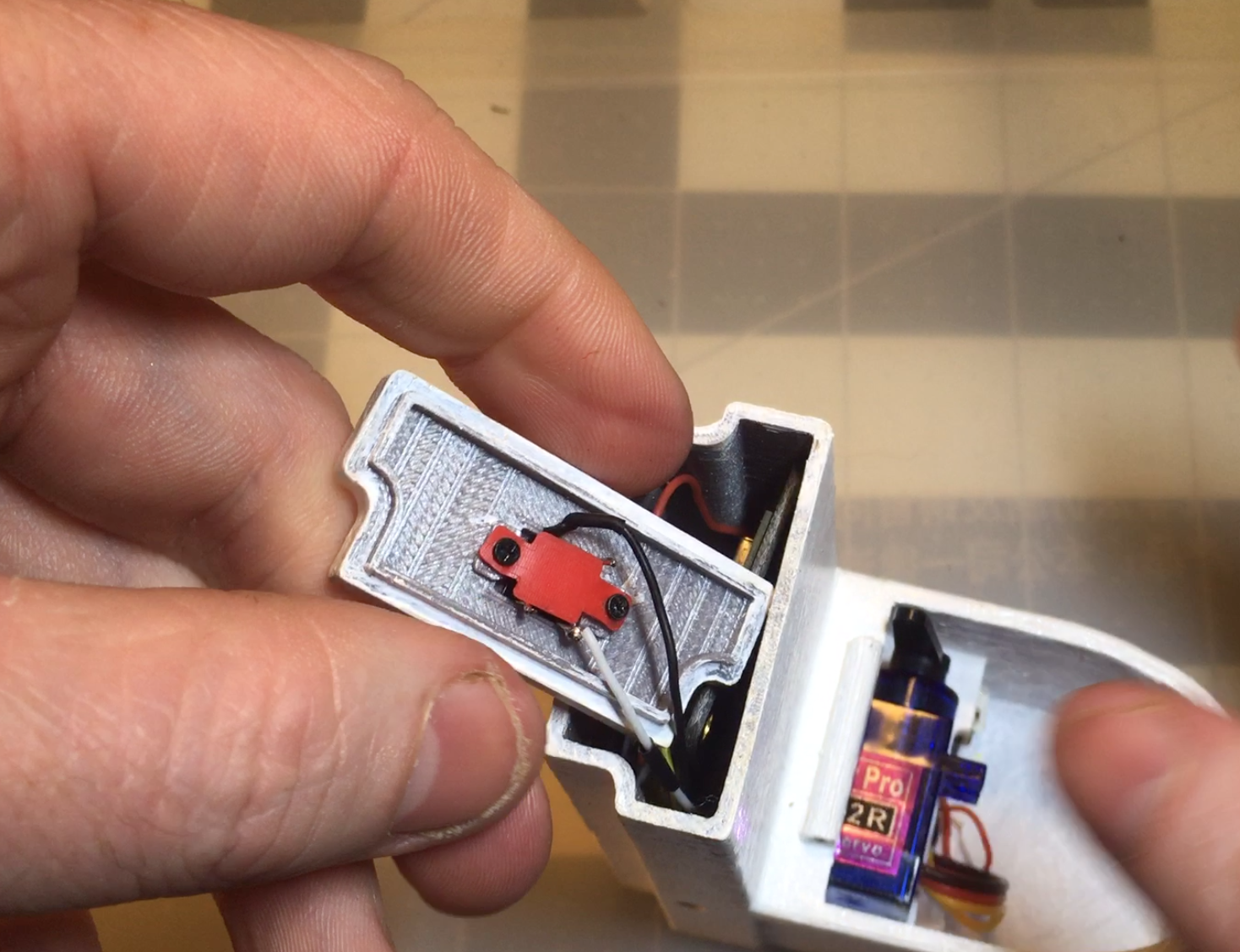
8Connect the reset switch.
The cistern lid requires a tactile momentary switch with a long actuator. The one I used came out of an old phone and was 9 mm tall, which… is a bit too long! I carefully cut off a few mm's off of the end.
To keep the reset switch attached to the cistern lid we'll be using the button plate and two tiny screws.
Insert the switch into the hole and recess in the cistern lid. Add the plate on top and screw in place.
The cistern lid is now done! Place the lid on top of the cistern. It should be a snug fit.
Note: The holes for the button plate are a little undersized. You might find it easier to widen the holes in the plate first before attaching it to the underside of the cistern lid.
Further Note: I'm not entirely sure on the dimensions of the screws I used (since I pulled them out of a drawer that contains the scavenged hardware of many dead electronics). Tiny screws that are about 2-3 mm long, with 1.3 mm (7/128ths) threads should work. I'll update this section when I can source exact parts.
Extra Further note: I'm going to be playing around and designing a screw-less version of the cistern lid, where the momentary switch can be snapped into place… making the previous notes pretty moot!
![]()
Looking down at the cistern lid, turned upside down to show the tactile switch attached into place with 2 screws and a red button plate. -
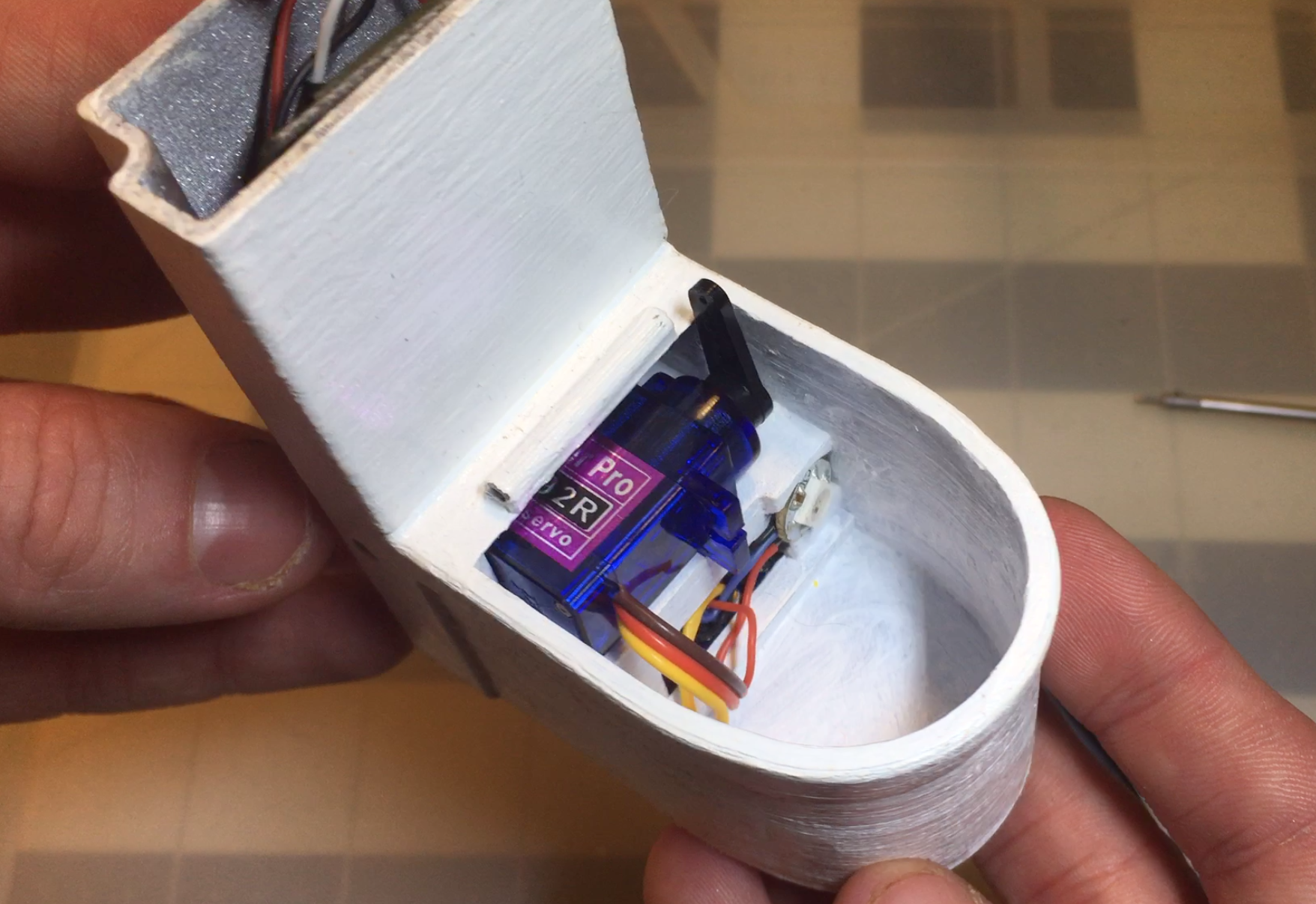
9Fix servo, attach arm.
Find the 0 ° or mid position on the servo. The following code can help you do this.
#include <Servo.h>

Servo myservo;  // create servo object to control a servo

void setup() {
  myservo.attach(6);  // attaches the servo on pin 6 to the servo object
  myservo.write(0);
}

void loop(){
}
Once you've located the mid position, with the toilet facing you, turn the servo so it rests on its side, with the wires on the left hand side and the shaft on the right. Attach the arm to the shaft so it points up and out.
![]()
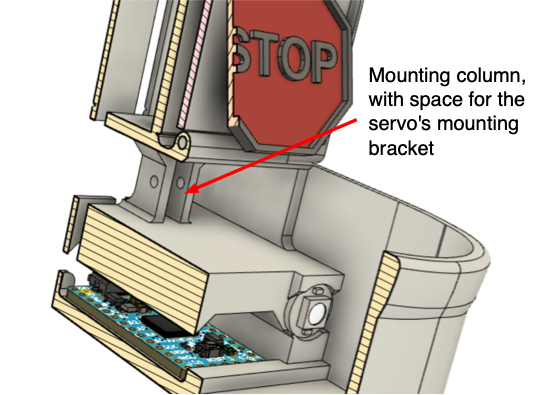
Looking down at the toilet with the blue micro servo in position, black arm attached and in the upright position. ![]()
Labelled screenshot of the 3D CAD model. A cross-section of the model shows the mounting column, with space for the servo's mounting bracket. The servo's mounting bracket should slide into a recess within the toilet (see image above). This will place the mounting bracket in the right position to insert a 10 mm long M2 bolt through the mounting column and bracket.
This next bit is a little fiddly! Using the hole on the side of the toilet, insert a thin screw/hex driver and start screwing in the bolt while holding the nut in place. You shouldn't need to screw down too tight, just enough to prevent the servo from sliding forwards.
Note: You might find it necessary to remove the servo's other mounting bracket (the one unattached in the toilet bowl) to prevent the stop sign from getting caught. I later removed mine using some flush cutters.
-
10Attach stop sign.
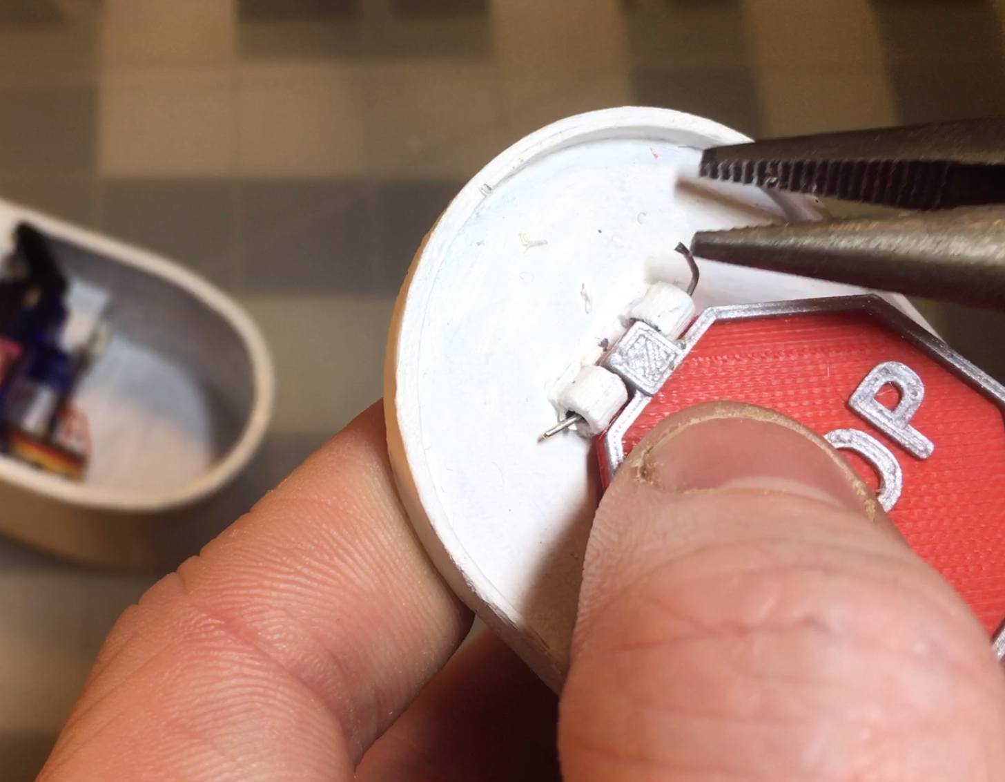
The stop sign attaches to the underside of the toilet seat lid using stiff wire snipped off of the leg from a LED/resistor/capacitor. Using pliers, add a 90 ° bend on one end.
With the stop sign positioned between the two hinge mounts, carefully slide the wire through the mounts and the stop sign. This bit can be really fiddly and might take several attempts. Using pliers, adding a slight curve to the wire, and ensuring the holes are clear help!
![]()
Carefully threading wire through the mounting holes and stop sign using pliers. Once threaded, add a bend to the end of the wire, snip to the correct length, and position the bent ends out of the way of the sign.
The sign should swing relatively easily. If it doesn't, you might need to straighten the wire a bit… or shave off a little bit of the plastic/paint from the hinge mounts.
Lou the Toilet indicator!
Bathroom occupancy detector & indicator using Adafruit IO and a cute lil' toilet…
Discussions
Become a Hackaday.io Member
Create an account to leave a comment. Already have an account? Log In.