M. Bindhammer
-
Power supply considerations
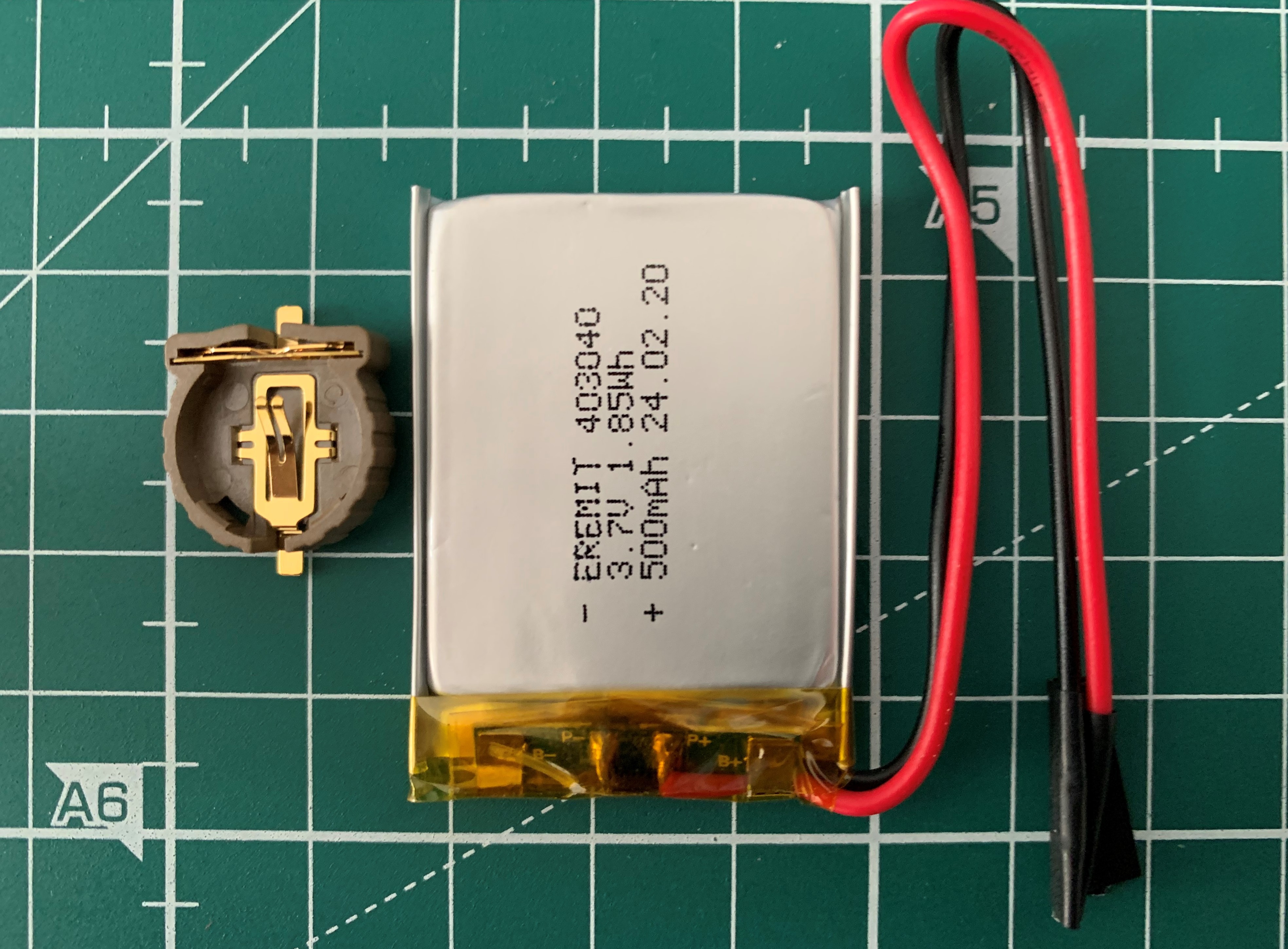
04/25/2020 at 13:36 • 0 commentsI think for Quattro I will use a dual power supply. A CR1220 for the RTC and a LiPo for the rest. I got some ultra thin 3.7V LiPo's with an integrated protection circuitry.
- 40.8 x 30.2 x 3.8mm
- Protected against overcharging > 4.25V
- Protected against discharge < 3V
- Rated voltage 3.7V
- Capacity 500mA
Should fit nicely on one side of a 50 x 50mm PCB together with the coin cell holder, the charging circuit, USB connector and boost converter:
![]()
-
It's not a display, it's a touchplay
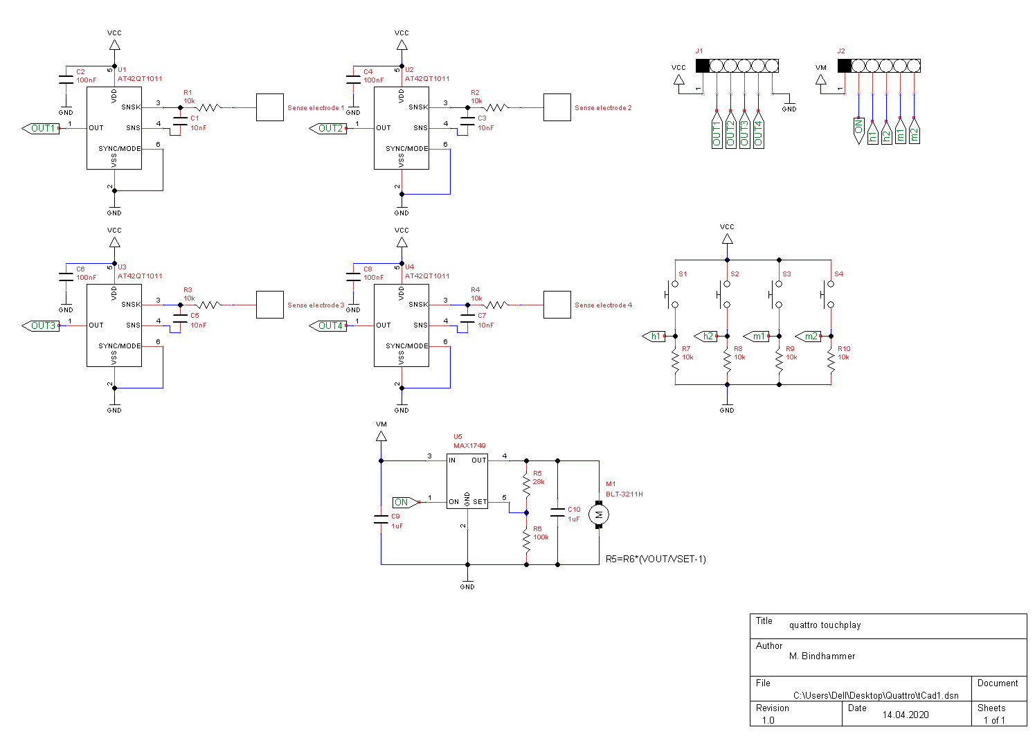
04/14/2020 at 17:23 • 0 commentsThe watch will consist of two PCBs. Started with the upper one and created the schematic. Also wanted to order laser cut and surface engraved acrylic glass to cover the upper PCB, but was not possible. Acrylic glass is temporarily unavailable, needed for spit protection in shops. Just ask myself why black acrylic glass is also not available.
![]()
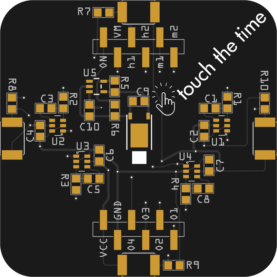
Touchplay PCB routed, work of a long day. Bottom view gerber rendering. The four circular touch pads are on the top. Pager motor is in the PCB center. No ground planes on top and bottom. Not sure if I need to shield the motor area. We will see.
![]()
Nice looking boards from JLCPCB. Forgot to include the stencil though. Need to re-order...
![]() A couple of days later I got the stencil. As usual for JLCPCB completely oversized. Fortunately the stainless steel stencil can be easily cut to the desired size with a pair of scissors.
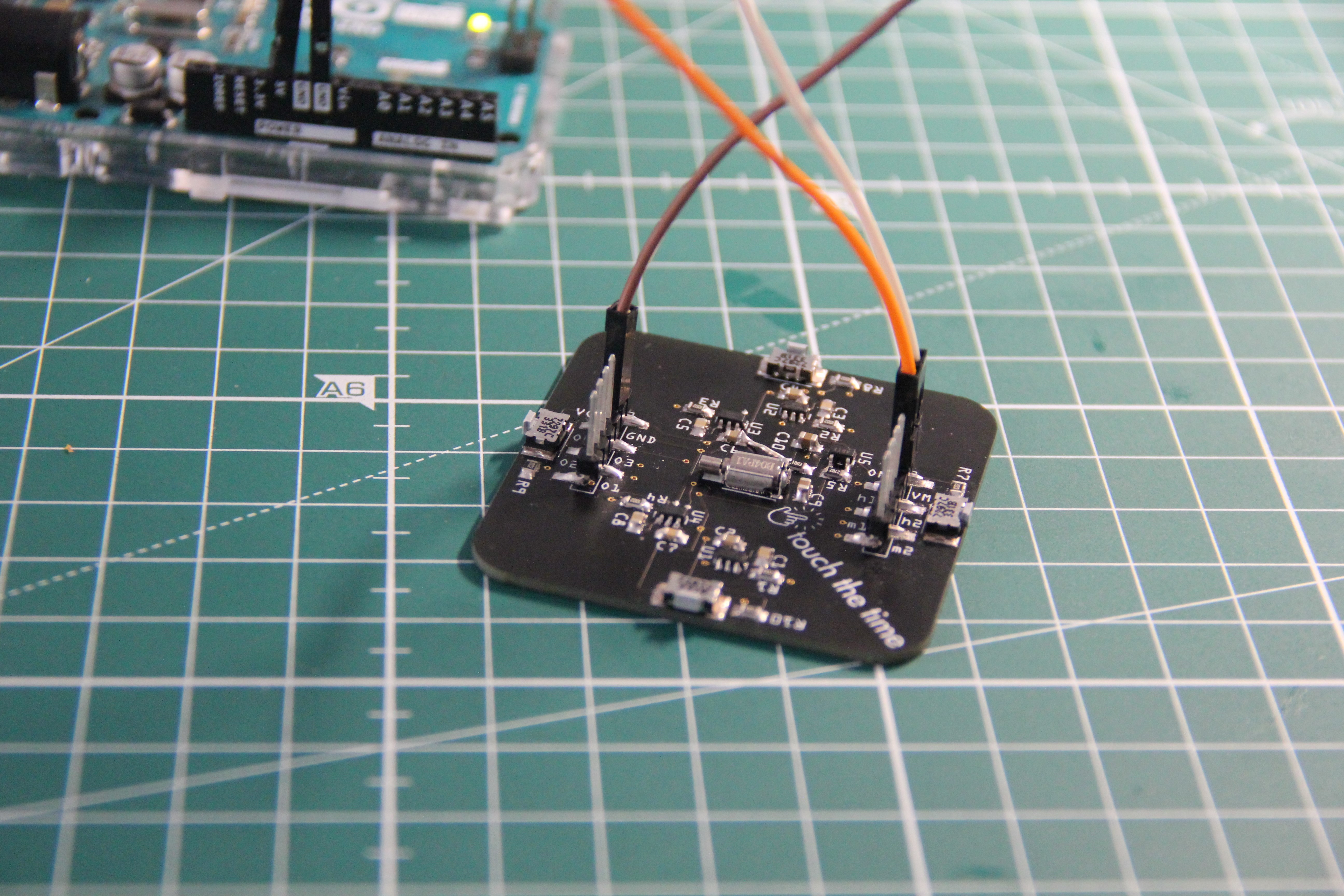
A couple of days later I got the stencil. As usual for JLCPCB completely oversized. Fortunately the stainless steel stencil can be easily cut to the desired size with a pair of scissors.Two problems occured while testing the first populated board:
- Forgot to connect GND of the pager motor driver circuitry with the main GND
- Touch sensor U4 does not work properly. I replaced the IC but the touch sensor still works not reliable. After checking the layout I think the problem could be related to a GND trace I put underneath the IC on the bottom side
![]()
 A couple of days later I got the stencil. As usual for JLCPCB completely oversized. Fortunately the stainless steel stencil can be easily cut to the desired size with a pair of scissors.