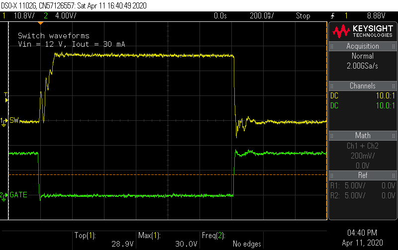
The previous update looked at voltage ripple and transients. Another important area to investigate is the switching waveforms. This shows the switch node and gate voltages.

And a close up:

The first thing to notice is that the ringing predicted by the simulation is almost nowhere as bad. Instead of rising and overshooting the off-state voltage of 22 V, it's taking a while to reach that level while ringing on the way up. This happens regardless of input voltage:


What's going on here? The snubber was expected to clamp the switch node voltage to 32 V, but the voltage never gets close. Before investigating further, it's worth commenting on the gate waveform. I added a 0 Ω series jumper in the design as an option to damp any ringing at the gate. The BSC059N04LS6 datasheets puts the Vgs(th) figure at 2.3 V max, so even at 5 V input, the switch is squarely on, and it seems the waveform is clean enough not to require additional series resistance at the gate.
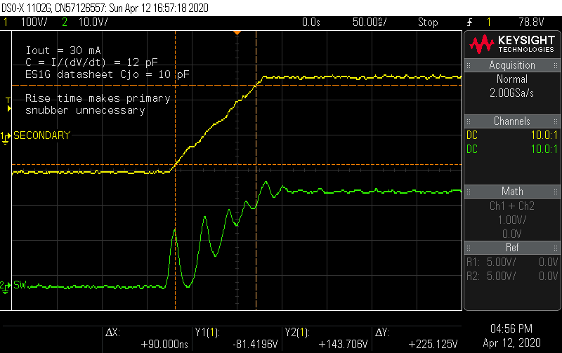
Back to the weird rising waveform at the switch node. Probing the secondary side reveals a clue.

The secondary voltage ramps as if a current source is charging a capacitor, which happens to be the real junction capacitance of the diode, closely matching the datasheet value. The ringing at the switch node has to follow this voltage ramp, so the ringing starts from a lower amplitude and decays before the switch node voltage reaches the full off-state value. Here is the first big departure from the simulation: it appears the diode model for the ES1G doesn't accurately model the junction capacitance. When I re-ran the simulation, it predicted a diode rise time of less than 25 ns.
As a side-effect, the primary side RCD snubber is not really helping anything. The voltage across the snubber capacitor remains about 16 - 17 V, so I removed it and found no change in power consumption.
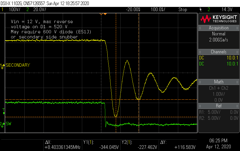
The simulation also predicts an oscillation at the secondary when the diode turns off, which is confirmed on the oscilloscope.

With the other side of the diode at 170 V, the diode sees reverse bias spikes of nearly 520 V. This ES1G diode has a VRRM (maximum repetitive reverse voltage) of 400 V, so this ringing is probably going to reduce the service life of this diode. There are a few options to correct this situation: place a higher-rated diode (such as the 600 V ES1J), add a snubber across the diode, or try a different diode with better reverse recovery characteristics.
How much will a snubber help, and what will it cost? To experiment with a snubber, I first measured the frequency of the oscillation. The resonance exists between the transformer's leakage inductance as seen on the secondary side, and the parasitic capacitance of the diode junction as it goes through reverse recovery.
 The primary side leakage inductance of the DA2032 is 150 nH, so it will n^2 * 150 nH or 15 µH on the secondary side. At an oscillation frequency of 8.4 MHz, the capacitance for this resonance is 24 pF, and the characteristic impedance (sqrt(L/C)) is 792 Ω. An RC snubber design trial should start with this resistance and a capacitance of 4 - 10x the parasitic capacitance.
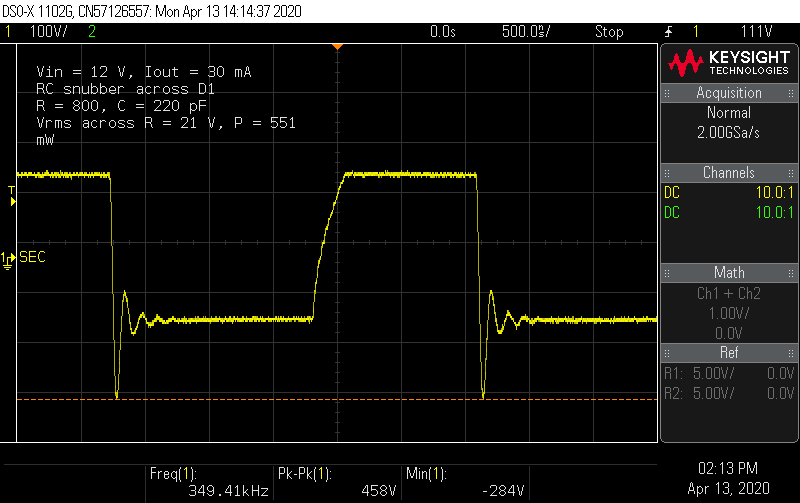
I have some assorted 250 V 0603 caps in the 100-1000 pF range, so I bodged on two in series to withstand 500 V. A 0603 820 Ω resistor exploded instantly. A single 1/4 W through-hole resistor also started smoking with a second. Substantial power was being burned off in this snubber. Finally I tried a fixture of four 1/4 W 3.2 kΩ resistors soldered in parallel, and even then, the paint on the resistors began to discolor within a few minutes. This wasn't looking promising, but I took some measurements nonetheless.

The snubber has reduced the reverse bias spike to under 460 V, but at a dear cost. Measuring the AC voltage across the resistor network showed it was dissipating over 1/2 W. That's going to wreck the efficiency of the converter, and for what? A higher-rated diode is still needed.
Dissapointed, I removed the bodged-on snubber, and ordered a few pieces of the ES1J and another diode I found, the VS-3EMH06. This diode is a "hyper-fast" rectifier (evidently the ranking is standard, fast, ultra-fast, super-fast, hyper-fast ... real helpful) with also a "soft recovery", so I'm curious to see how it will perform. There are even faster diodes out there in this lineup, but they are rated for higher current, are more expensive, and use a larger footprint. There are not a great many diodes that are designed for modest forward current, high reverse voltage, and highest speed. I'll see how this diode performs in the next update.
 James Wilson
Discussions
Become a Hackaday.io Member
Create an account to leave a comment. Already have an account? Log In.