 Evgeny
-
1Piezo triggers
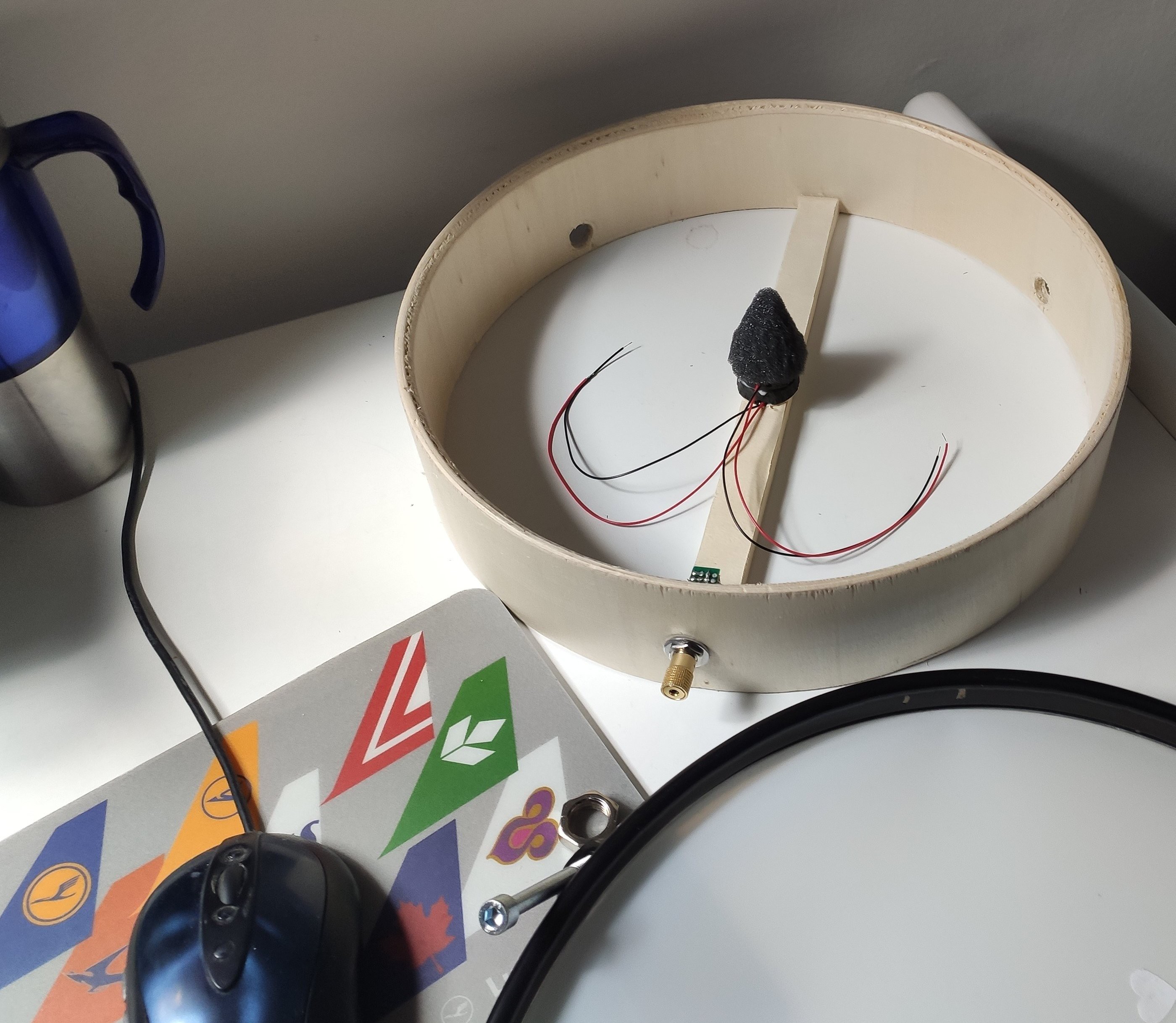
There are so many different design of triggers in the internet but... Vast majority of them do not really look like a thoughtful solution or something reliable.Initially, I started with a classical design of a foam cone in a center:
![]()
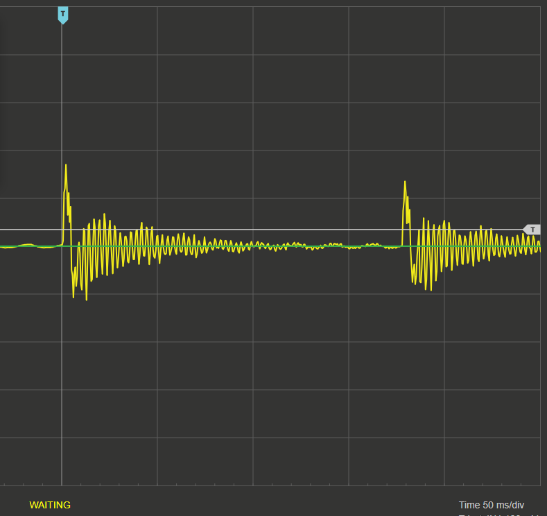
But there are two problems with that: A - very poor isolation from the shell and B - mesh vibrations are huge. The later is nice if the drum is acoustic and all, but with electronic module, all this vibration are hard to filter. This is a typical signal from piezo like on the picture above (with mesh on):
![]()
There are around 100-150ms of oscillations, and if second hit arrives in this period, it is not going to be as much reliable as one would prefer.
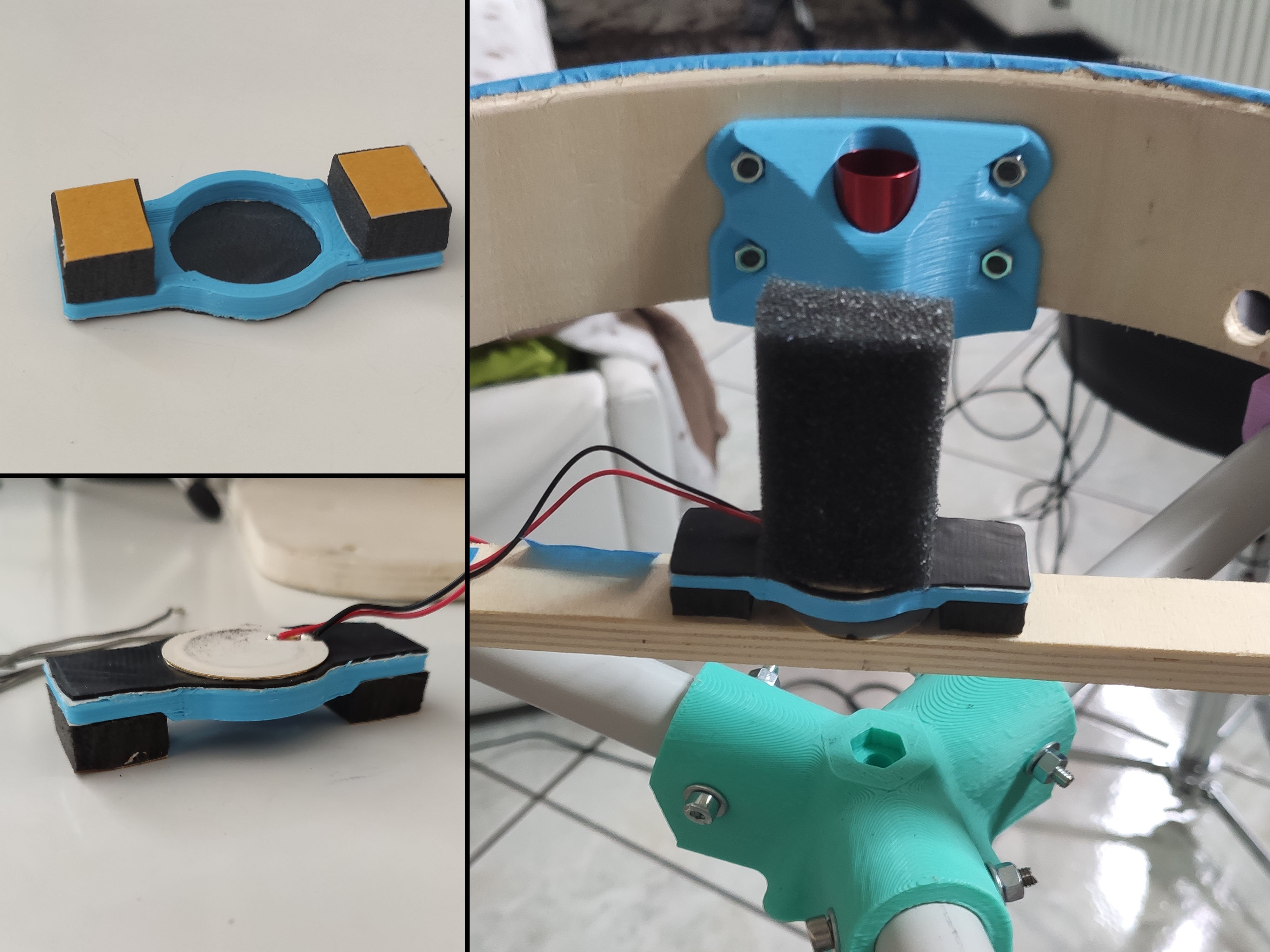
So here is my attempt to make it better. Fist, no cone. Just a ugly shaped foam brick between mesh and piezo, and complicated support for that piezo:
![]()
The trigger consists of: two pegs made of dense 8mm polyurethane foam, 3mm thick plastic plank with circular hole in the middle (dia is 2mm smaller then piezo), layer of rubber (from bicycle tube), 27mm piezo (robust one, I think murata), and a brick made of soft foam. The top of the foam extends about 1-2mm above the drum shell. Everything is connected together with double side tape.
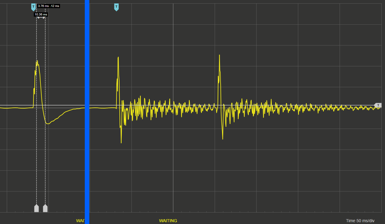
Here how the signal looks like (1 peak - mesh not installed yet, 2 and 3 - with mesh):
![]()
there is still bunch of oscillations, but considerably less than before, and the main peaks are much more pronounced.
The plastic piece can be downloaded here: https://www.thingiverse.com/thing:4315796
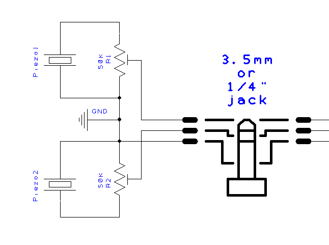
Finally, the front end electronics for the trigger consists of single trimmer (50-100 kOhm) connected like this:
![]()
This part depends a lot on electronic module, the shown solution works well for the modified DM6 module by Alesis.
-
2Mesh pads
The pads are based on toy drums which already have most of the needed bits (like rims and screws) and what missing, I 3D printed.
List of main steps:
- Preparing shells
- Trigger and "electronics" (see another instruction)
- Rim "mufflers"
- 3D printed parts
- Final assembly
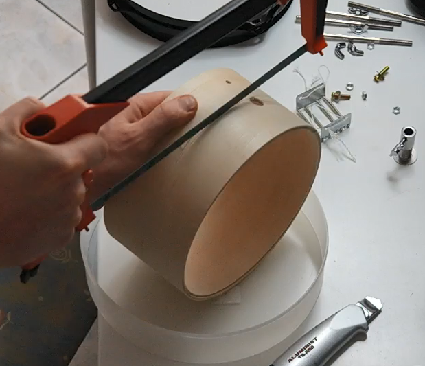
1. Preparing shells
Original 8" toy drums were 4" height so I split it into two nice 2"x8" shells. Old school way:
![]()
Same way, I prepared two plywood bars 20x190mm (10mm thick). Good thing about plywood, if you have a nice cutter, like on the photo, you can use it on instead of a saw.
There is a bunch of holes in the original shells, but they do not create any problems as far as I can tell.
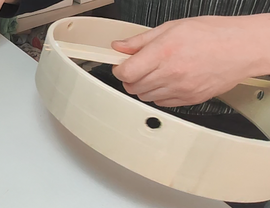
So these bars are installed on the bottom part of the shells and hold the drum trigger. I attached them using glue and toothpicks (drilling 2mm holes for them first):
![]()
Repeat 5 times and it concludes the "woodwork" part.
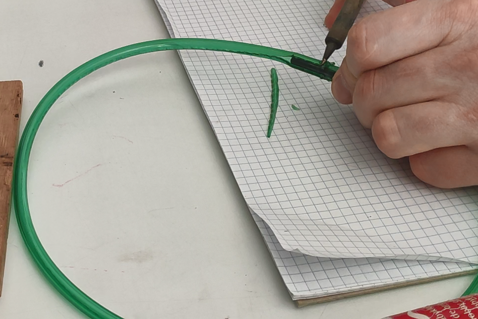
3. Rim "mufflers"Rim mufflers are basically some rubber material on the edge of a rim. From limited selection of raw materials in my house, I found out that 6mm silicone tube works pretty well.
I split cut it along and then used soldering iron (380C) to glue them together (putting 4mm drilling bit inside). Not my finest work, but it does the trick:
![]()
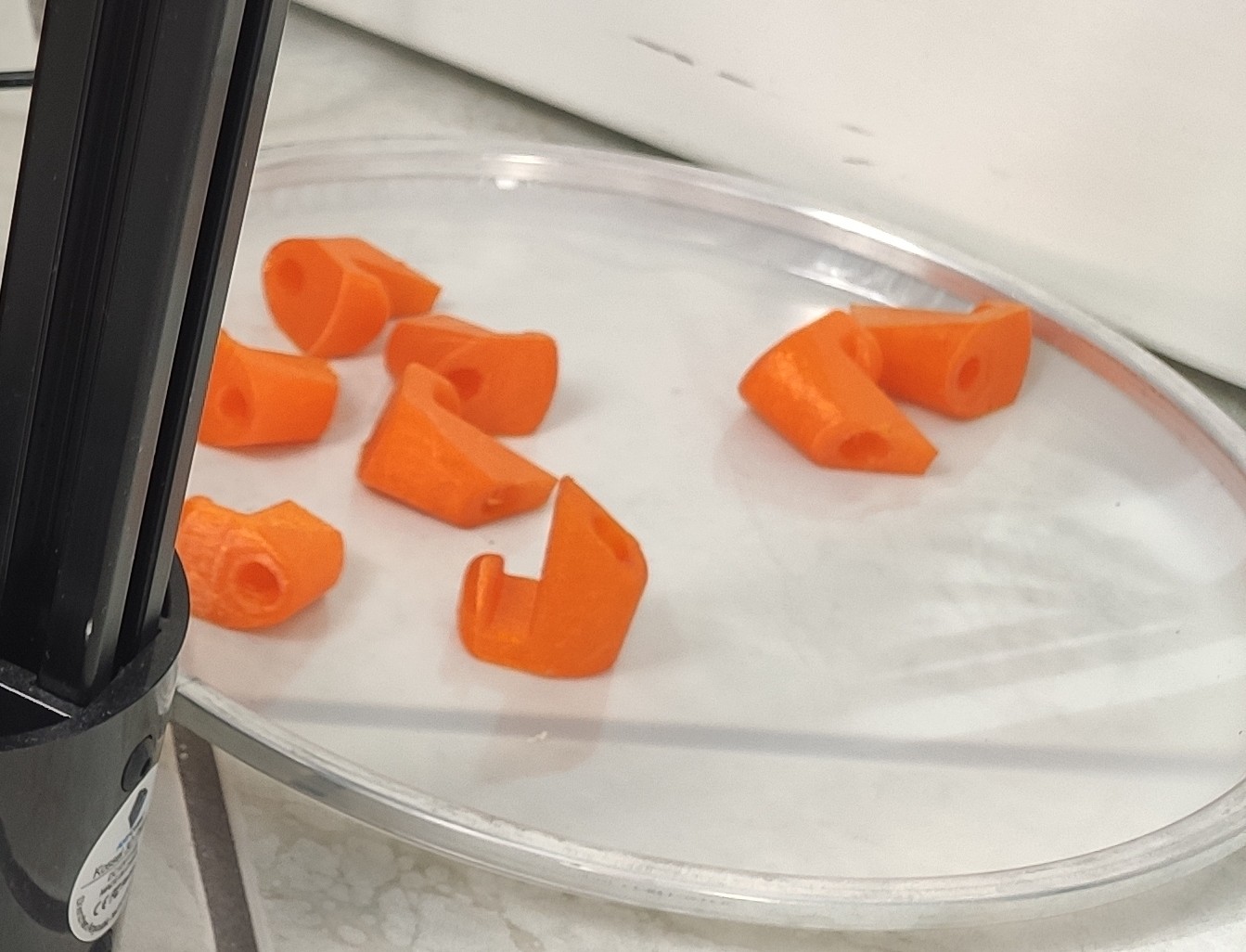
4. 3D printed parts.In order to hold everything together few custom parts are needed. Apparently 3D printed parts are strong enough to be used in drum pads so here is what I made.
(final models uploaded here: https://www.thingiverse.com/thing:4296480)
First, the hooks to attach rims to the shell (one of few designs that I tried):
![]()
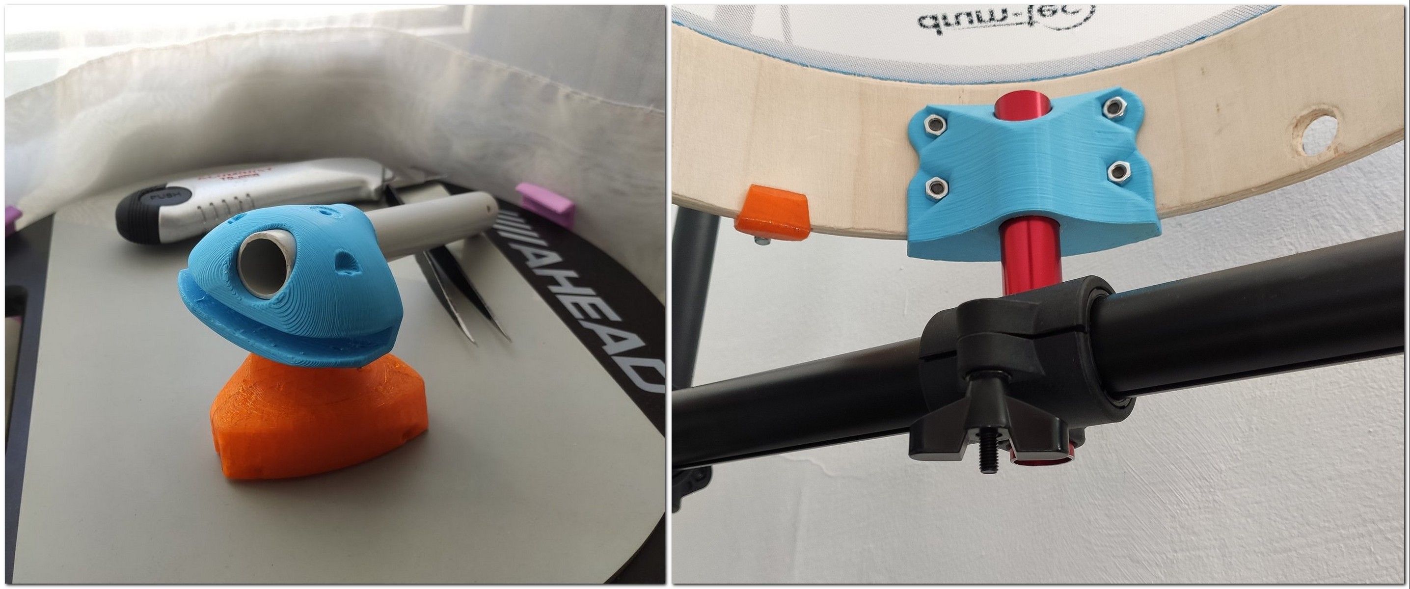
And second - rack mount. here is a bit different for the small (left) and bigger pads (right):
![]()
Small pads can be mounted without any extra fastening, whereas the 12" pads are dead fixed to the mount with 4 M4 screws.
The 20mm tubes (pvc and aluminum) are then fixed into original mounts from Alesis' pads.
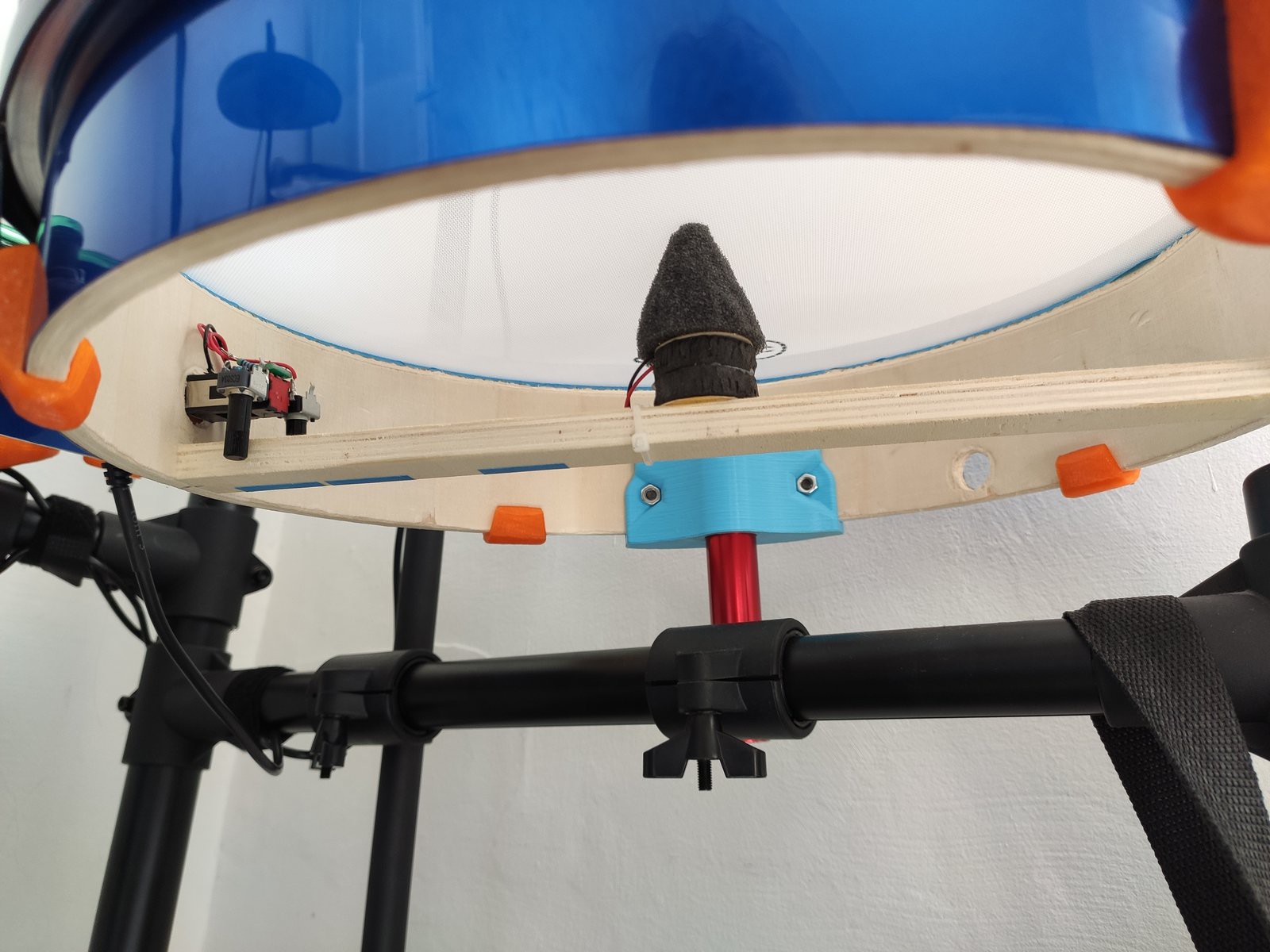
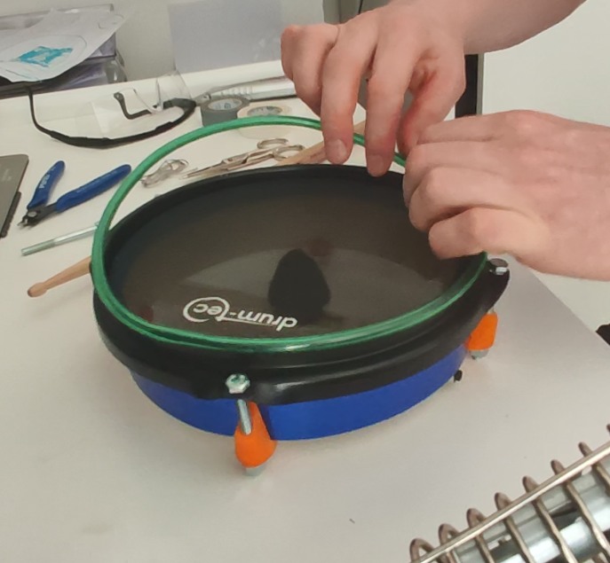
5. Final assemblyIt's pretty much obvious where all this goes, so here are some pictures of assembled pads (some with old triggers, dont mind that):
![]()
![]()
-
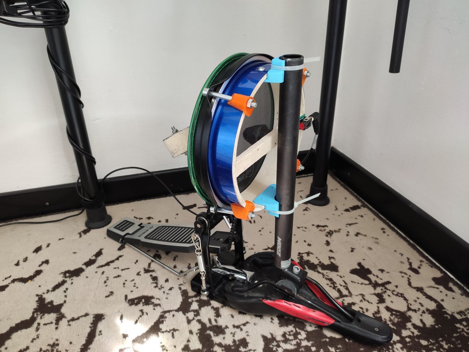
3Kick pad + pedal.
The original kit had a simple electric pedal. After few lessons I realized we will never find common language and i had to move on.
First, I have bought an inexpensive kick pedal, and then tried to ding a way to attach a trigger to it.
(final 3D models uploaded here: https://www.thingiverse.com/thing:4296480)
I have tried quite a few designs, my own and copied from internet, but in the end nothing can beat my final solution:
![]()
It a bike saddle with 27.2mm seatpost attached, and a pad fixed with a zip ties. Here is the back view:
![]()
The best part of it, this design has no problem with repeated triggering. At least loosing a bit the mesh and lowering the beater (you can see about 2cm of the rod on the photo).
And final note, the original pedal was a bit too small for me, so I decided to keep the plank from the original pedal.
-
4Getting into the electronics
So this is the most advanced part of the project. it involves lots of soldering of 0603 resistors.
So the DM6 module, with which my kit was equipped, is hardfixed to work with 1 double zone snare, 3 toms, 3 cymbals, and 2 pedals (kick can be both analog and digital). There are no setting, the only thing one can adjust is volume of each pad.
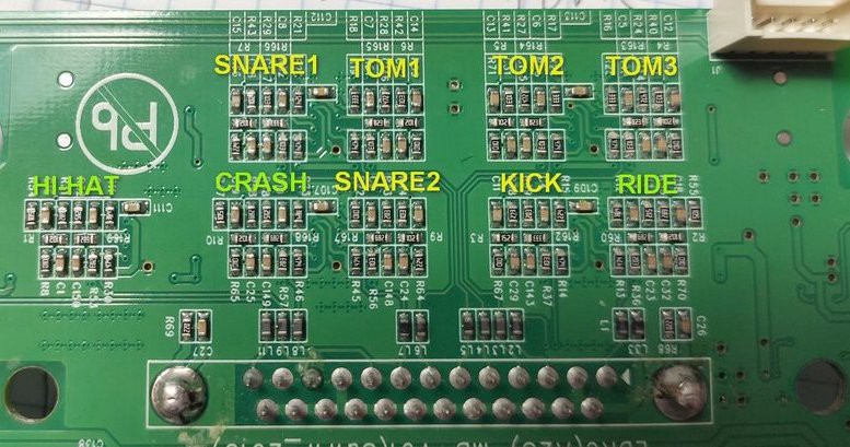
and in fact, once you open the module, you can see 9 similar sets of components,one for each analog channel:
(yellow are the one I worked with)
![]()
My guess, is that you could buy original Alesis mesh pad and they probably would work plug and-play with the drum module (or maybe not), however, considering ridiculous price policy on the e-drum market, I prefer to do it "the hard way"
Anyhow. After days trying to understand what these component do and how electronics work, I can conclude that I failed. however, it does not prevent me from getting the result. I think there is a lot of signal processing happening on the CPU level, so I do only what I can.
Long story short - the components on this side of the board are frequency filters for operational amplifiers (located on the back) (there is schematics, if some one interested). Surprisingly, it seems that all capacitors are identical in all the channels, so we get to work mostly with the resistors.
There are 4 different sets of components, according to 4 different types of pad:
- snare 1 (head)
- snare 2 (rim)
- tom 1,2,3
- kick
Snare 1 has the best sensitivity of all, and directly work with mesh pads that I made.
The final mapping of modified components:
![]()
There are few groups of components, simplified version is like this:
1. R1 - input LP filter (with cap underneath it), final value 30k for R1
2. R4+C1 and R2+R3 - feedback gain and filter, final values are not easy to calculate or simulate. Randomly varying nominal values best result acieved with these numbers:
R4 - 12K for 8" 15k for 12"
C1 - +1uF (solder another on top of original one)
R2 - 120k
R3 - 10k3. For the kick and snare2 (rim) it is still work in progress, so temporary values that gives me good results are:
R1 - 30K, R2 - 120k, R3 - 10k, R4 - 1k, R5 - 220k, R6 - 1k. C1 - +1uF
The reason that the last two pads are a work in progress is that the kick uses different trigger geometry (cone, not brick) and it has different sensitivity, and the rim has some special processing logic, and with identical values like all the rest channels it gives only 70% of dynamic range.
So that is it. Using external trimmer on the pads, I can adjust the sensitivity quite well so they all sound the way I expect.
To make easier, I used small software "pocket midi " (https://www.morson.jp/pocketmidi-webpage/) that lets you see realtime midi codes from the module, and i adjusted the trimmers on each pad to match maximum volume (very strong hit results in "7F" midi velocity).
DIY mesh conversion of a simple drum set
Pad-to-mesh conversion of an electronic drum set (Alesis DM6) using low cost toy drums


Discussions
Become a Hackaday.io Member
Create an account to leave a comment. Already have an account? Log In.