M. Bindhammer
-
Beta testers wanted
06/19/2020 at 09:00 • 11 commentsThe first
threesix who respond in the comments below will receive MI/O (including wristband, packaging and shipment) free of charge. The only condition is to write a small review here on hackaday.io. Of course it would be even cooler if you used MI/O in one of your projects.Update June 24, 2020: Will get the beta testing samples next week. After I have tested them, I will collect the addresses and send the samples.
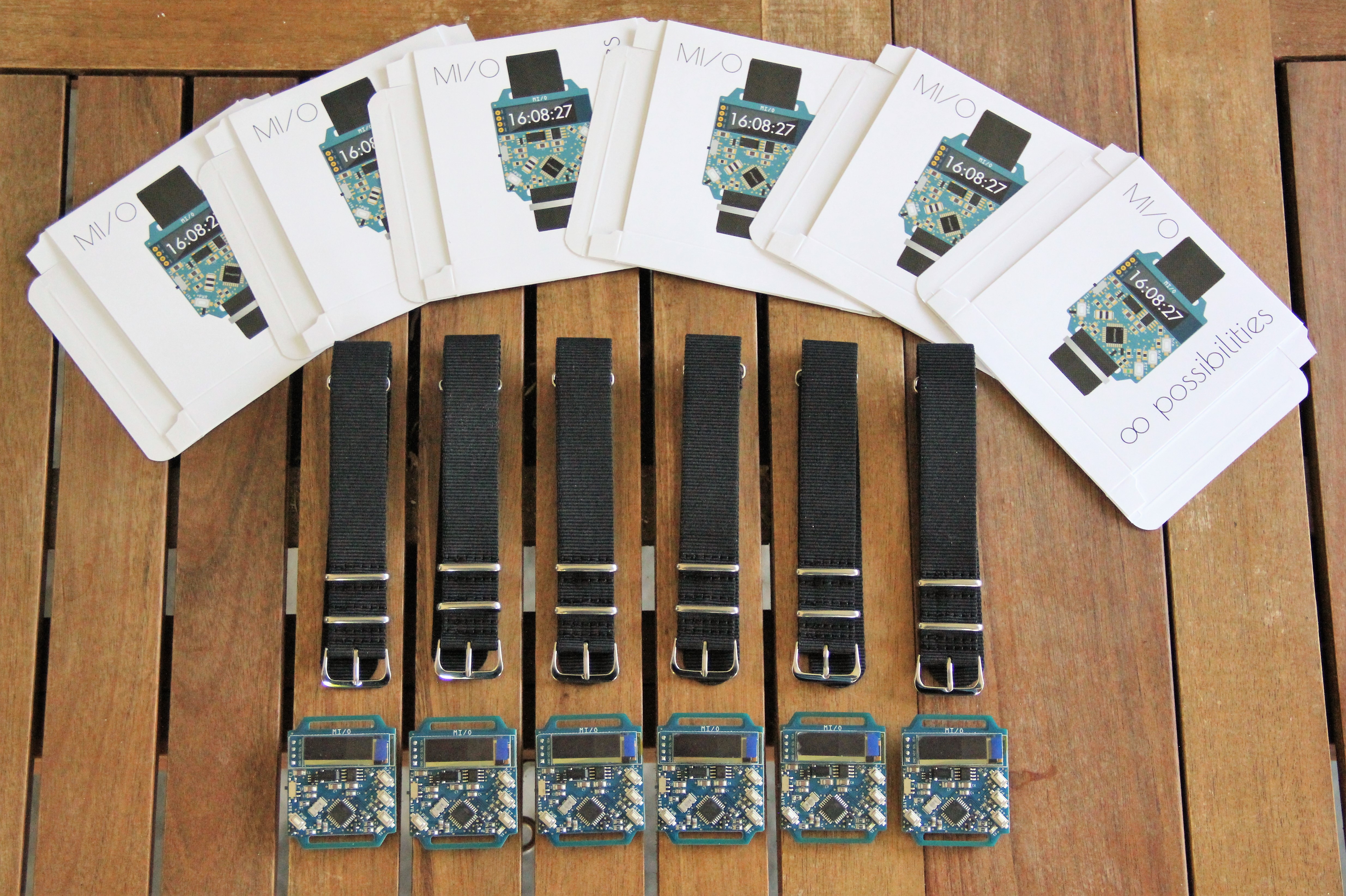
Update July 6, 2020: Beta testing samples ready for shipment...

MI/O is manufactured at makerfabs, an Open Hardware, Arduino, Raspberry Pi, mbed, BeagleBone, IoT, Smart Home, etc, Related Products & Services Vendor for Makers and new Startups. They are very cooperative, communicative, take also care of smaller orders, work very clean and fast. A big thank you to the team.
-
On Sale
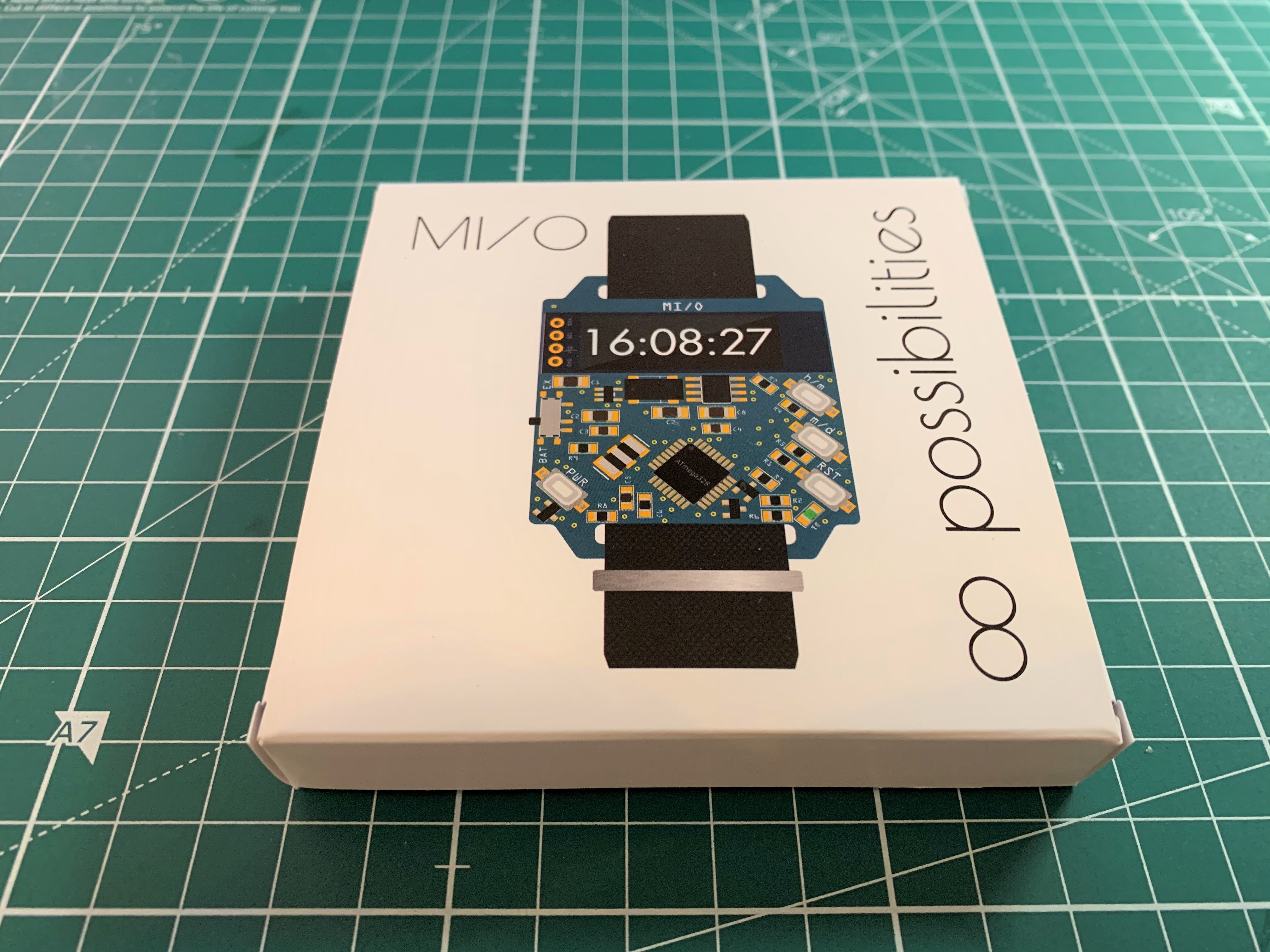
05/22/2020 at 17:10 • 0 commentsI am planning an Indiegogo campaign with MI/O. I've teamed up with makerfabs. They will assemble the wristwatch (100 pieces for now). Meanwhile I designed the packaging, a folding box 94 x 94 x 14 mm, 4-color print, glossy look, printed in Germany:
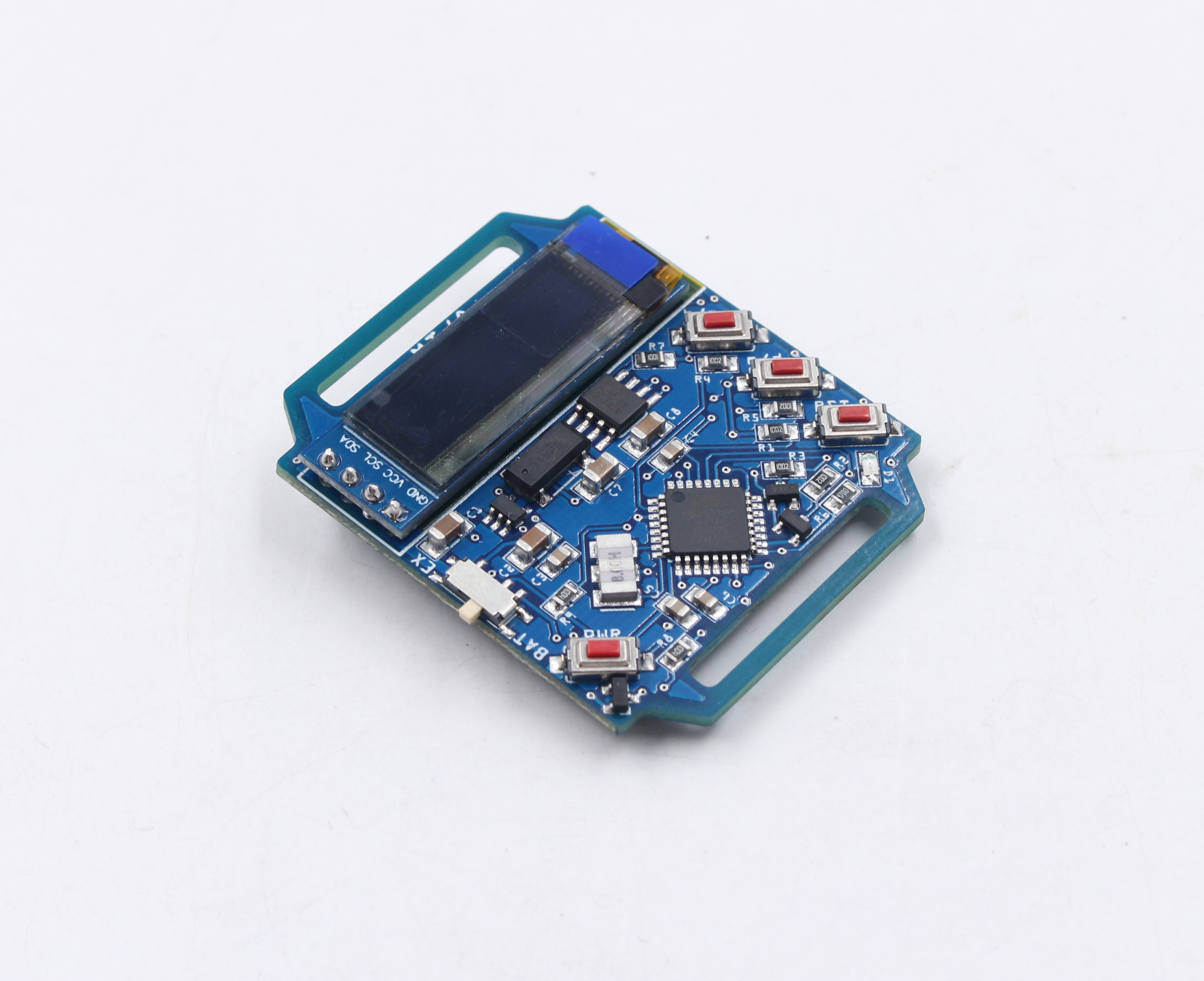
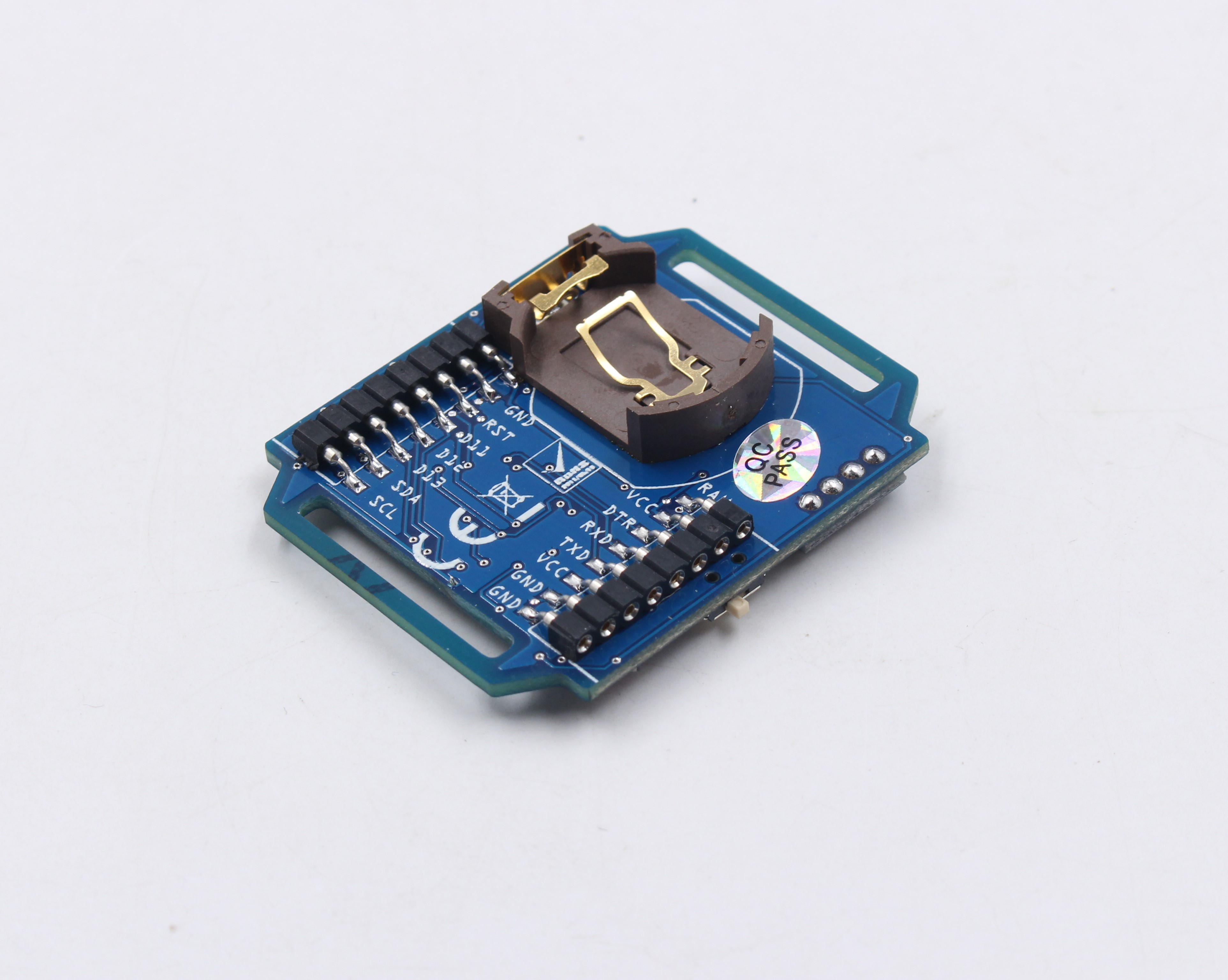
First pictures from the pre-production, but still have questions about the left offset coin cell holder:
Assembly of the OLED display during pre-production:
After some emails back and forth and a call from my wife (she is Chinese) the coin cell holder is replaced by the original one. But overall makerfabs is doing a very good job so far, you can't say anything else.
In the meantime I started the Indiegogo campaign. It is my first crowdfunding campaign ever and it took me some time to get along with Indiegogo. In the end, however, it is actually quite simple and you are guided step by step through the whole requirements. Most of the time I spent on all the graphics and the preparation of the pictures. I am running the campaign completely alone, there is no team, no CEO, CTO, co-founder, adviser and all that nonsense. I don't think the campaign will be a success, but I have learned a lot (even how to design a package) - that's the main thing.
-
Second prototype
05/02/2020 at 22:27 • 0 commentsAfter testing the first prototype a couple of days I decided to start working on a second prototype with some improvements. Biggest one: The I2C pullup resistors can now be disabled to prevent "phantom powering" of the connected devices. Means also I have to desolder the two pullup resistors on the OLED breakout before assembling it on the main board. Should provide a significant improvement of the running time when powered by a coin cell. The watch should now be operated for at least one week with a freshly charged LIR2032H coin cell. I have already discarded the idea to power the watch by a conventional 3V coin cell. The voltage is too close to the brownout detection threshold of 2.7V.
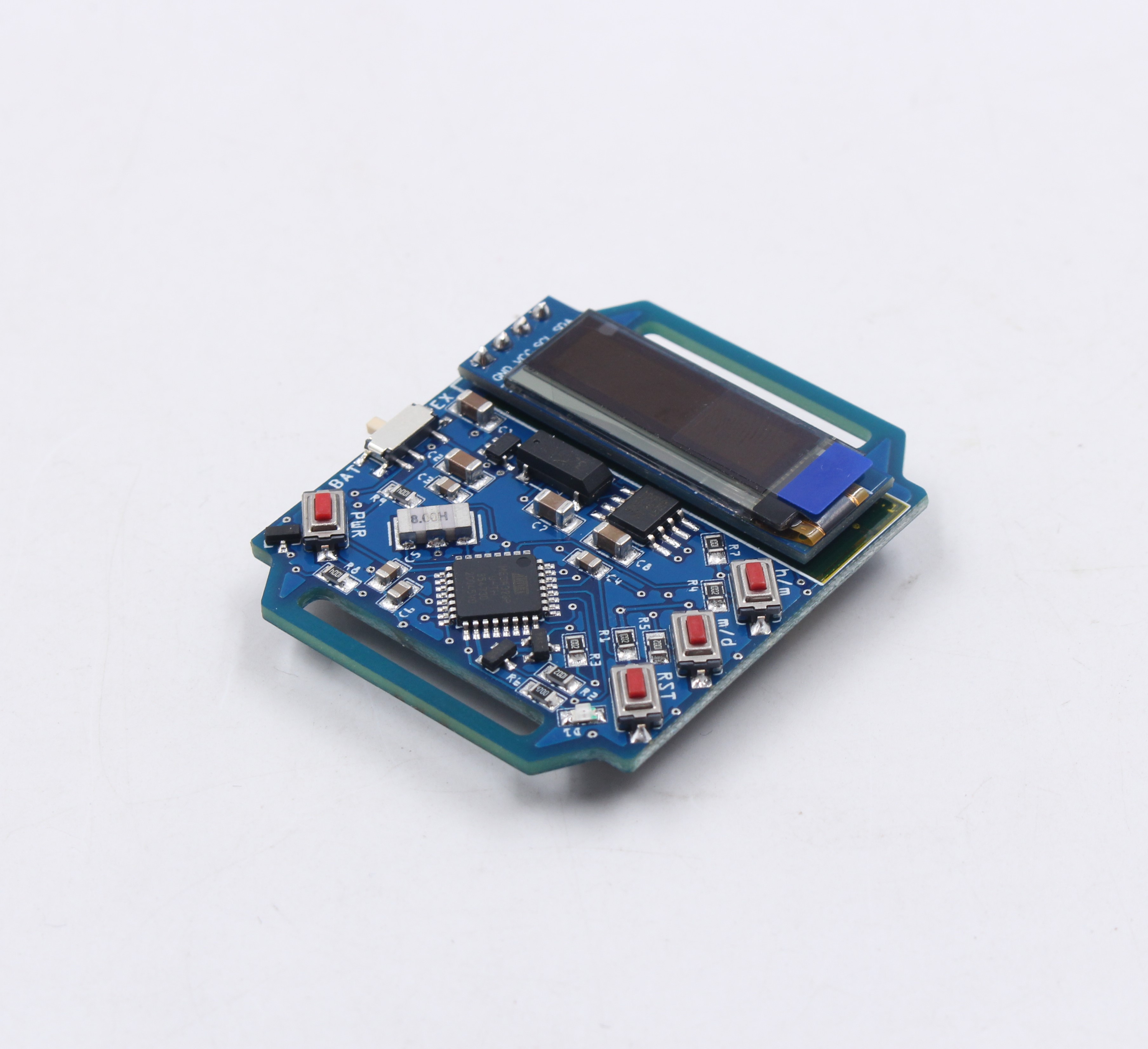
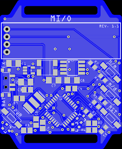
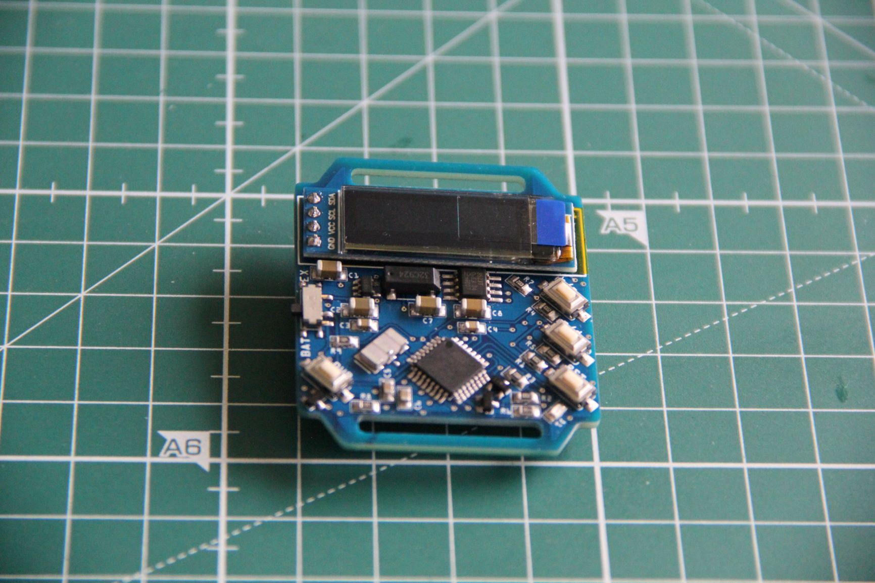
Screenshot of the top. Two SOT-23 p-channel mosfets and a resistor added:
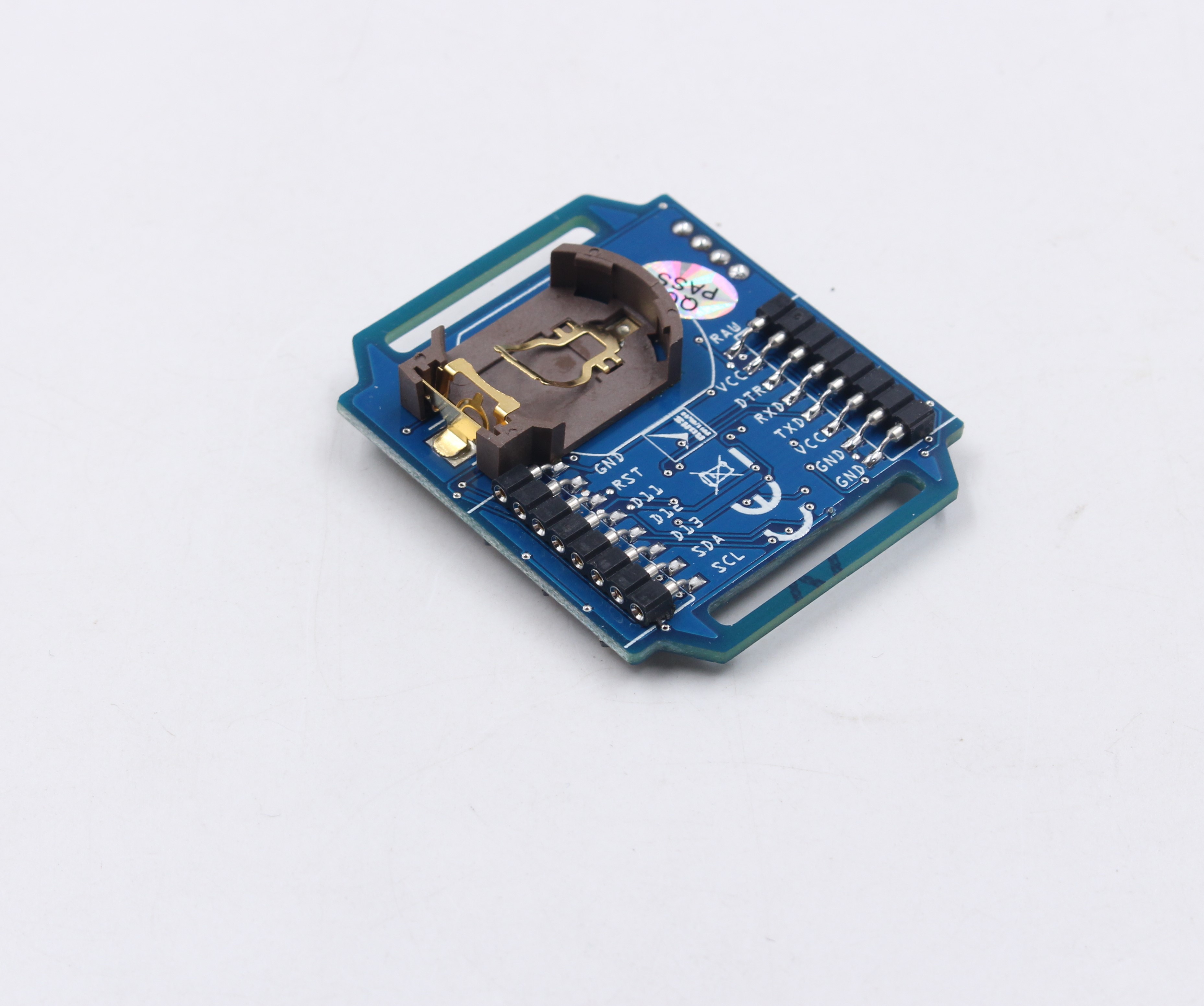
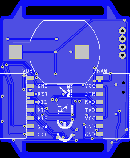
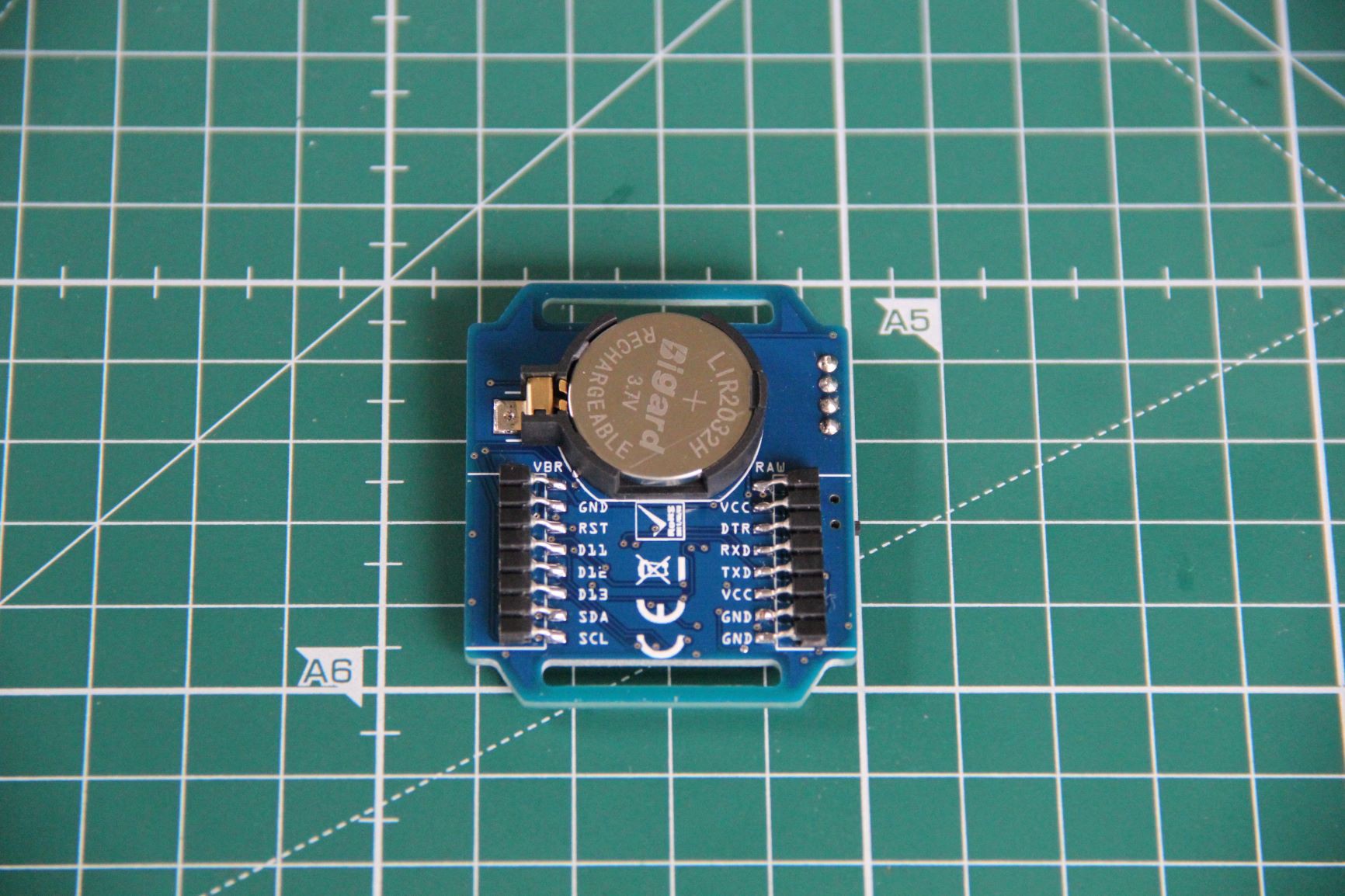
Screenshot of the bottom. Some symbols added to be able to sell the board in Europe:
As usual I used a stencil, low temperature melting soldering paste and a hot air gun to populate the board. Some soldering was done directly with a soldering iron. I am very satisfied with the result, looks like machine made:I replaced the normal female pin headers on the backside by 2.54mm machine pin female headers - single row, 1 x 8, round pin, H3.0, L7.4 - horizontal, SMT, as they have less mounting height respectively length and are more precise.
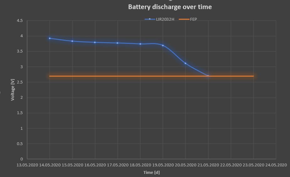
Below you can see the discharge curve over time of a freshly charged LIR2032H coin cell. FEP (Functional End Point) is reached at 2.7V when BOD (Brown-Out Detection) threshold is reached. Possibly further improvements can be achieved via software, for example putting the ATmega 328P into sleep mode (not done yet).
Other than mentioned in the data sheet, it still seems possible to set the brownout detection threshold to 1.8V. To do this, proceed as follows.
First we have to modify the boards.txt file. This file can be usually found in folder C:\Program Files (x86)\Arduino\hardware\arduino\avr. Open the boards.txt file, search for the section where the different Arduino Pro Mini boards/processors are defined and copy/paste the following block as a new definition of an Arduino Pro Mini into the section of the boards.txt file.
## Arduino Pro or Pro Mini (3.3V, 8 MHz) w/ ATmega328 BOD at 1.8V
## --------------------------------------------------
pro.menu.cpu.8MHzatmega328bod1v8=ATmega328 (3.3V, 8 MHz, 1V8 BOD)

pro.menu.cpu.8MHzatmega328bod1v8.upload.maximum_size=30720
pro.menu.cpu.8MHzatmega328bod1v8.upload.maximum_data_size=2048
pro.menu.cpu.8MHzatmega328bod1v8.upload.speed=57600

pro.menu.cpu.8MHzatmega328bod1v8.bootloader.low_fuses=0xFF
pro.menu.cpu.8MHzatmega328bod1v8.bootloader.high_fuses=0xDA
pro.menu.cpu.8MHzatmega328bod1v8.bootloader.extended_fuses=0x06
pro.menu.cpu.8MHzatmega328bod1v8.bootloader.file=atmega/ATmegaBOOT_168_atmega328_pro_8MHz.hex

pro.menu.cpu.8MHzatmega328bod1v8.build.mcu=atmega328p
pro.menu.cpu.8MHzatmega328bod1v8.build.f_cpu=8000000L
Save the boards.txt file at the same location and close it.
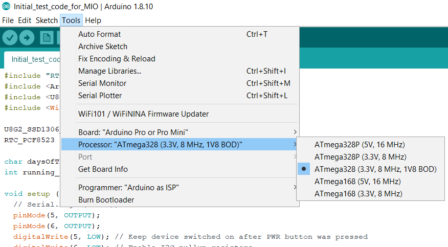
Re-start the Arduino IDE. Go to Tools. Choose Board: "Arduino Pro or Pro Mini", Processor: "ATmega328 (3.3V, 8 MHz, 1V8 BOD)" and Programmer: "Arduino as ISP".
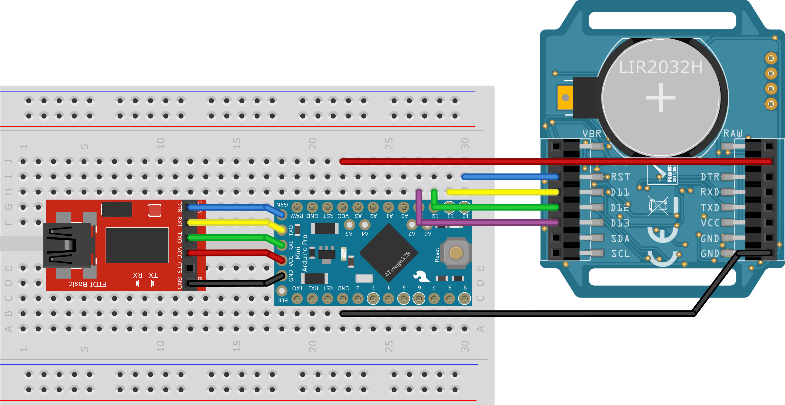
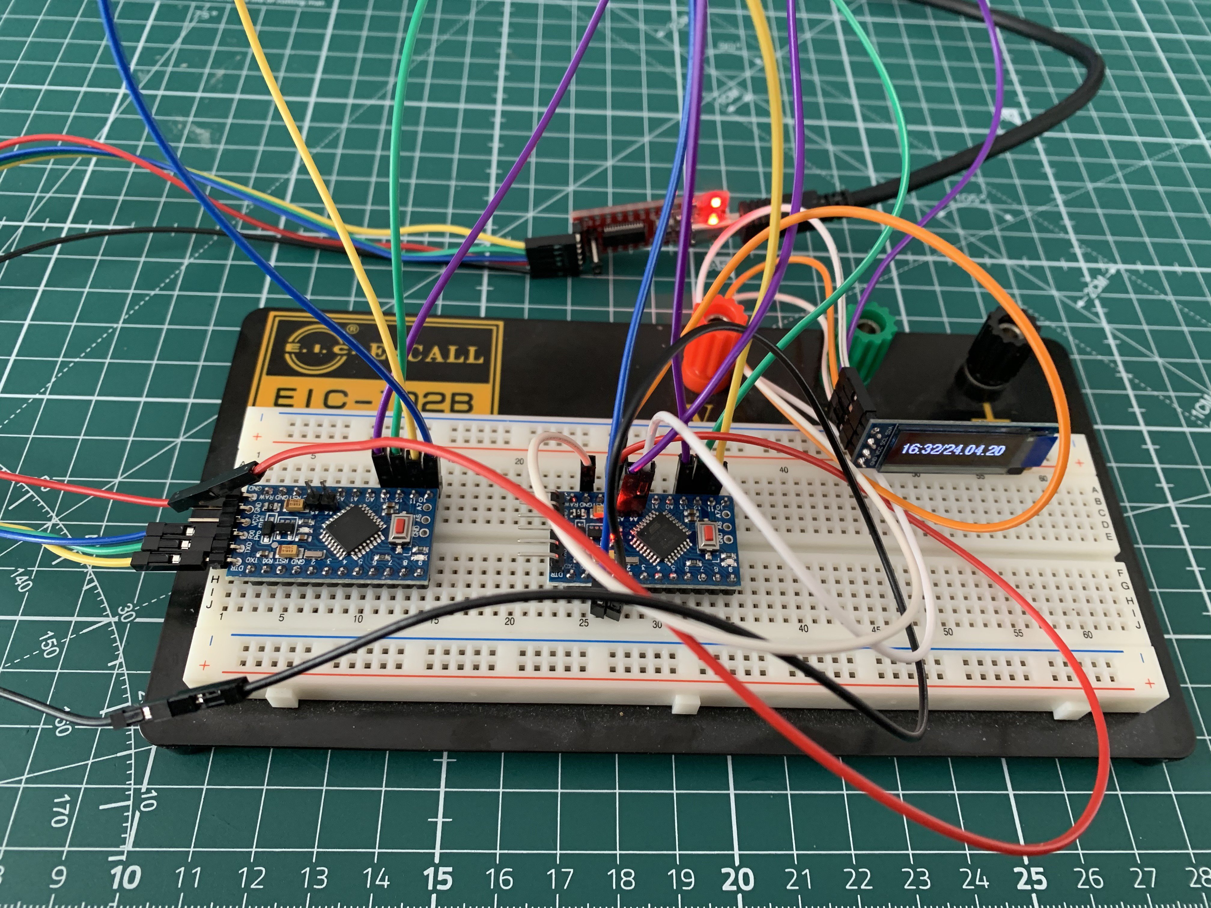
To burn the bootloader and thus set the extended fuses from default 2.7V down to 1.8V, an Arduino Pro Mini (or clone) is required as a programmer and a 3.3V FTDI in addition to the MI/O board. These are wired as shown below:
Once everything is connected (don't forget to set the switch on the MI/O board to external power supply) hit Burn Bootloader. This warning may appear:
avrdude: WARNING: invalid value for unused bits in fuse "efuse", should be set to 1 according to datasheet
This behaviour is deprecated and will result in an error in future version
You probably want to use 0xFE instead of 0x06 (double check with your datasheet first).
In this case open boards.txt file again and replace 0x06 with 0xFE at the appropriate position, save, restart Arduino IDE and repeat Burn Boatloader with the already mentioned settings. 0x06 = 0000 0110 and 0xfe = 1111 1110 but unused fuse bits often read back as 1 and the extended fuses only use the lower 3 bits, so FE will be just fine in place of 06.
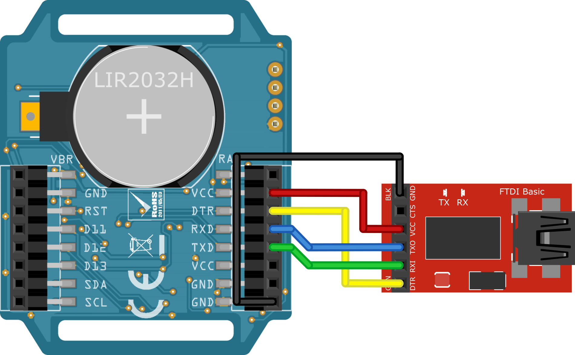
The MI/O board is now also able to be powered by a 3V CR2032. By the way, with bootloader MI/O can be programmed directly via FTDI:
After I bought a multimter with much better resolution, I was finally able to measure the exact power consumptions:
Power consumption standby:
- 2 µA @ 3 V (power switch at EX position)
- 38.5 µA @ 3 V (power switch at BATT position)
- 2.7 µA @ 3.7 V (power switch at EX position)
- 330 µA @ 3.7 V (power switch at BATT position)
Power consumption during time and date reading:
- 10 mA @ 3 V (power switch at BATT position)
- 12 mA @ 3.7 V (power switch at BATT position)
-
Designing and building add-ons
04/30/2020 at 16:07 • 0 comments1. USB power supply and a reading light
USB power supply add-on gerber rendering:
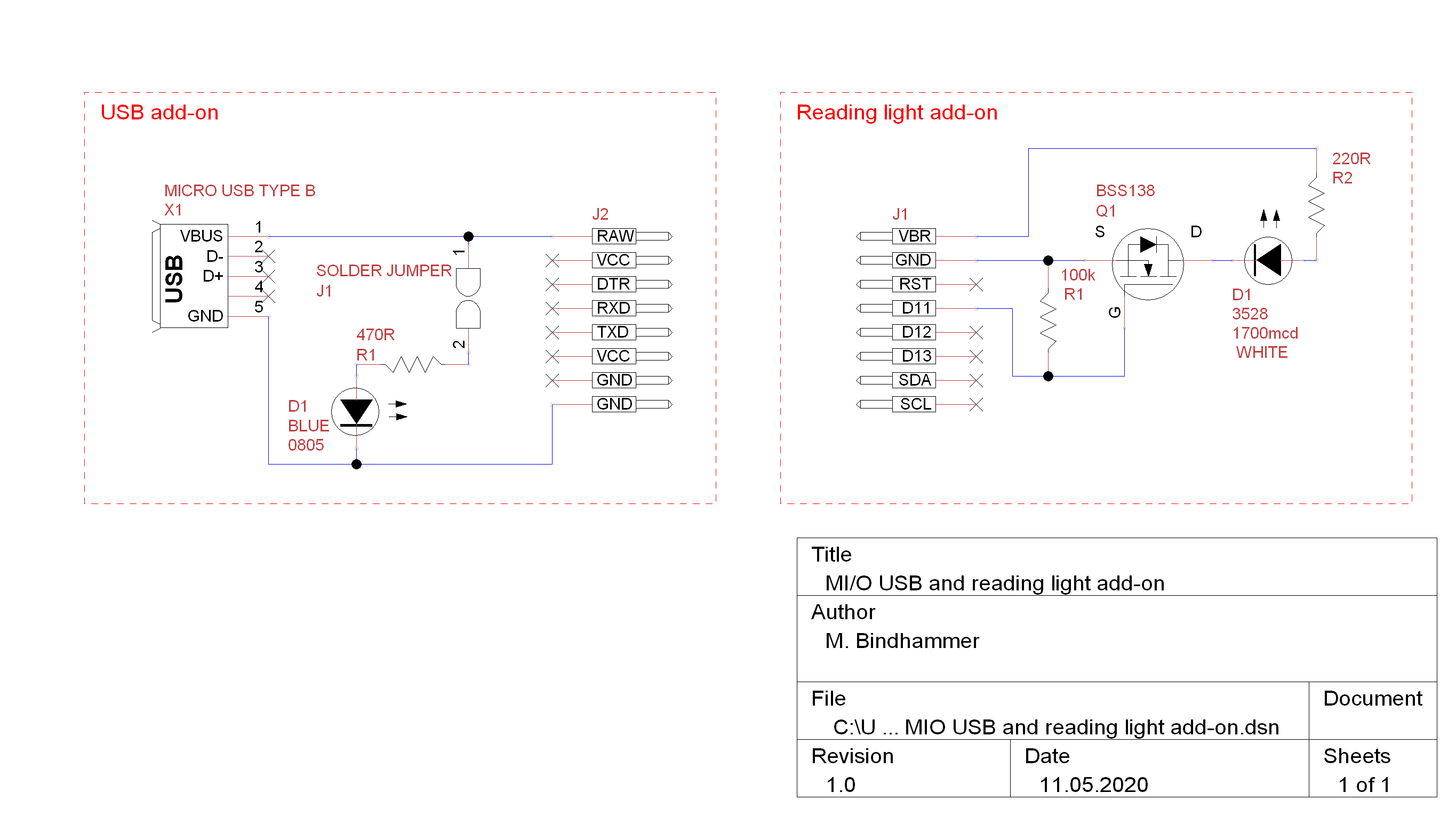
I added two additional solder pads (power isolation jumper) to enable the power indicator LED. Some may need it, some not.
Reading light add-on gerber rendering:
The LED (PLCC2 package) can be dimmed by PWM and controlled by the watch (e.g. switched on at 18:00 and switched off at 20:00).
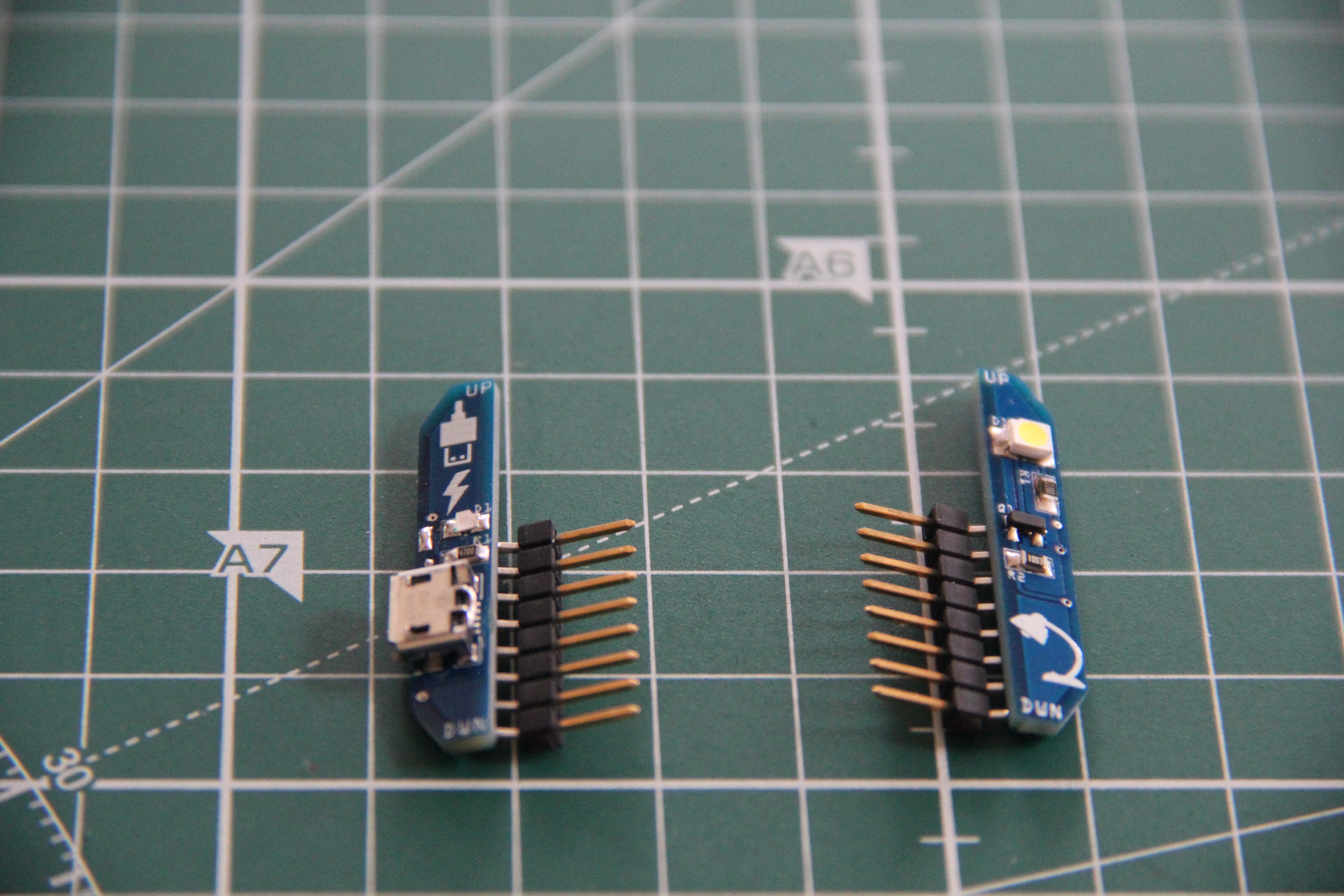
Populated and tested add-ons:
The connectors are male headers, 8-pin, SMD, 2.54mm, right angle.
Schematic:
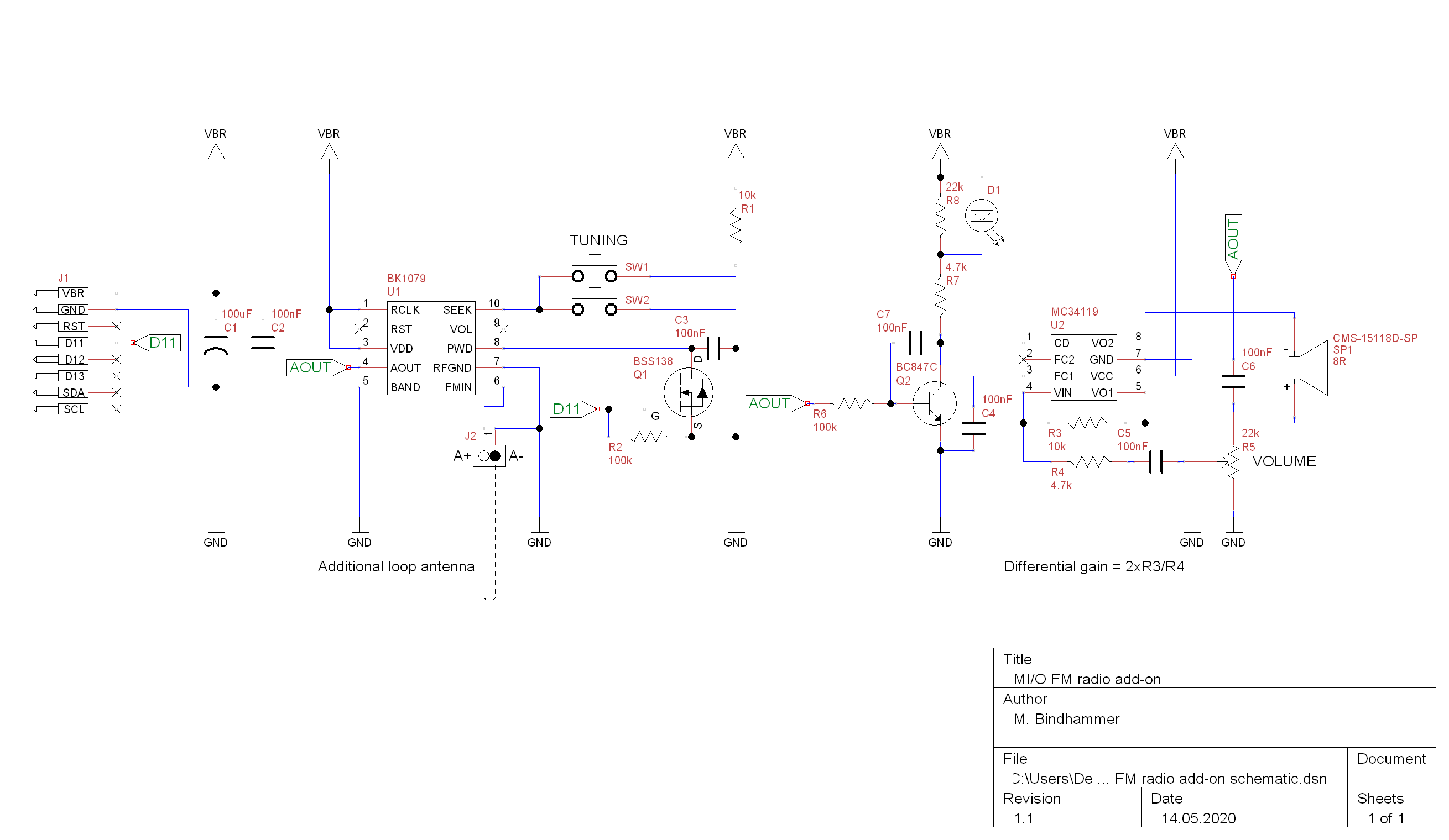
2. FM radio
The FM radio is based on the receiver IC BK1079. The antenna signal is boosted in the analog part of the internal circuit by a highly sensitive amplifier (LNA, Low Noise Amplifier), whereas a regulated amplifier (PGA, Programmable Gain Amplifier) reduces the gain when the signal is too strong. The Analog-to-Digital Converter (ADC) converts the signal into a sequence of numbers, which is then processed digitally. The processing is done by a digital signal processor. It filters and demodulates the frequency-modulated signal and filters the audio signal so that only the audio frequency range is provided. It also controls the Automatic Gain Control (AGC) to prevent overmodulation. The processed signal is sent to the Digital-to-Analog Converter (DAC), which converts it into an audio signal. The finished radio signal is then available at the analog output AOUT. The digital tuning contains a microcontroller that controls the search and other functions. It uses a PLL (Phase Locked Loop) to precisely tune a high frequency oscillator that determines the receiving frequency. The PLL can be operated either digitally with a connected crystal (DPLL) or analog (APLL). An internal voltage regulator ensures a stable internal operating voltage even if the battery voltage is varying.
The complete schematic of the FM radio add-on is shown below. The audio signal is amplified by the low power audio amplifier MC34119. Volume is adjusted via the potentiometer R5, the radio can be tuned via the two tactile switches SW1 and SW2. When the gate of the n-channel MOSFET Q1 is put to a HIGH state, the MOSFET pulls the PWD pin of U1 to GND, and the BK1079 goes into power down mode. When the BK1079 is active, an average DC voltage appears at the analogue output (AOUT) together with the AF signal. This is used to switch the LED D1 on and to enable the amplifier U2 via the npn transistor Q2. In the power down state U1 switches this DC voltage off. The transistor Q2 turns off, the LED too and the amplifier is driven into power down state via its chip-disable input.
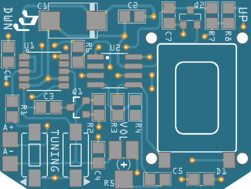
The SMD speaker is very small, just 11 x 15 x 3mm; I think it is used in smart phones. I put 4 holes around the land pattern of the speaker to have the possibility to mount a 3-D printed enclosure to improve the sound of the speaker if necessary.
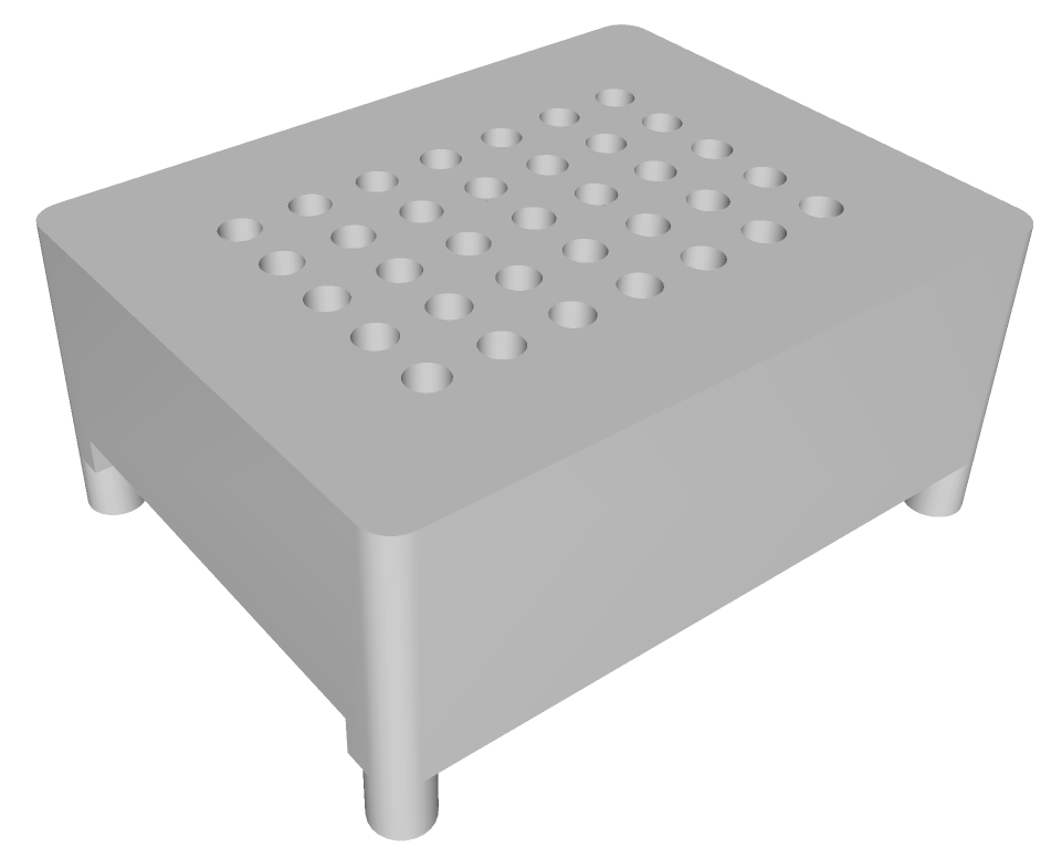
3-D model of the speaker enclosure. As a reference I used Best Practices for Designing Micro Speaker Enclosures.
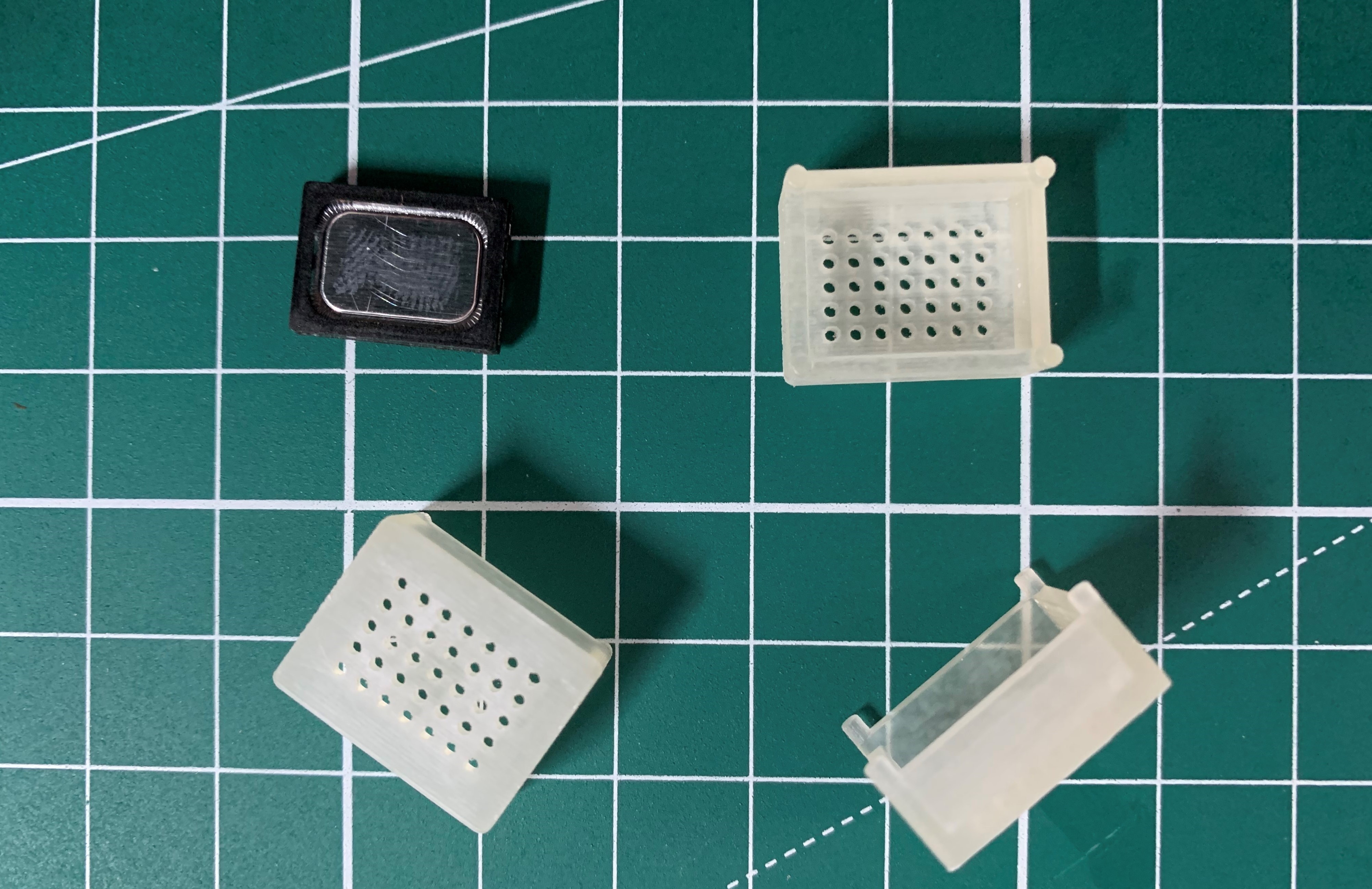
3-D printed speaker enclosure and speaker:
Enclosure was printed by Shapeways, using Fine Detail Plastic setting.
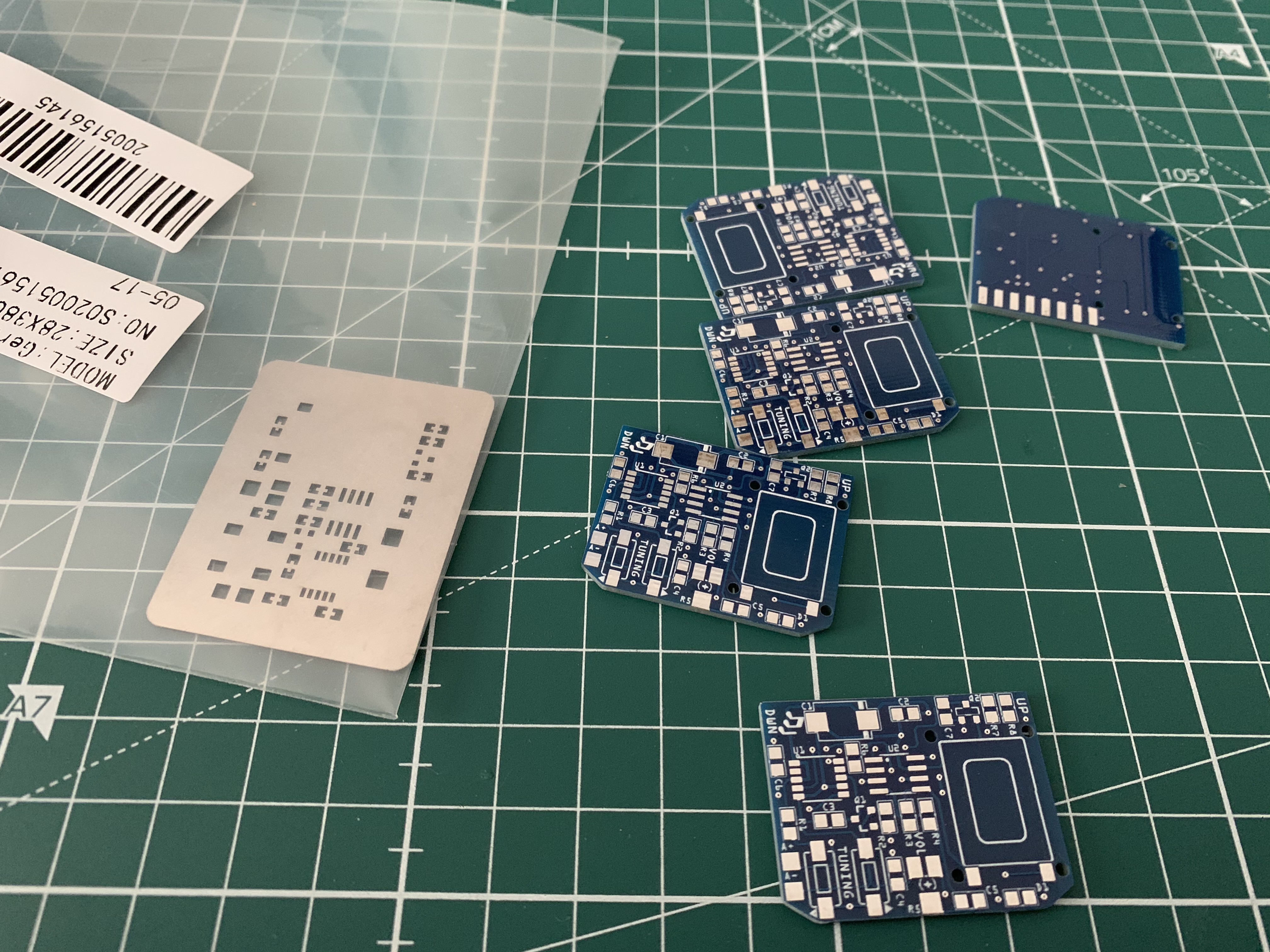
The standard 5 PCBs and custom cut stainless steel stencil from JLCPCB:
USB power supply, watch and finished FM radio add-on in use. An antenna with a length of 20 cm delivers crystal-clear reception.
3. Watering system for indoor plants
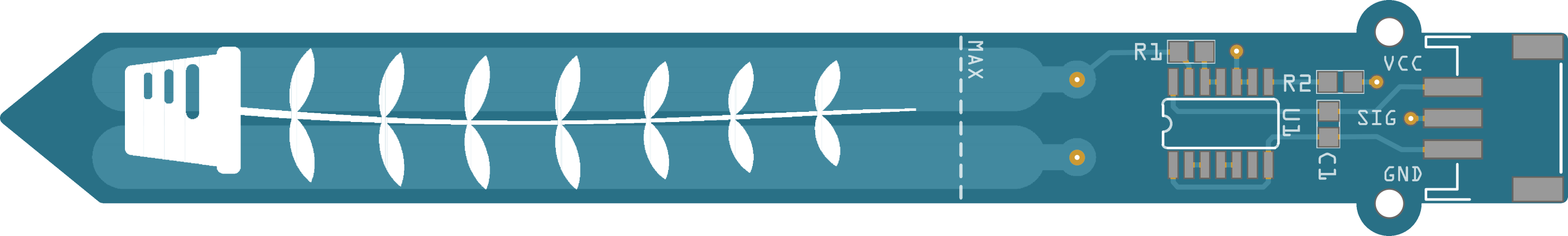
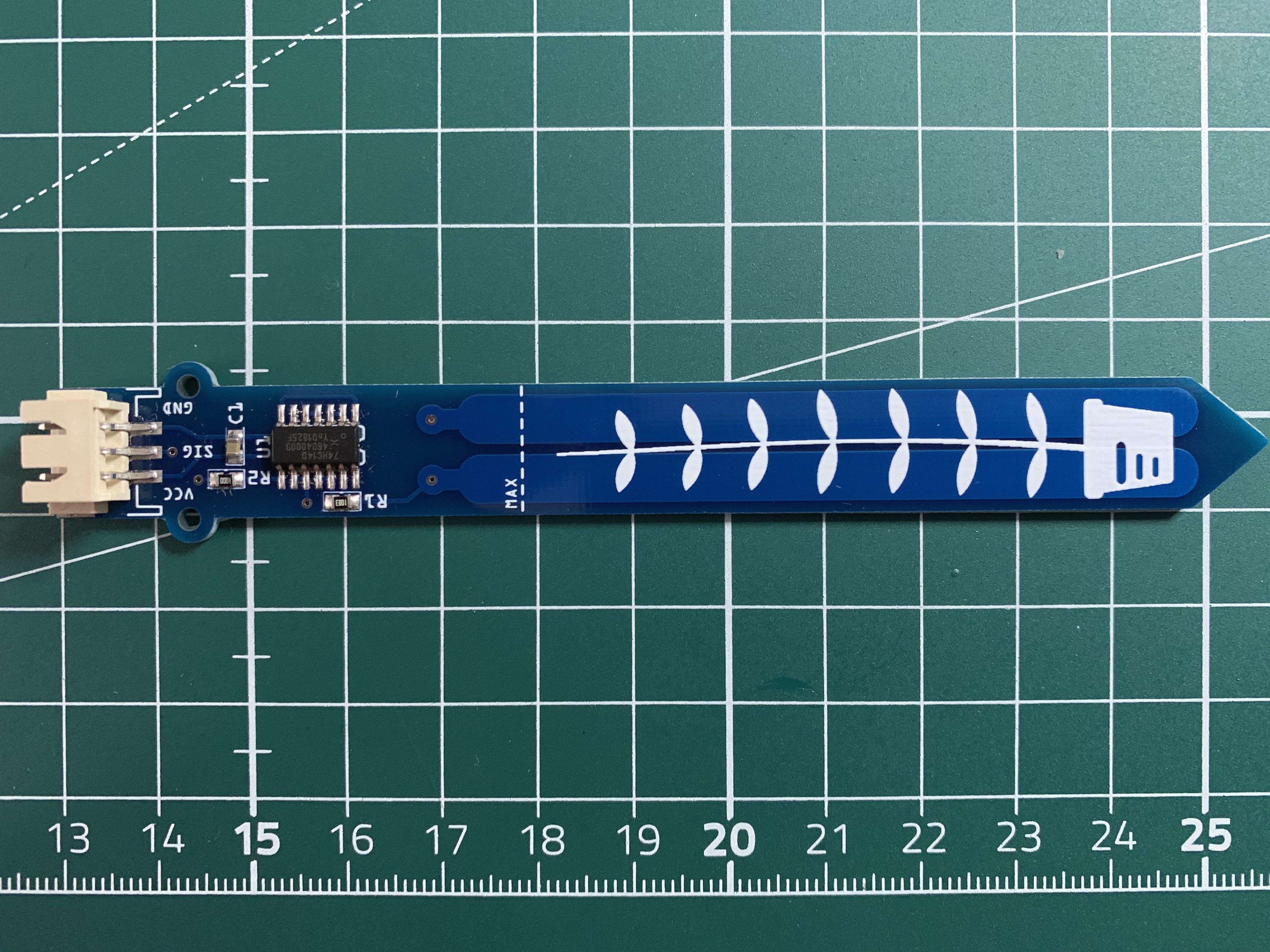
Capacitive soil moisture sensor gerber rendering:
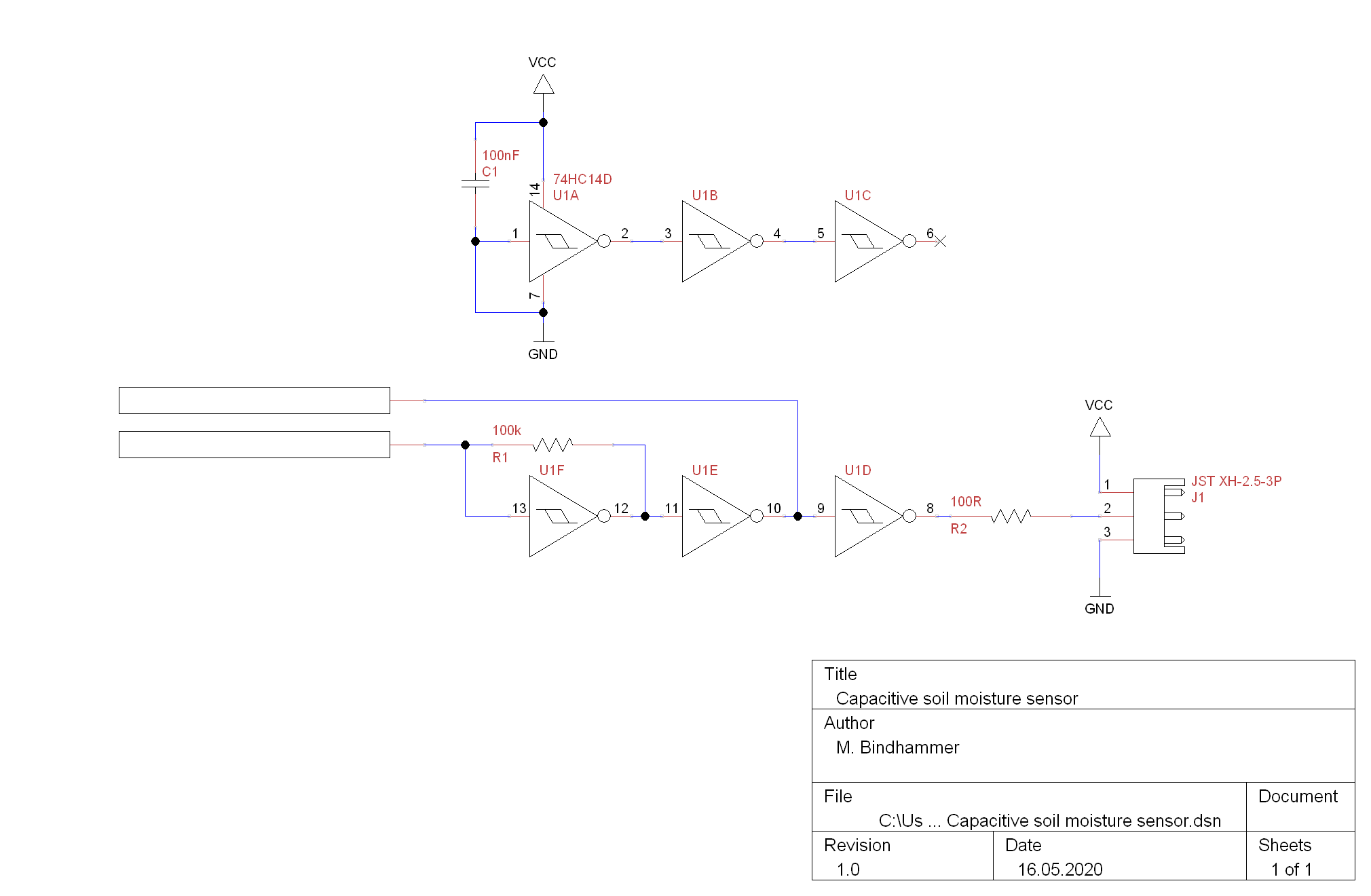
The sensor has two electrodes that form a plate capacitor. The soil surrounding the capacitor serves as dielectric and influences its capacity - the more humid the soil, the greater the capacity of the capacitor. The capacitor, a resistor that charges the capacitor and 3 inverting Schmitt triggers (one stage just acts as a buffer) form a simple oscillator whose frequency depends on the capacity of the capacitor. The frequency is approximately in the range of 40 to 400kHz and can be measured via
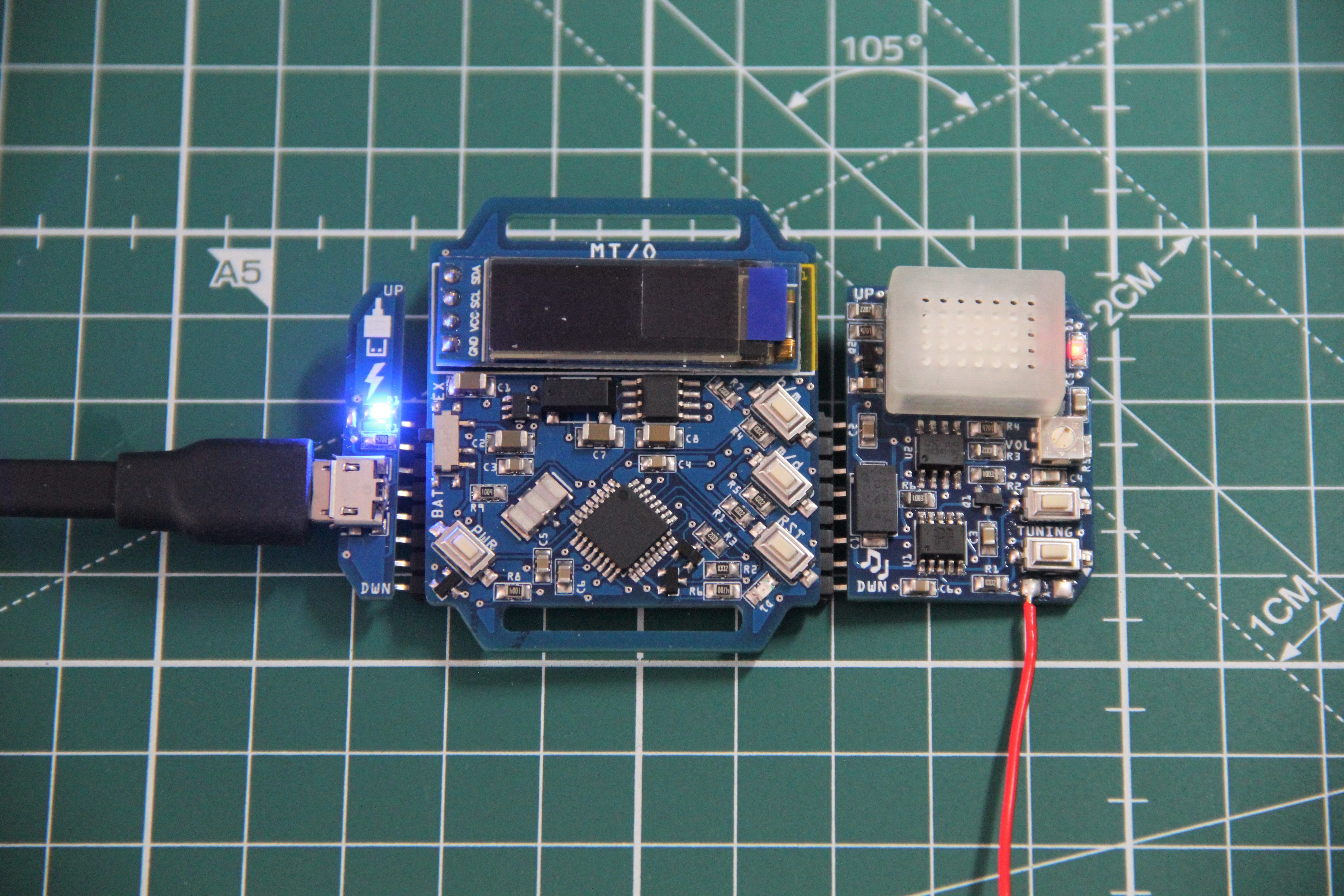
pulseIn()command and analyzed by the microcontroller.Populated PCB:Test code for the soil moisture sensor:int pulseIn_pin = 7; void setup() { pinMode(pulseIn_pin, INPUT); Serial.begin(9600); } void loop() { unsigned long duration; duration = pulseIn(pulseIn_pin, HIGH); int moisture; if (duration > 27) duration = 27; moisture = map(duration, 0, 27, 0, 100); Serial.print("Soil moisture: "); Serial.print(moisture); Serial.println('%'); delay(500); }While the soil moisture sensor is easy to manufacture, it is difficult to find a suitable micro water pump, if possible mountable on a PCB with the lowest possible power consumption, 3V operating voltage, self-priming, whether piezo, membrane, peristaltic or paddle wheel. These pumps are available in all these designs and requirements in the medical field, but they are very expensive and cannot be bought by private individuals. I have experimented in the past with piezo pumps from medical supplies for a medical related project, these pumps would be perfect, but it is disproportionate to water the indoor plant with a pump that costs $150 or more.
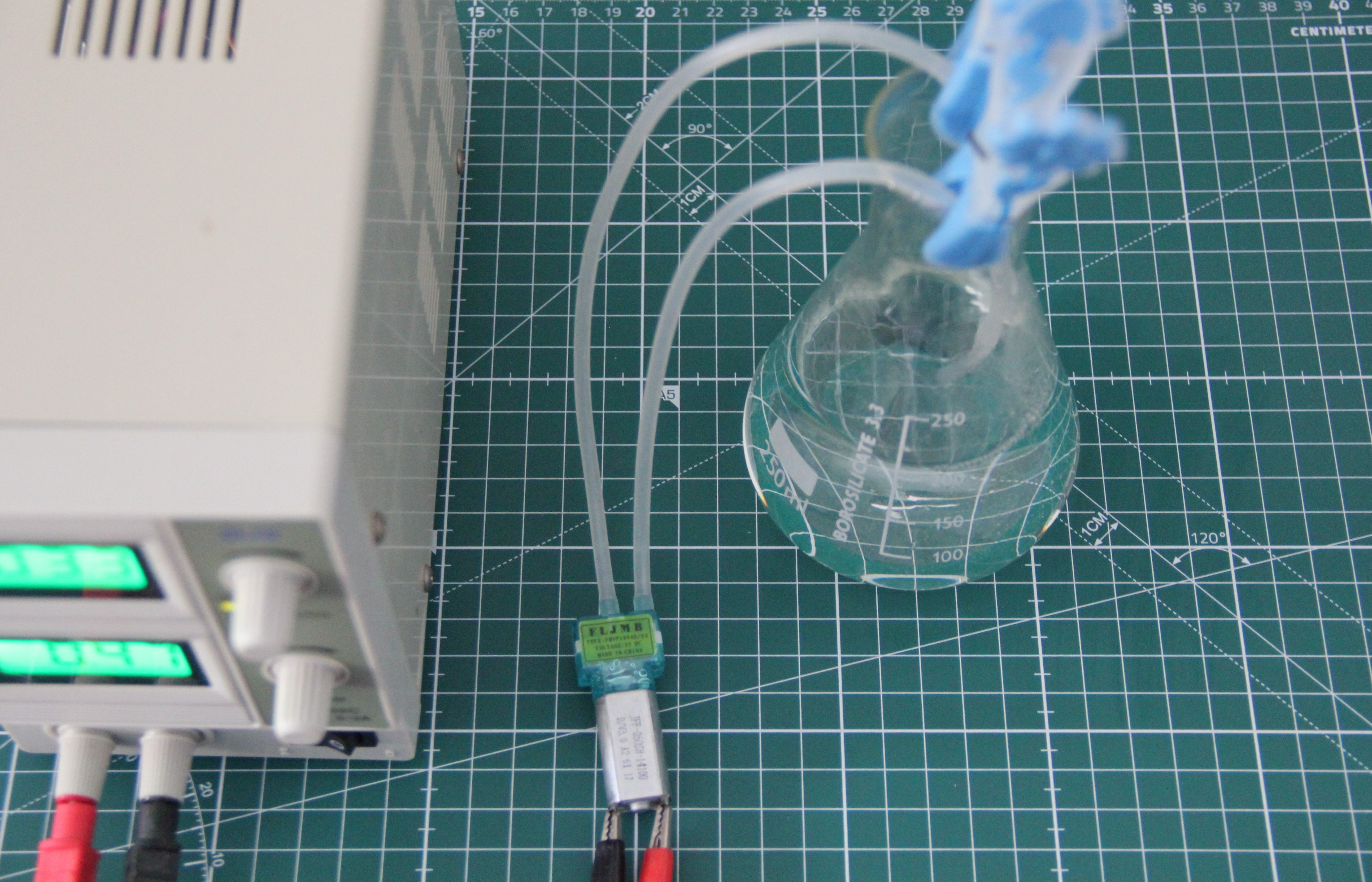
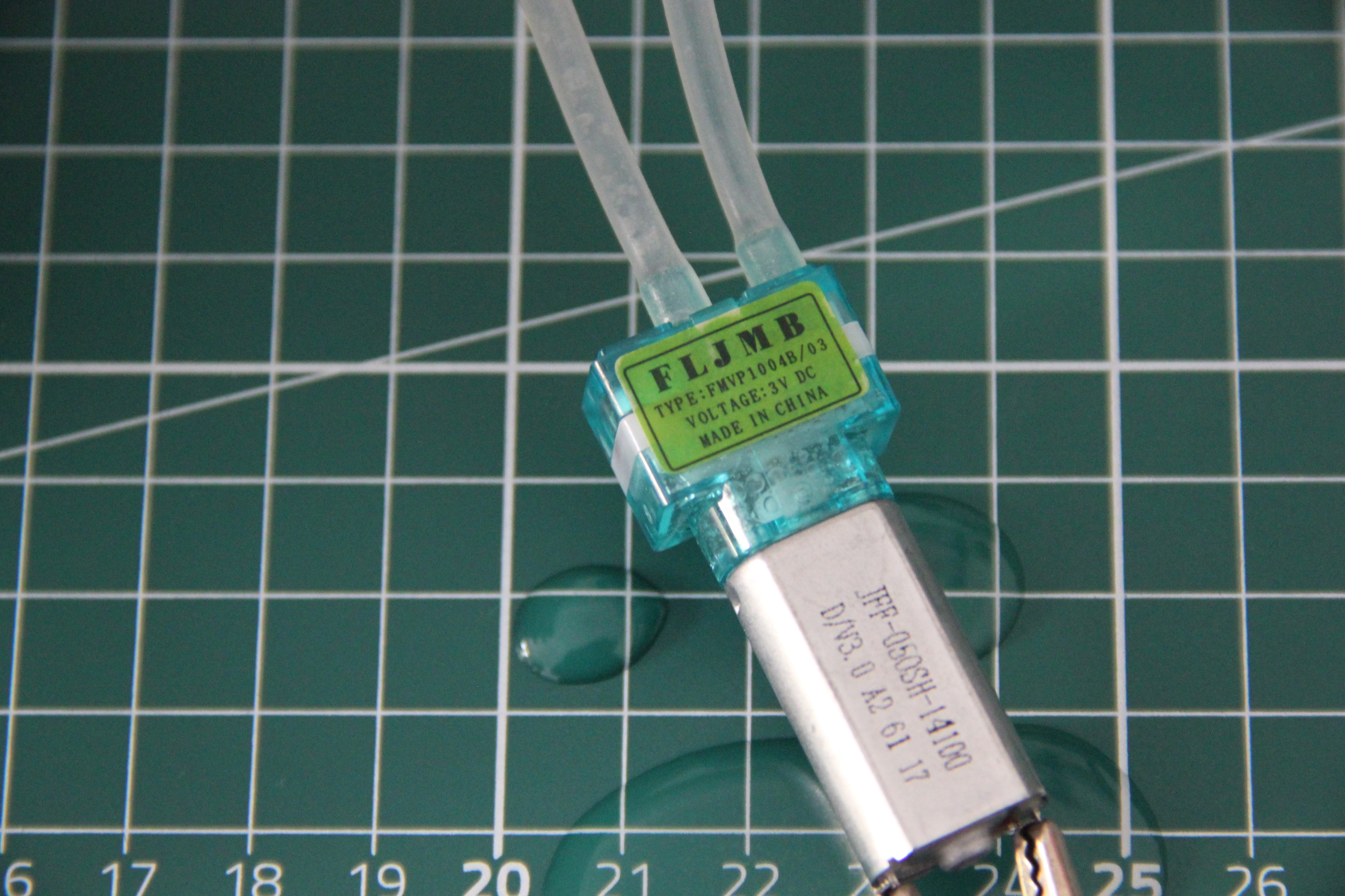
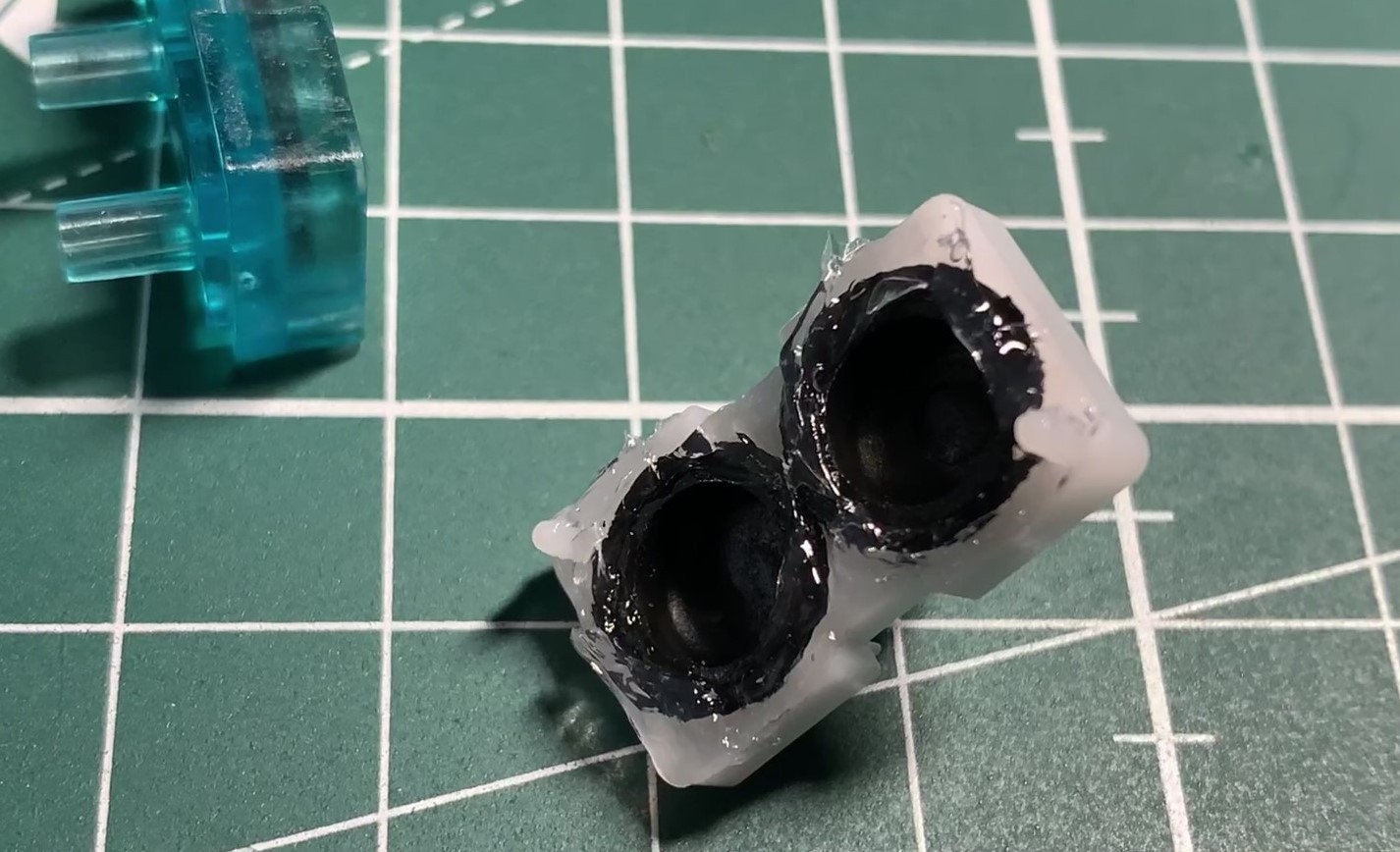
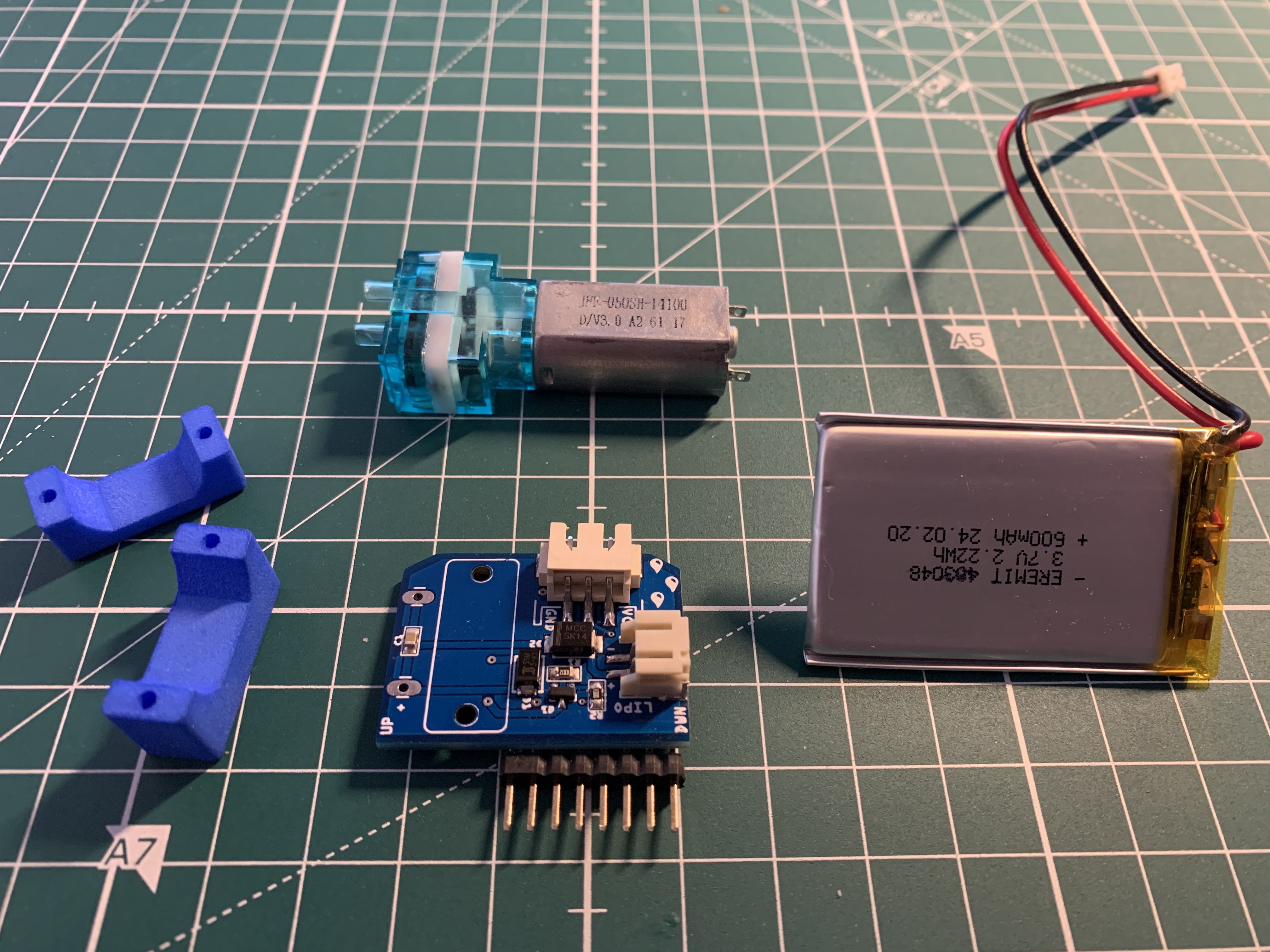
The other day I found these micro pumps on Ebay (FMVP1004B-03). They are actually intended for air (pumping up the cuff of blood pressure monitors), but the sparse data also suggested that they can be used to handle water as well. It works but unfortunately they leak after a few minutes.
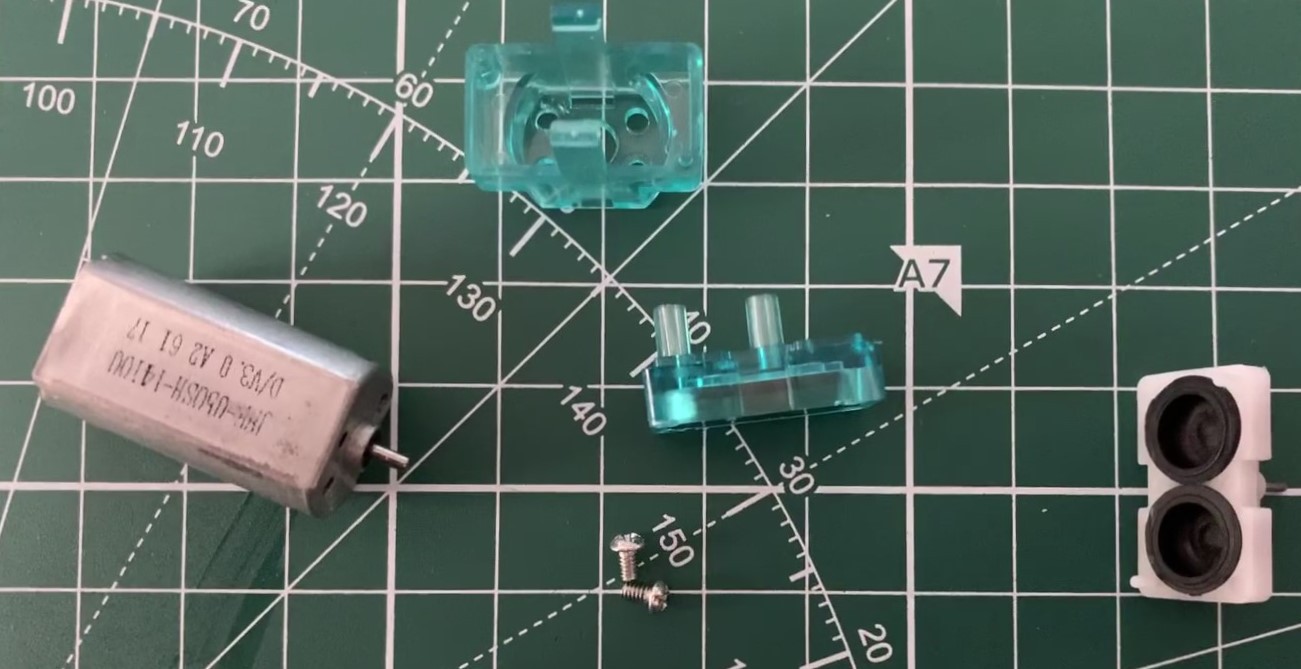
After disassembling the pump, the reason for the leakage became obvious.
The two sealing surfaces of the rubber bellows are not pressed strongly enough against the counterpart, because the pump body is not screwed together, it is only held together by two clamps. The two sealing surfaces of the rubber bellows were coated with silicone and the pump body was reassembled. Excess silicone was removed. After curing the pump can be tested again.
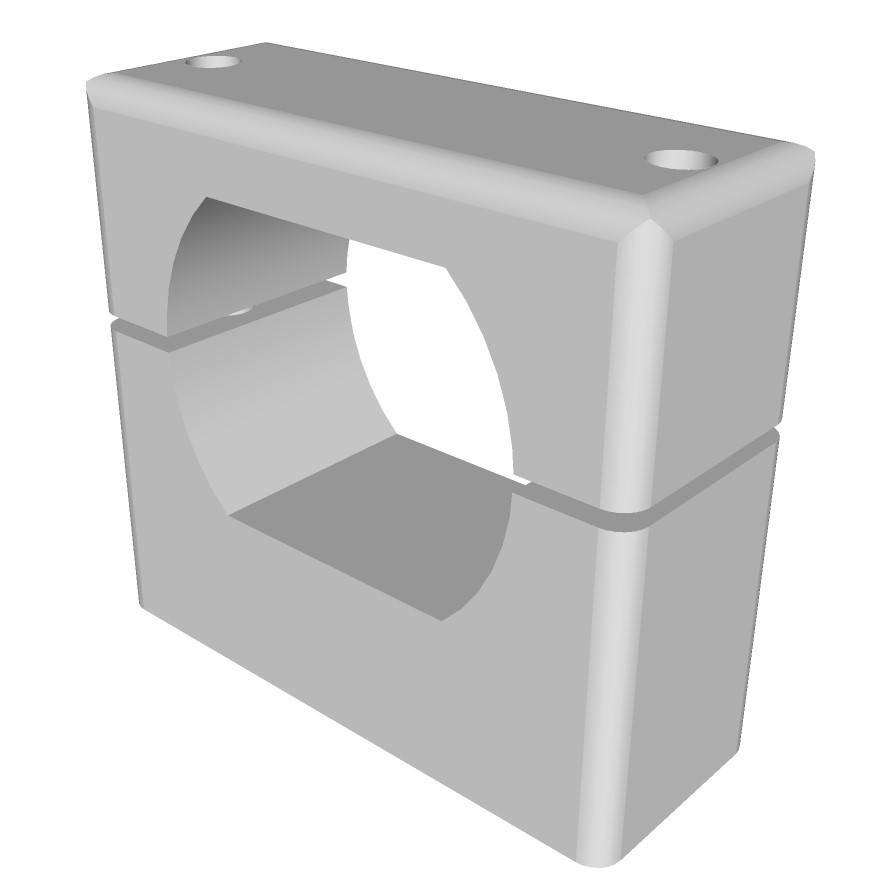
In the meantime, a 3-model of the pump's mounting on the circuit board has already been made:
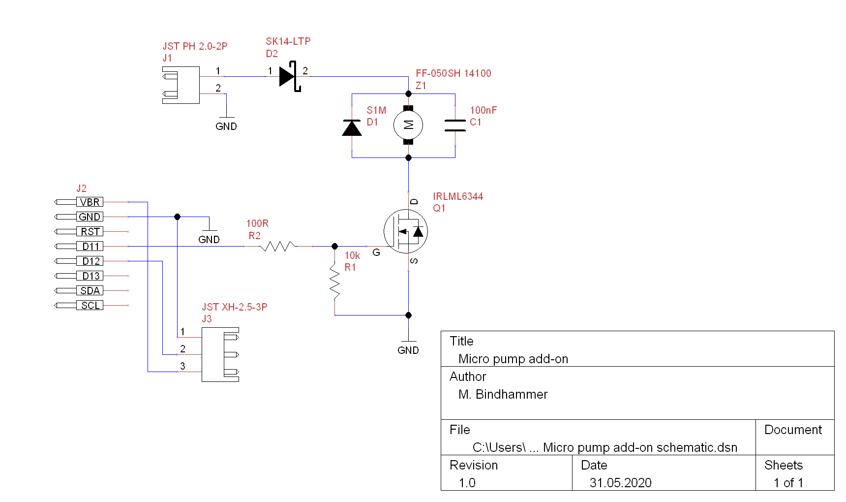
As already suspected, the silicone seals the small pump very well, it can now easily be used for water. The pump draws about 500mA during operation, which is quite a lot, even if PWM is used later. The motor is a fake Mabuchi FF-050SH 14100, a FF-050SH 07400 would be better, it has a much lower revolution speed and draws much less current. But since I didn't find a source of supply, I decided not to exchange the motor and to run it with a LIPO. Here is the schematic of the micro pump add-on, to which the soil moisture sensor is also connected:
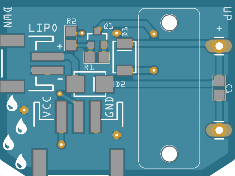
The PCB dimensions are the same as for the FM radio, 34.5 x 26mm:
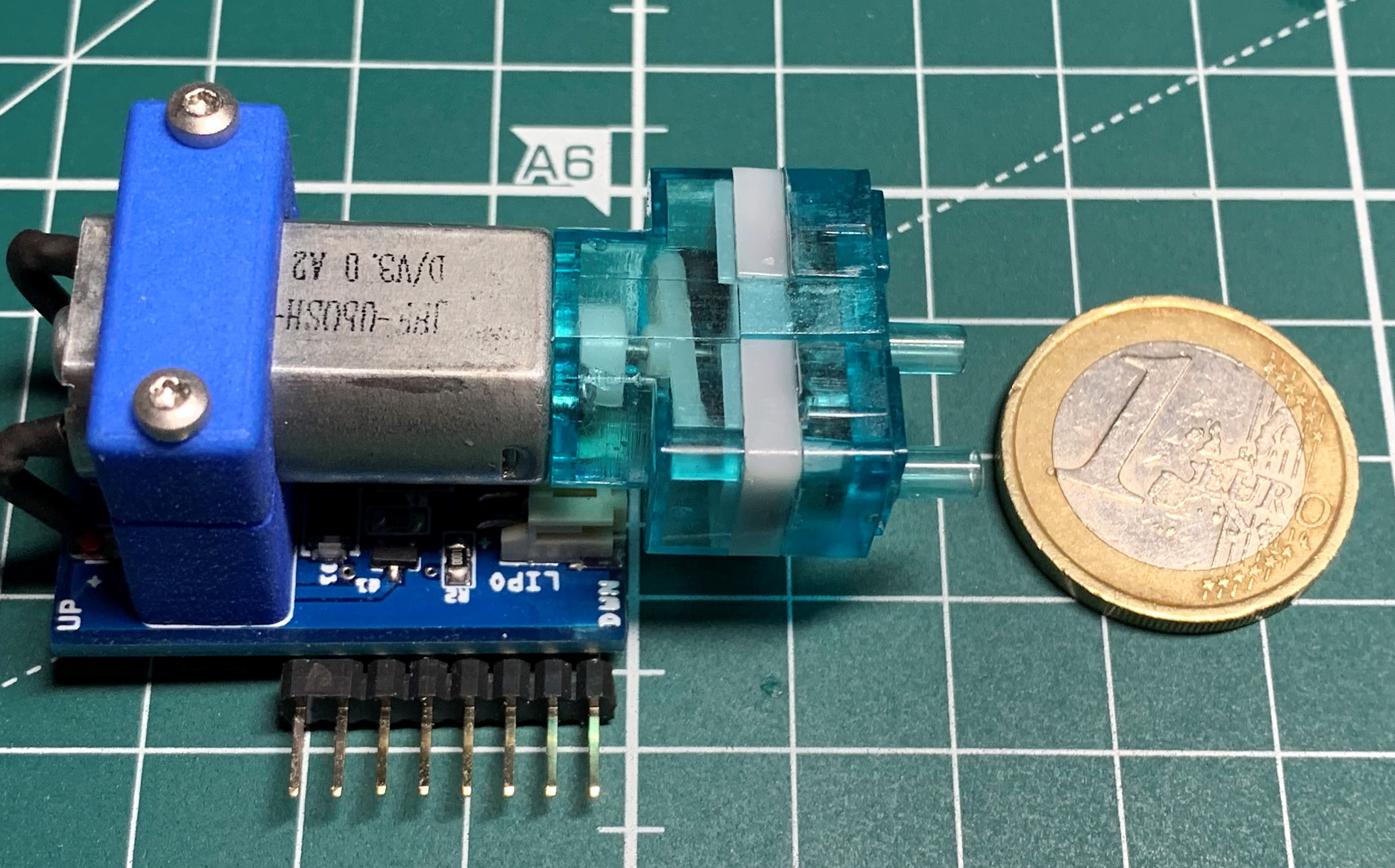
3-D printed micro pump holder, populated PCB, LIPO battery and modified micro pump:
Finished micro water pump add-on:
-
Programming the first prototype
04/28/2020 at 15:49 • 0 commentsAfter I reflowed the first board yesterday night, I started programming today. First I burned the bootloader onto the board to dublicate the settings of the Arduino Pro Mini (8MHz, 3.3V), wrote a test code (kinda annoying via ISP to develope code) and set the RTC to the date & time on my laptop. Then I uploaded the code again via ISP.
Test code:
#include "RTClib.h" #include <Arduino.h> #include <U8g2lib.h> #include <Wire.h> U8G2_SSD1306_128X32_UNIVISION_F_HW_I2C u8g2(U8G2_R0); RTC_PCF8523 rtc; char daysOfTheWeek[7][12] = {"Sun", "Mon", "Tue", "Wed", "Thu", "Fri", "Sat"}; int running_index = 0; void setup () { // Serial.begin(57600); pinMode(5, OUTPUT); digitalWrite(5, LOW); // Keep device switched on after PWR button was pressed u8g2.begin(); rtc.begin(); if (! rtc.initialized()) { // Serial.println("RTC is NOT running!"); // following line sets the RTC to the date & time this sketch was compiled // rtc.adjust(DateTime(F(__DATE__), F(__TIME__))); // This line sets the RTC with an explicit date & time, for example to set // January 21, 2014 at 3am you would call: // rtc.adjust(DateTime(2014, 1, 21, 3, 0, 0)); } } void loop () { DateTime now = rtc.now(); if(running_index < 2) { u8g2.clearBuffer(); u8g2.setFont(u8g2_font_logisoso28_tr); u8g2.setCursor(0, 32); // Seperate cursor position from print statement u8g2.print(now.hour()); u8g2.print(":"); if(now.minute() < 10) u8g2.print("0"); u8g2.print(now.minute()); u8g2.print(":"); if(now.second() < 10) u8g2.print("0"); u8g2.print(now.second()); u8g2.sendBuffer(); } if(running_index > 1 && running_index < 3) { u8g2.clearBuffer(); u8g2.setFont(u8g2_font_logisoso22_tr); u8g2.setCursor(0, 32); u8g2.print(daysOfTheWeek[now.dayOfTheWeek()]); u8g2.print(" "); u8g2.print(now.day()); u8g2.print("."); if(now.month() < 10) u8g2.print("0"); u8g2.print(now.month()); u8g2.print("."); u8g2.sendBuffer(); } delay(1000); running_index ++; if(running_index > 3) { u8g2.setPowerSave(1); pinMode(5, INPUT); // Switch device off } } -
Boot time and BOD
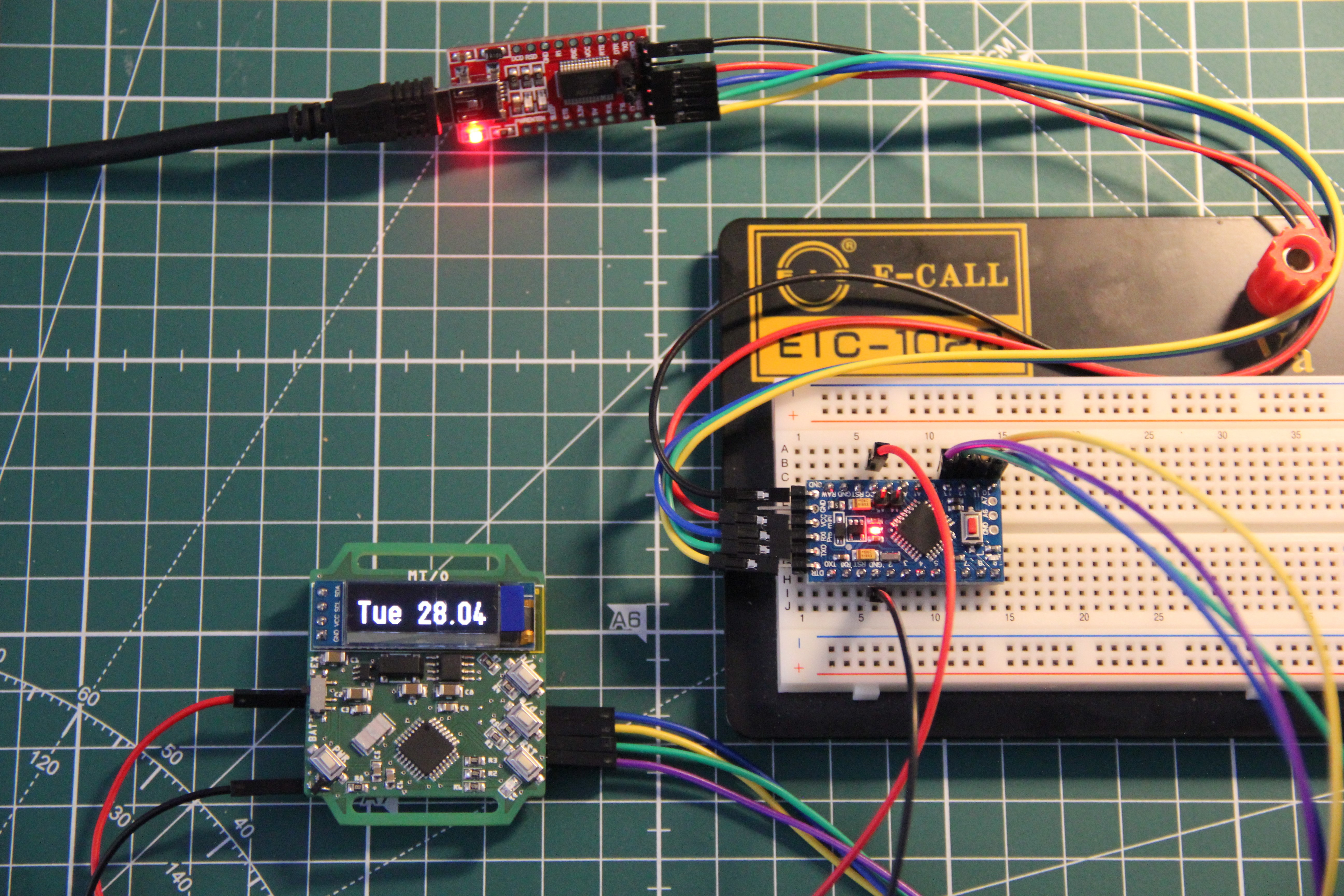
04/24/2020 at 15:01 • 0 commentsThe ATmega328P running on 8MHz needs a few seconds to boot after power is applied when using a bootloader. This is bad. The watch should show the time immediately after power-on. What to do? Using no bootloader at all on the watch's microcontroller! Programming the watch via ISP. Downside: need an Arduino Pro Mini or similar as a programmer and code upload is slow.
Here is my experiment setup. Without bootloader time/date is nearly shown without delay after power-up:
Seems also, according to the datasheet, the operating voltage for the ATmega328P is now only 2.7 to 5.5V, not starting at 1.8V anymore. The extended fuse can only be set to disable the BOD (0xFF), 2.7V (0xFD) or 4.3V (0xFC).
Note, the extended fuse only uses the lower 3 bits. Unused fuse bits read back as 1.
0xFE (110), before the setting for 1.8V, is now reserved. Let's see, if I disable the BOD. The 128 x 32 OLED (I removed the voltage regulator on its breakout board) would still run at 2V. On the other hand, a watch should be a reliable device. Using BOD, the watch will execute brown-out resets when the battery voltage dips below the brownout threshold, typically 2.7V (min. 2.5V, max. 2.9V). This restarts the code, which restarts the display, causing another brown-out…repeating until the battery is dead. Without BOD the ATmega328P will start to behave erratically at some point, and may spontaneously jump to any random memory location. Also not good. Could be that the code become corrupted, means, we would need to re-flash the watch. Not good at all.
I need to do some more testing. Finally, I also could use rechargeable LIR-2032 instead of CR2032. They have a rated voltage of 3.6V, lower capacity though (approx. 45mAh).
MI/O
Tiny microcontroller dev board, wristwatch and timer "It's not a smart watch, it's a watch for smart people"