Close
0%
0%

Fanatec ClubSport Shifter SQ v1.5 USB adapter DIY

Connect the shifter thru USB (HID gamepad) to PC, using an Arduino Due.

Similar projects worth following
Story: I ordered a Fanatec ClubSport Shifter SQ v1.5 [1] for my new sim-racing setup, alongside with its "official" USB adapter. Unfortunately the package containing the USB adapter was lost in transit and re-shipping takes forever, so I decided to quickly hack one together myself.Obviously, the PC side requires a USB HID gamepad interface, which limits the MCU choices. Looking around, I found an Arduino Due catching dust. Sure it's an overkill but I couldn't care less.The Shifter has a single RJ12 (6P6C) jack on its back --- power goes in, analog signals go out. After some wiring and simple Arduino code, it is now working happily in my racing games.[1]: https://fanatec.com/us-en/shifters-others/clubsport-shifter-sq-v-1.5

Full Arduino sketch (works on Due): https://gist.github.com/summivox/cfbcb8d309d416cefc3c0df10379339f

Interface with Shifter

This unit is kinda special as it can act as either an H-pattern or a sequential shifter:

  • The H-pattern mode should be presented as 1 button for each gear: 7 forward and 1 reverse. Neutral is represented by all buttons released.
  • The sequential mode should be presented as 2 buttons: shift up and shift down.
  • A push/pull lever near the bottom of the base selects the mode.

After some googling I found a legit looking pinout / schematic in a forum post:

  1. GND
  2. low = H-pattern, high = sequential
  3. internally shorted to pin 2
  4. X axis (H-pattern); lever push (sequential)
  5. Y axis (H-pattern); lever pull (sequential)
  6. VCC

Pin numbers are for RJ12 (6P6C).

Just to be safe though, I opened the shifter up to make sure that VCC and GND matches the pinout listed above. The trick is to locate the power and ground pins on ICs:
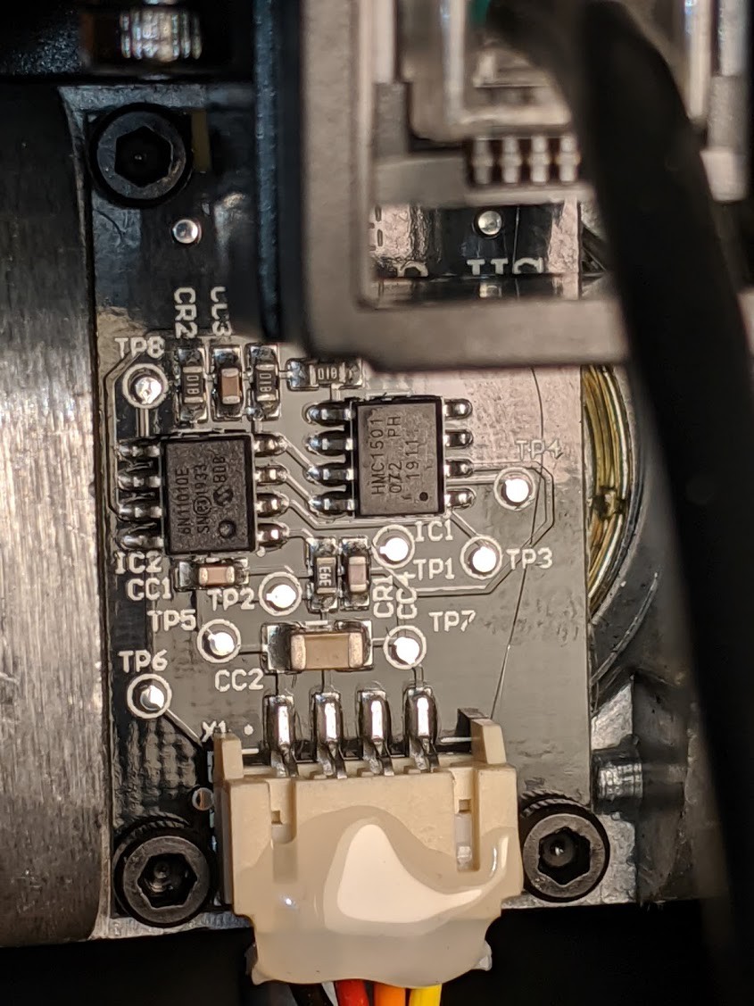
The chip on the left is an MCP6N11-010, an amplifier. Knowing its pin 4 is GND and pin 7 is VCC, some continuity checks is enough to confirm the pinout.

While I don't have any RJ12 jacks/plugs around, the shifter does come with two cables --- one RJ12-to-RJ12 for connecting the shifter to "modern" Fanatec wheels, and one RJ12-to-PS/2 for "legacy" wheels. I don't have any so I decided to turn the legacy cable into a pigtail. Well, not quite a pigtail --- I happen to have an IDC header around so I just shoved the individual wires into the header and clamped it down.

Now with a cable, I fired up my bench power supply and scope to inspect the outputs:

  • In the H-pattern mode, X axis continuously tracks the left-right angle of the stick, while the Y axis has 3 discrete states: forward, center, and backward.
  • In the sequential mode, both "X axis" and "Y axis" outputs are active-low discrete signals (simple button). Pushing the stick makes "X" go low; pulling makes "Y" go low.

Sounds pretty simple. I slapped on some naive debouncing logic and logged everything through serial. Looks to be working.

USB HID gamepad on Arduino Due

I simply pulled in the Arduino Joystick Library. It works out of the box.

BTW: This is why I am reluctant to use STM32, my all-time favorite MCU series, for anything USB. Instead of over-complicated proprietary "middle-ware" on under-documented hardware, I'd rather have a simple open-source library that gets the shit done.

Limitations

I did not include any calibration capability for the H-pattern mode. Everything is hard-coded. While this is okay for the Y axis since it only has 3 states (high, mid, low), the X axis is more crowded and MIGHT be different from unit to unit. If the hard-coded constants are not good enough for you, simply upload an analog input logger sketch and figure out the correct values yourself.

  • 1 × Arduino Due

  • Shifter Boards - Reverse Engineered!

    Yin Zhong04/26/2020 at 06:49 0 comments

    Even though it's enough to treat the shifter as a black box if the end goal is just to interface with it, curiosity took over and I decided to trace out both boards on the shifter.

    X-Axis Sensor Board

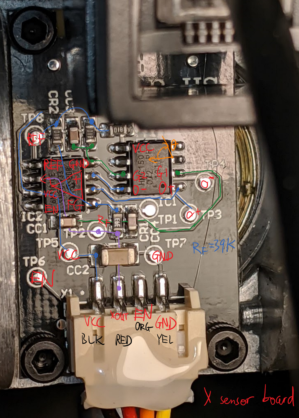
    This is actually very simple: HMC1501 (SOIC-8 package on the right), a magnetic encoder chip, outputs a differential voltage proportional to sin(2*theta) of a magnet rotating underneath it. This differential voltage is amplified by an instrumentation amplifier, MCP6N11-010, to its left. Reference voltage for the output is 1/2 VCC, generated with a resistor divider. The amplifier comes with an ENABLE pin --- driving it low turns the output high-Z.

    Y-Axis / Main Board

    This shouldn't be hard, but it tripped me up for good mainly due to its, uh, gross inefficiency.

    Recall the behavior of the shifter:

    • When the shifter is in H-pattern mode:
      • SEQ pin is LOW
      • X pin outputs X axis angle (the output from X axis board)
      • Y pin is:
        • VCC if lever is in R/1/3/5/7 (forward)
        • 1/2 VCC if lever is in the center / neutral
        • 0 if lever is in 2/4/6 (backward)
    • When the shifter is in Sequential mode:
      • SEQ pin is HIGH
      • X pin goes LOW if the lever is pushed forward (gear 3)
      • Y pin goes LOW if the lever is pulled backward (gear 4)

    Let's start from each part...

    Hall Effect Switches

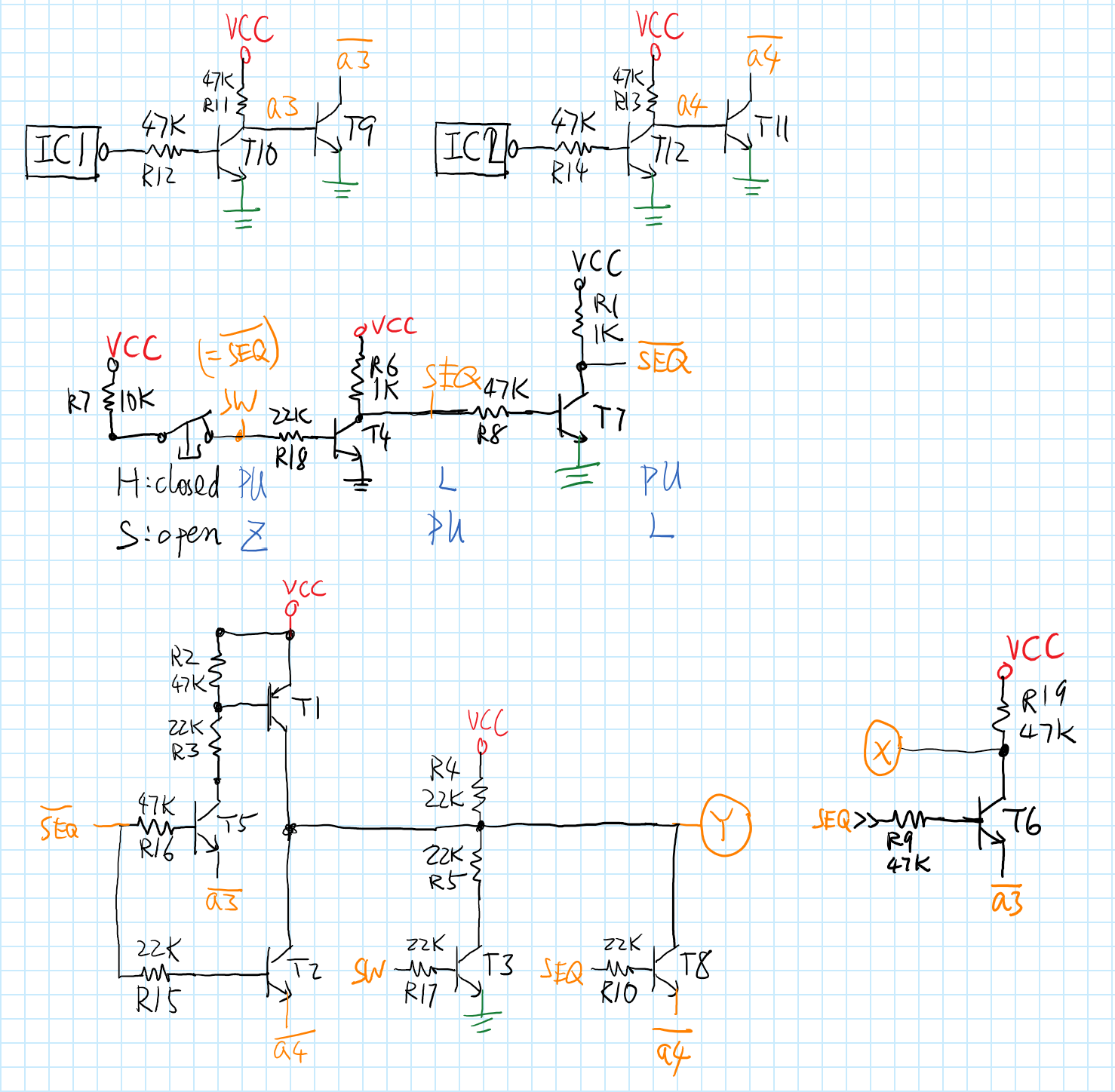
    The Y position is sensed by IC1 and IC2, both of which are SL353 hall-effect switches. These happen to have push-pull active-low output, so if a magnet is around the output is driven LOW; otherwise the output is driven HIGH. When the shifter lever is pushed forward, the magnet (right center) goes under IC1; backward, IC2.

    The push-pull active-low output from each switch is put through 2 inverters (T9~12) and becomes an active-low open drain output. No other signals from this chain is used. I wonder why don't they just use a hall switch that outputs open drain in the first place; easy 4 transistors and tons of board space saved.

    Mode Switch / Enable

    A limit switch is connected to the 2P connector in the bottom left. It is closed in H mode, open in SEQ mode. This also went through 2 inverters. The designer sure loves his/her double inverters...

    Anyway, SEQ pin is tapped off the first inverter here, while the ENABLE pin for X-axis is tapped off the second (X axis sensor enabled only in H mode).

    Y axis behavior

    In H mode, T3 is on, T8 is off, so R4/R5 pulls the Y pin to roughly 1/2 VCC. T5 and T2 are both on, so T1 and T2 forms a push-pull output stage, triggered by open-drain outputs from the hall switches.

    In SEQ mode, T3 is off, so only R4 pulls the Y pin to VCC. T8 is on, so only IC2 open-drain output can pull the Y pin to LOW.

    Surely enough, neither T2 nor T8 are necessary. Regardless of SEQ signal, IC2 open-drain output is effectively connected to the Y pin anyway.

    X axis behavior

    In SEQ mode, the X-axis board is disabled, and instead IC1 open-drain output can pull the X-pin.

    Conclusion

    Only T1,2,3,5,6 are really necessary. That's 5 out of the original 12. Both the design and layout looked grossly incompetent. Improvements would not only simplify the circuit, but also make it a lot more robust.

    Why did I even waste time on this... I must have been really bored...

View project log

Enjoy this project?

Share

Discussions

Alec Barron wrote 05/07/2023 at 05:25 point

i followed your project using a generic leonardo r3 and im not able to get any input read. i changed the first line from cstdint to stdint.h, and commented out analogreadresolution as they were both causing errors for me. i then followed your pinout putting P2 to A2, P4 to A0, P5 to A1, P1 to GND P6 to 3.3V. i uploaded the sketch fine, and my pc detects the leonardo as a usb game pad and sees the shifter inputs as buttons, but input from the shifter is not doing anything. if you could provide any guidance on if i made an error with the pins, or if i need to use readresolution somehow, it would be much appreciated!

  Are you sure? yes | no

hylonochoa wrote 03/12/2022 at 22:26 point

can a connection be made using a pro micro?

  Are you sure? yes | no

Similar Projects

Does this project spark your interest?

Become a member to follow this project and never miss any updates