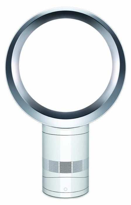
An air multiplier, sometimes called bladeless fan, is a fan which blows air from a ring with no external blades. Its vanes are hidden in its base and direct the collected airflow through a hollow tube or toroid, blowing a thin high-velocity smooth airflow from holes or a continuous slot across the surface of the tube or toroid. The first concept was created by Toshiba in 1981.-Wikipedia
Step 1: AC to DC Circuit
Input AC 220V; need to output 15V DC power supply, this is the very classic MP150 non-isolated power supply circuit. By adjusting the current of the control terminal to change the amplitude, to achieve precise adjustment purposes.
Step 2: Power Detection and Buck Circuit
The input voltage can be directly detected by MCU after voltage division and can be used for circuit protection.
15V dc voltage through 78L05 buck voltage to 5V, for MCU use
Step 3: MCU
Here we use SN32F7051BF. You can get it on LCSC
MCU is responsible for gear setting and switching, indicating the running status, the most important role in motor control.
Step 4: Brushless DC Motor
The above is a three-phase full-bridge drive circuit for a brushless motor. It uses six N-channel MOSFETs (FMD3N50E5) as power output components, and the output current can reach tens of amperes during operation.
Use IR2101 as the drive of MOS tube, IR2101 is a dual-channel, gate drive, high-voltage high-speed power driver. SCM drives IR2101 by outputting controllable PWM signal
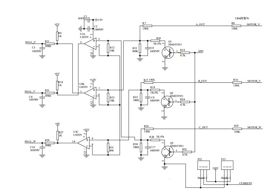
Step 5: Brushless Motor Zero Crossing Problem
The brushless motor senses the position of the permanent magnet's magnetic pole through the hall element and transmits it to MCU. The MCU timely switches the current direction in the coil to ensure the magnetic force in the right direction to drive the motor
Step 6: Brushless Motor Zero Crossing Problem
The brushless motor senses the position of the permanent magnet's magnetic pole through the hall element and transmits it to MCU. The MCU timely switches the current direction in the coil to ensure the magnetic force in the right direction to drive the motor
Step 7: Indicating Operating Status
Common anode,by changing the cathode level, the LED is turned on and off, indicating various working states
If you have better suggestions for this solution, Welcome to modify these schematics on EasyEDA
Design by EasyEDA
PCB sample provided by JLCPCB
Components provided by LCSC




 Mrinnovative
 sciencetoolbar