deʃhipu
-
Assembled and Flashed
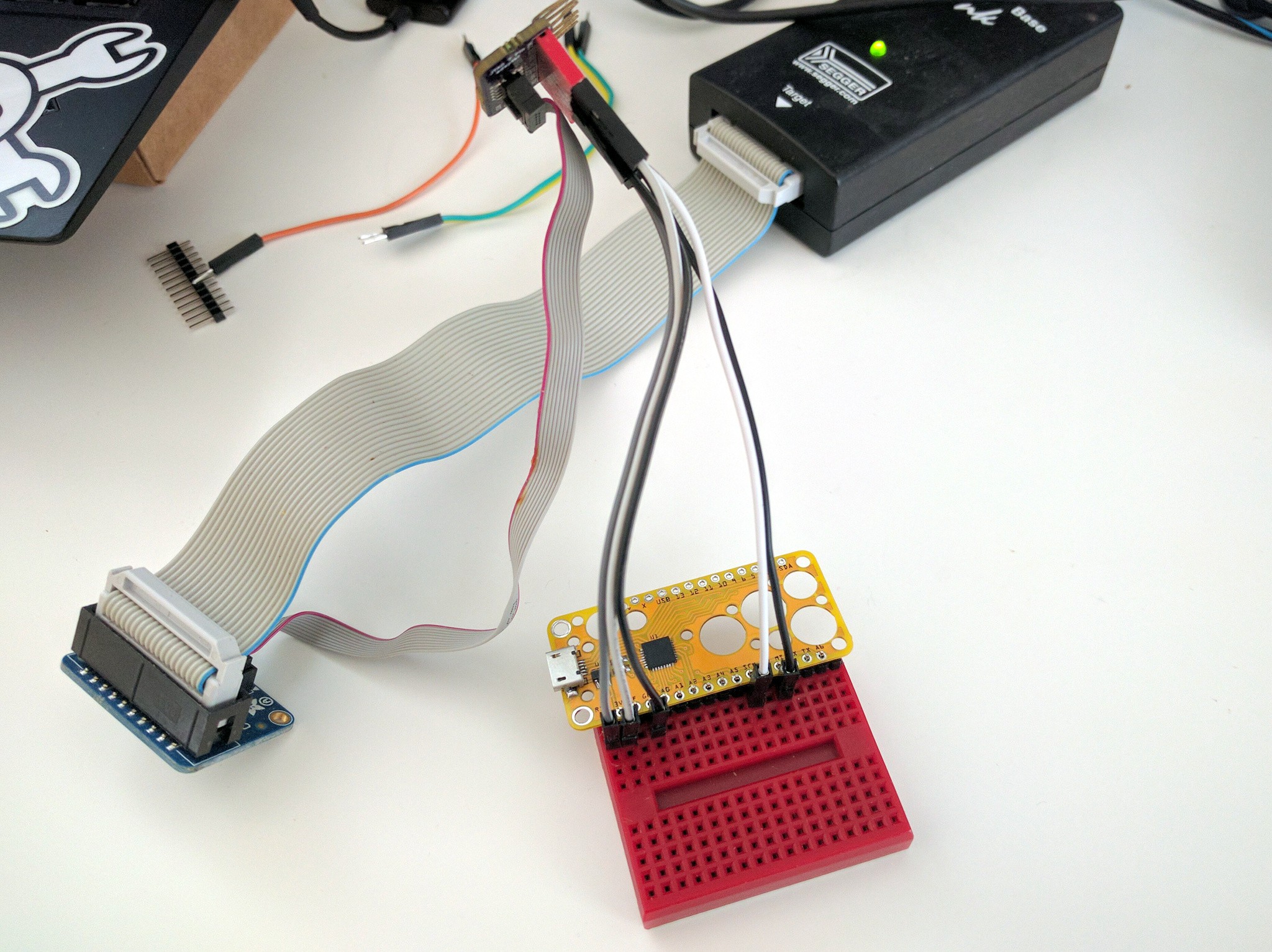
05/22/2020 at 13:28 • 0 commentsSince today is a holiday for me, I had the time to immediately assemble of Fluff M0 and flash it with the bootloader and CircuitPython. Since all pins, including the SWD and SWC are broken out, flashing is simple:
![]()
You just have to connect 3V to VCC, GND to GND, SCK to SWC and MISO to SWD. Then a couple of terminal commands:
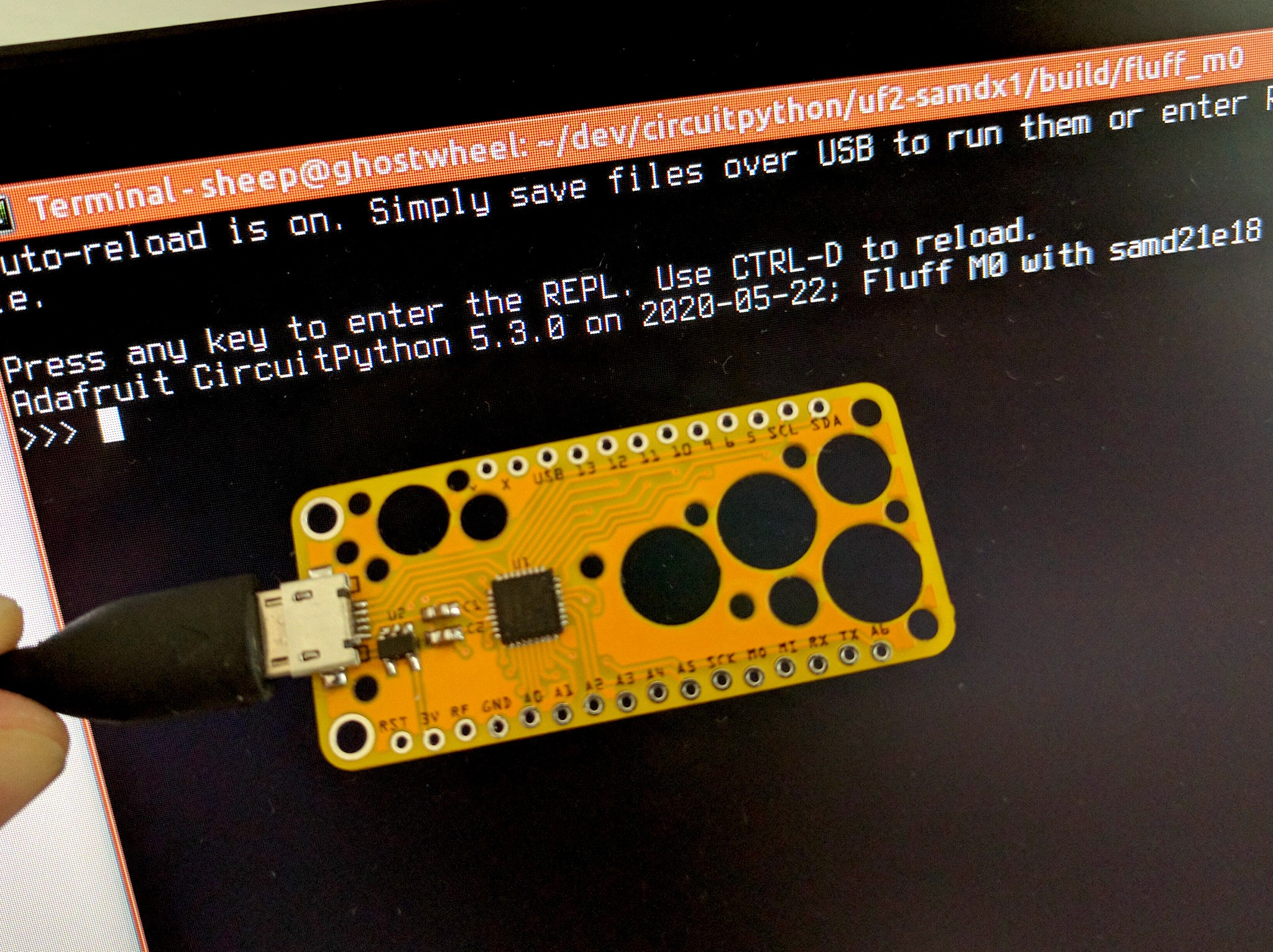
$ JLinkExe -if SWD -device ATSAMD21E18 -speed 4000kHz
SEGGER J-Link Commander V6.40 (Compiled Oct 26 2018 15:08:38)
DLL version V6.40, compiled Oct 26 2018 15:08:28

Connecting to J-Link via USB...O.K.
Firmware: J-Link V10 compiled Oct 26 2018 12:04:17
Hardware version: V10.10
S/N: 50112638
License(s): GDB
VTref=3.290V


Type "connect" to establish a target connection, '?' for help
J-Link>connect
Device "ATSAMD21E18" selected.


Connecting to target via SWD
InitTarget()
Found SW-DP with ID 0x0BC11477
Scanning AP map to find all available APs
AP[1]: Stopped AP scan as end of AP map has been reached
AP[0]: AHB-AP (IDR: 0x04770031)
Iterating through AP map to find AHB-AP to use
AP[0]: Core found
AP[0]: AHB-AP ROM base: 0x41003000
CPUID register: 0x410CC601. Implementer code: 0x41 (ARM)
Found Cortex-M0 r0p1, Little endian.
FPUnit: 4 code (BP) slots and 0 literal slots
CoreSight components:
ROMTbl[0] @ 41003000
ROMTbl[0][0]: E00FF000, CID: B105100D, PID: 000BB4C0 ROM Table
ROMTbl[1] @ E00FF000
ROMTbl[1][0]: E000E000, CID: B105E00D, PID: 000BB008 SCS
ROMTbl[1][1]: E0001000, CID: B105E00D, PID: 000BB00A DWT
ROMTbl[1][2]: E0002000, CID: B105E00D, PID: 000BB00B FPB
ROMTbl[0][1]: 41006000, CID: B105900D, PID: 001BB932 MTB-M0+
Cortex-M0 identified.
J-Link>loadfile bootloader-fluff_m0-v3.10.0.bin 0
Downloading file [bootloader-fluff_m0-v3.10.0.bin]...
Comparing flash   [100%] Done.
Erasing flash     [100%] Done.
Programming flash [100%] Done.
Verifying flash   [100%] Done.
J-Link: Flash download: Bank 0 @ 0x00000000: 1 range affected (8192 bytes)
J-Link: Flash download: Total time needed: 0.182s (Prepare: 0.026s, Compare: 0.018s, Erase: 0.000s, Program: 0.125s, Verify: 0.008s, Restore: 0.002s)
O.K.
And the bootloader is flashed. Now the FLUFFBOOT disk appears, and we can drag the CircuitPython UF2 file to it. Done.
![]()
-
Swiss Cheese Arrived
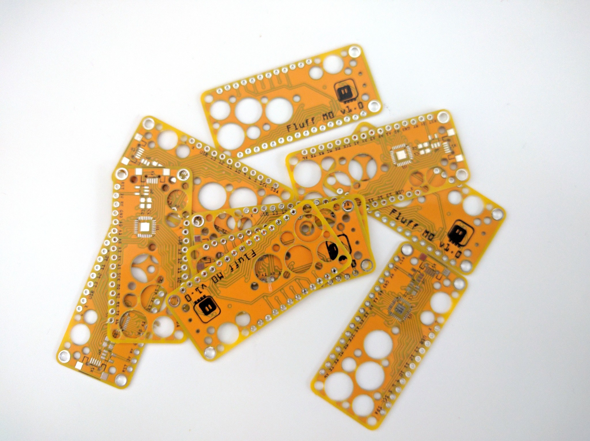
05/22/2020 at 12:26 • 0 commentsThe PCBs are here:
![]()
I also have the bootloader and the CircuitPython firmware compiled, just waiting for a separate USB VID/PID for them.
-
Beginning
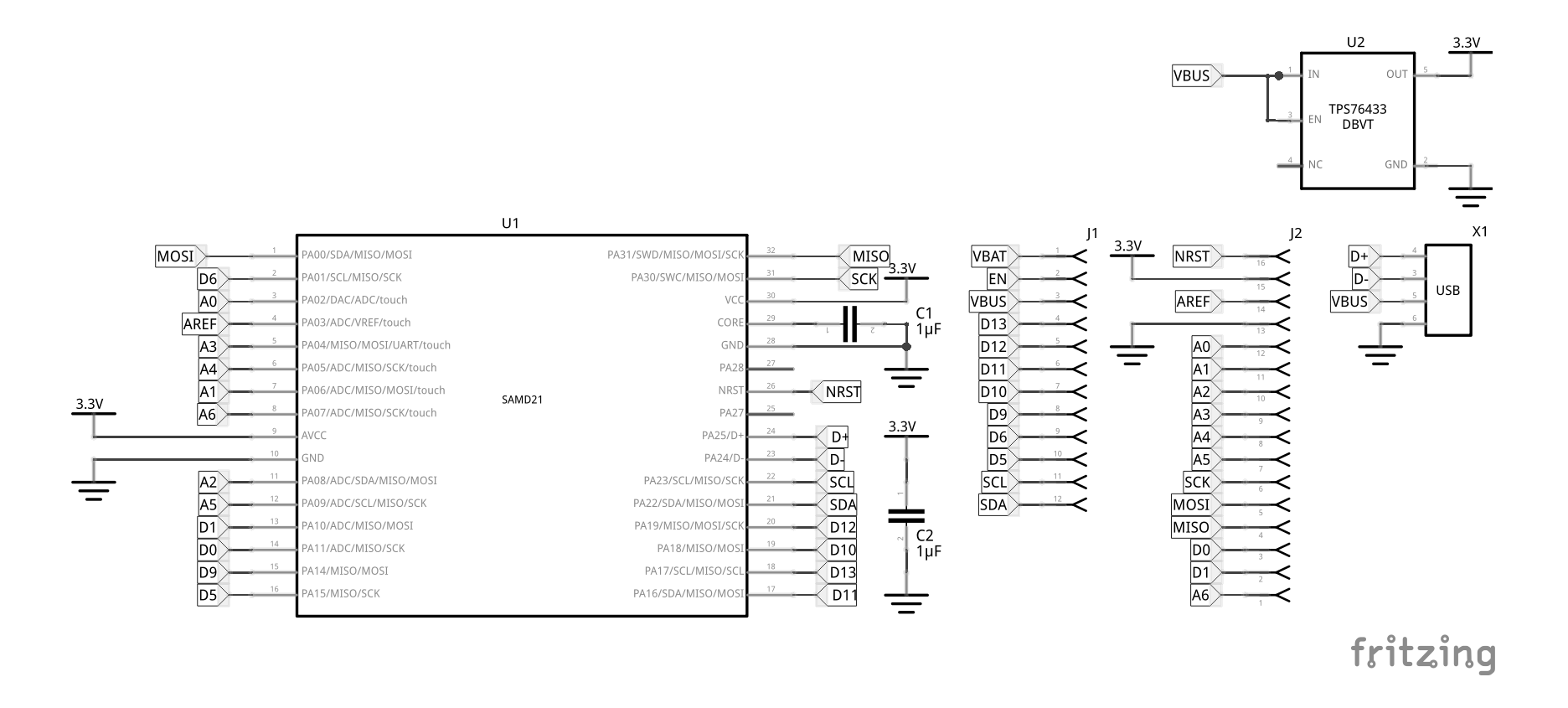
05/03/2020 at 18:04 • 0 commentsI was working on a version #Kubik M0 that would be compatible with FeatherWings, and I started to wonder whether I could do it with the QFN-32 version of the SAMD21 chip. I knew that the original Feather M0 switched to a bigger package, because there weren't enough pins, but I wanted to cheat anyways — I didn't want an external flash, and I would use the internal oscillator, which saves me a bunch of pins already. I would also use the SWD and SWC pins as regular pins — who needs debugging. So I looked at the original schematics, and started to create my own version.
I wanted to re-use the same pins as much as possible, and I mostly succeeded. Of course some of the pins are simply not there on the QFN-32 package, so I had to find substitutes for those. That includes most of the analog pins, the SPI pins, and a few of the digital pins — not very bad. In the end, I even added an extra A6 pin to the board, and had two pins unused (I choose PA27 and PA28, since they can pretty much only do GPIO and nothing else).
![]()
Then I started working on the actual PCB layout. It turns out that it's not very easy, because the pins are distributed pretty much randomly — they probably made sense on the bigger package, but with the smaller one I had to use a lot of vias. My first attempt was pretty bad, I had more vias than pins. So I deleted it and started from scratch, planning a little better this time. I came up with this:
![]()
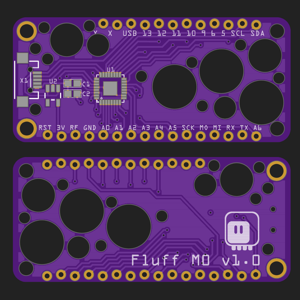
The big black circles are holes — I figured out that since the PCB is empty anyways, I can at least make it a little bit lighter. I could have used that space for a prototyping area, but it's kinda bad shape for that.
I'm going to order this with my next batch of PCBs and then make a custom CircuitPython firmware for it.