 ziggurat29
Summary
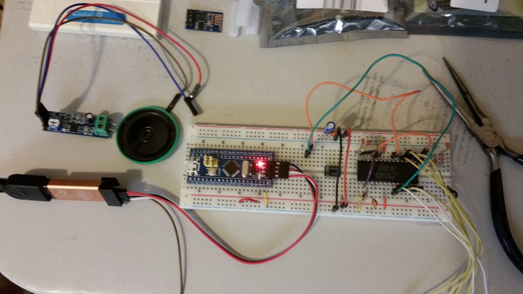
Just setting up the project and plugging stuff into the breadboard.
Deets
My motivation for this mini-project was simply to set up to get recorded phonemes. Strictly, since I already have that, and since I have already proven the concept with the python code, I really don't need to do the BluePill interface anymore, but I'm going to do it anyway for a few reasons:
- there was a cautionary statement about the quality of the existing recorded phonemes, so maybe I want to make my own recordings under a controlled environment
- I think it might be useful to someone else in some way
- more wild geese: it occurred to me that if this 'concatenate the phonemes approach works' (which it seems to), then I might be able to put the whole thing on the BluePill -- no SP0256-AL2 required! And moreover with the text-to-speech, then also no CTS256 required! Those chips have become quite rare, and are pretty expensive when you can find them. So, instead, you could just use an STM32F103 for a couple bucks (possibly also with no external crystal needed) and have it output the speech signal on a PWM line.
Anyway, it was time to gather parts and start stuffing the protoboard:
Some things:
- I am very displeased to have gotten burned on the ST-Link-V2. These are very cheap from Chinese sources, and I like to keep a pile of them on-hand for various projects that are in various stages of development, rather than just have one that I need to move around between the various projects. I had bought a batch of them some months ago and opened one of those up. It looked like an ST-Link, but the legend for the pins was quite different. I noticed the labeling was 'STC Auto Programmer' and then googled to see what the heck it was. Well, it turns out that many others have gotten burned this way before as well. So 'caveat emptor' when ordering these things from overseas. It turns out this is simply a USB-to-serial adapter using the CH340 chip. I suppose I can make use of that in some other context, but it was completely useless here. So I was back to cannibalizing another project for the ST-Link, *sigh*.
- The SP0256 specs an oddball crystal (3.12 MHz), so I am using a colorburst instead. This was commonly done, and I've heard that some folks have even overclocked it as much as 4 MHz (the sound sample on wikipedia seems to be like that).
- Since this is going to be breadboard only, I am going to reuse a separate LM386 breakout board that I already have a speaker attached to save a little time rummaging for parts.
- The SP0256 is a 5V part, and the STM32F103 is a 3.3V part. Many but not all of the STM's pins are 5V tolerant, but you have to double check. In particular, the lower port A pins are not 5V tolerant (pretty much anything that can be used as analog input is not), and I planned to use those for the address lines. I think this will work safely because those are inputs on the SP0256 side, and outputs on the STM side. But for the couple lines that come back into the STM (SBY and /ALD) those will definitely need to be on 5V tolerant pins.
- Call me a 'Nervous Nelly' if you will, but the SP0256 part is precious, so I and double and triple checking it's wiring before putting power to it. Once it's blown, that's the end of the party. The same caution applies to the STM, but I have more of those and those are cheap.
So, I am planning the pin assignments:
- port A0-7 (not tolerant) will go to the SP's address A1-A8 (hey, I didn't name these pins)
- port PB1 (not tolerant) will go to the SP's /ALD
- port PB10 (tolerant) will go to the SP's SBY
- port PB11 (tolerant) will go to the SP's /LRQ (and probably be configured as EXTI)
- and later, if/when I try to make a STM32 standalone simulator/emulator, then PB0 will be configured as PWM output
- there will be USB CDC
- I might see if I can do a UART, too. This is not required, however when debugging, USB CDC is a pain because halting the processor when single-stepping causes the USB to break, and then you have to reset and that's the end of your debugging sessions. By using a physical UART, you can use an FTDI and not break the connection (or maybe I can use that bogus programming adapter; lol!)
Next
Building the Basic BluePill Interface
Discussions
Become a Hackaday.io Member
Create an account to leave a comment. Already have an account? Log In.
I only use Platformio but I don't have a Blue pill (yet)
Are you sure? yes | no
getcha sum; they are so cheap - I don't know how they do it. I try to keep about 10 on-hand for when random projects like this come to mind so I don't have to wait for parts to come in.
I do wish 'they' would also make one with a beefier processor, e.g. an 'F415, but for a lot of things the F103 is serviceable.
Are you sure? yes | no
OK, you piqued my curiousity, and just looking, it looks like platformio would be straightforward:
https://docs.platformio.org/en/latest/frameworks/stm32cube.html
The gist seems to be that you make your project in STM32CubeMX (as I have done here), and then you run a python tool to spew out the platformio project (normally, Cube has a few known toolchains and will do this, but it doesn't do platformio itself ATPIT).
Are you sure? yes | no
Are you using Platformio for the coding ?
Are you sure? yes | no
No, I haven't tried that out yet. I'm (still) using 'STM32CubeMX' and 'System Workbench for STM32' these days -- mostly out of habit.
Have you used Platformio for the STM stuff? I did have occasion to use it (along with VSCode) for an ESP8266 thing a month or two back, though really I was just customizing/building an existing project rather than creating a new one. If you have any experiences to share I'd be interested in hearing.
Are you sure? yes | no