Close
0%
0%

IBM Thinkpad 380ED Keyboard/Trackpoint to USB

Convert a Thinkpad 380ED keyboard and trackpoint to USB

Similar projects worth following
Older Thinkpad keyboards have full size keys that feel much better than the “chicklet” keys on modern laptops. A nice feature of these keyboards is the trackpoint eraser head that takes a lot less space than a touchpad. I previously converted a Thinkpad T61 keyboard and trackpoint to USB with a Teensy microcontroller. Thinkpad keyboards like the T61 and their variants have a built in circuit that converts the trackpoint resistive strain gauges to PS/2. Older Thinkpads, like the 380ED, rely on circuitry external to the keyboard to do the conversion. This project will develop that circuitry so that a Teensy 3.2 can detect the voltage change with it’s A to D converter. The keyboard key matrix will also be scanned by the Teensy 3.2 in order to implement a composite USB keyboard and mouse device.

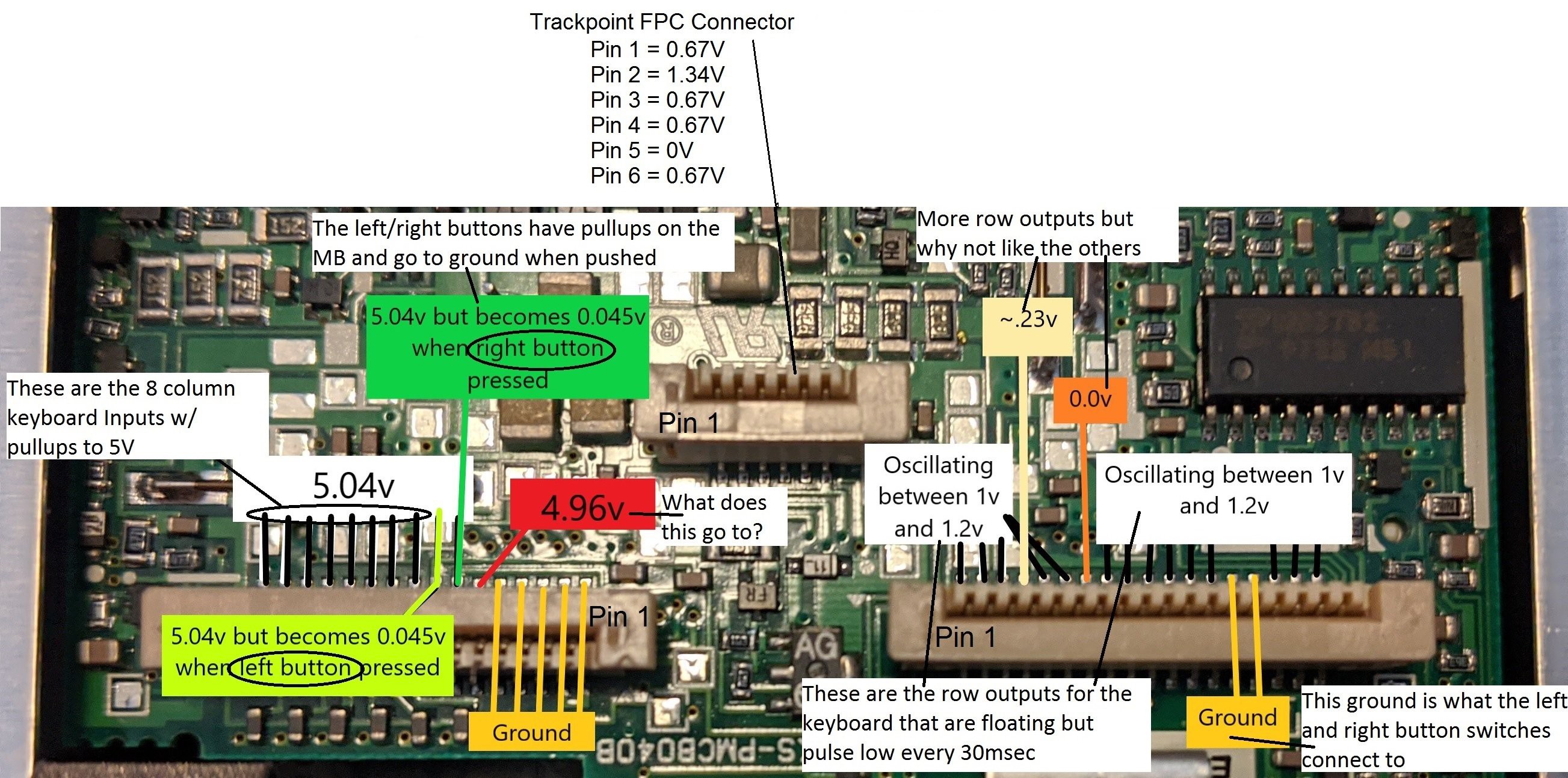
Laptop Testing: Brian and I teamed up for this project so we could share in the fun. We couldn't find a schematic for this laptop so resistance and voltage measurements were used to figure out the connections to the 3 FPC cables. Brian took the following measurements with the FPC cables installed in the 380ED laptop.

16 pin FPC connector - The first 5 FPC pins are strapped to ground to identify the keyboard as a US language configuration. Pin 6 is for the Fn key. The right and left trackpoint buttons on pins 7 and 8 are pulled up to 5 volts and go to ground when the buttons are pressed. Pins 9 thru 16 are the 8 columns for the key matrix and are pulled up to 5 volts.

18 pin FPC connector - Pins 1 thru 3 and 6 thru 18 are the key matrix rows that are each pulsed low so the columns can be scanned for a closed switch. 

6 pin FPC connector - Pin 2 is power and pin 5 is ground. Switching to resistance measurements showed that pins 3 and 6 are tied together and pins 1 and 4 are tied together. These two sets of pins go to the X and Y strain gauge variable resistors. 
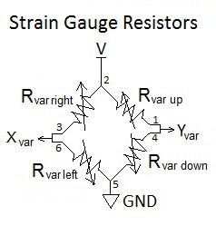
Crude Trackpoint Testing: A crude test board was created with an FPC connector and jumpers to a Teensy 3.2.
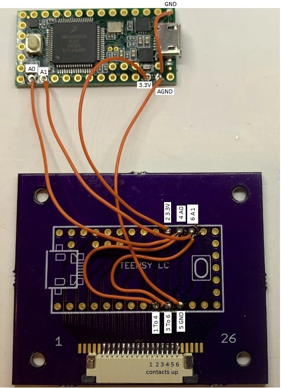
FPC Pin 2 goes to Teensy 3.3 volts. Pin 5 goes to Teensy ground. Pins 3 and 6 go to Teensy ADC A1 and pins 1 and 4 to Teensy ADC A0.   Resistance measurements show the individual strain gauge resistors are 352Ω when at rest. If the trackpoint is forced hard left, right, up, or down, the resistance will change about 1Ω. When powered with 3.3 volts, the voltage divider will only change ± 4mV. I expected this would be difficult to reliably detect with the Teensy but gave it a try anyway. I used code I had previously developed for converting the pointing stick (aka trackpoint) from a Dell D630 to USB. The Dell trackpoint uses 4 KΩ strain gauge resistors that cause a change of ± 30mV which is a lot easier to detect. The code reads the X and Y voltages at startup and saves these as the “at-rest” values. There is a dead zone around the at-rest values so noise doesn’t cause unwanted cursor movement. The Thinkpad trackpoint was able to move the cursor with this code but too much force was needed. Reducing the dead zone allowed less force but noise would move the cursor when at rest.

Instrumentation Amplifier: The standard method for reading a strain gauge is to use an instrumentation amplifier. I chose to use the AD8236 because it’s low cost, works on a single supply and has a reference pin for offsetting the output. The schematic for the X channel amplifier is shown below. The Y channel is the same. The LM358 Dual Op Amp provides a low impedance 1 volt DC reference voltage to each AD8236. This raises the output up to 1 volt when the inputs are balanced in order to operate from a single 3.3 volt supply. The gain of the AD8236 is set to 47 with a 10KΩ resistor. The 10KΩ potentiometer provides the fine tuning to set the minus input to the exact same voltage as the positive input when the strain gauge is at rest.
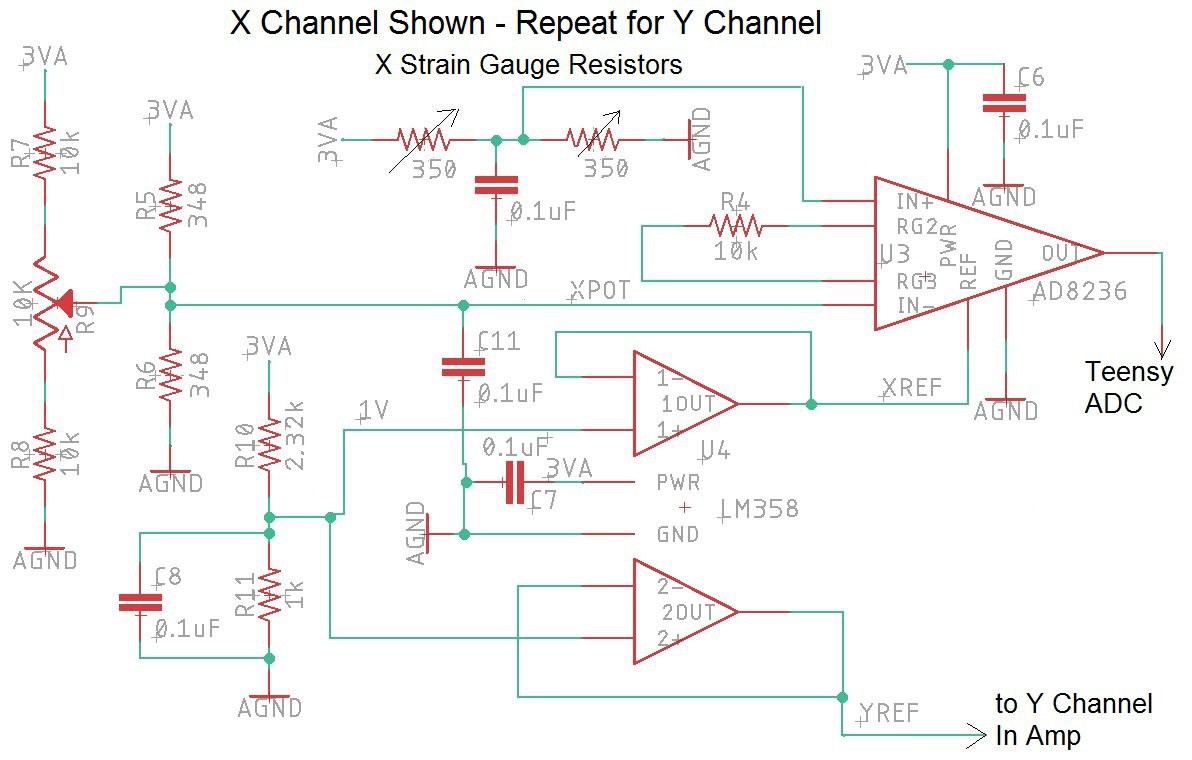
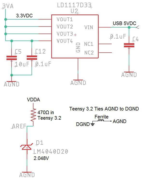
An LM4040D20 shunt style voltage reference is used on the Teensy 3.2 AREF input to give 2.048V for the ADC reference instead of the standard 3.3 volt reference (see schematic below). The 13 usable bits of the Teensy ADC will span 2.048V instead of 3.3 volts. This changes the resolution to 0.25mv/bit instead of 0.4mv/bit. An LD1117A linear regulator is used to drop the USB 5 volts down to 3.3 volts for powering the trackpoint circuit. This was done instead of using the Teensy’s 3.3 volt regulator in order to reduce the digital noise in the amplifiers. Note that the Teensy ties analog ground to digital ground with an inductor as shown below.
Breadboard Circuit: The AD8236 is not available in a DIP but I really wanted to make sure the circuit would work before getting a board fabricated by OSH Park. The breadboard shown below was a test of my soldering skills but after...

Read more »

Thinkpad380ED_2020-09-30.zip

Zipped gerber layout files for fabrication at JLCPCB.com

Zip Archive - 198.22 kB - 09/30/2020 at 17:51

Download

Thinkpad380ED.sch

Eagle Schematic file

sch - 295.17 kB - 05/05/2020 at 22:48

Download

Thinkpad380ED.brd

Eagle layout file

brd - 124.74 kB - 05/05/2020 at 22:47

Download

  • 11 × Digikey 399-1099-1-ND 0.1µF ±20% 16V Ceramic Capacitor X7R 0603
  • 1 × Digikey 490-14372-1-ND 10µF ±10% 10V Ceramic Capacitor X5R 0603
  • 1 × Digikey P2.32KDBCT-ND 2.32 KOhms ±0.1% 1/10W Chip Resistor 0603
  • 1 × Digikey P1.0KDBCT-ND 1 KOhms ±0.1% 1/10W Chip Resistor 0603
  • 1 × Digikey 1528-2385-ND Teensy 3.2 with unsoldered header pins

View all 18 components

  • 1
    Solder the SMD's

    There are 3 ways to solder the surface mount components:

    Soldering Iron - Put some flux on the surface mount pads for the component you're working on. Melt a small amount of solder directly on a clean, small tip. Hold the component down on the board with tweezers while touching the soldering iron tip to each leg/pad long enough for the solder to spread. For the IC's and FPC connectors with multiple legs, slide the iron tip from leg to leg. Add more solder to the tip as needed.

    Hot Air Rework Station - Put some solder paste on the PCB pads. Place the components on the pads.  Direct the hot air on the parts long enough to melt the paste. Try to blow the air directly down on the board (not at an angle). Reduce the airflow if the parts are not staying in place. 

    Reflow Oven - Put solder paste on all the surface mount pads and then place each SMD component on the pads. Place the circuit board in the reflow oven and program the oven to the appropriate temperature profile for your solder paste.

  • 2
    Fix Any Solder Problems

    Do a visual inspection with a magnifying glass, looking for any solder problems such as IC legs that are shorted together or pads that did not get enough solder. Use an ohm meter with stick pin probes that are small enough to allow you to check for shorts on the adjacent legs of all the IC’s and FPC connectors. Verify there are no power to ground shorts. Fix any shorts by applying flux and using solder wick. You may need to add back a little solder if the wick removed too much.

  • 3
    Install the Teensy 3.2 and the Potentiometers

    Use a Teensy 3.2 with header pins or solder your own header pins taking care to get them perfectly straight. The surface mount connections on the back side of the Teensy can be done with flying leads but a 2 x 7 SMD header is a lot easier to install. You'll need a long, skinny tip so your soldering iron can reach the pads. The alignment of the header is difficult to eye-ball. Use a small prototyping board with standard 0.1” hole spacing that can keep the header in position while you solder the pads on each end. You can use header pins or wires to attach Teensy pads AREF, A10, A11, A14, and GND2. The other Teensy pads are not used but can be connected to the board if you want (it looks better).

    Solder both 10K potentiometers to the board (in the same orientation).

View all 5 instructions

Enjoy this project?

Share

Discussions

Steve wrote 02/11/2024 at 14:11 point

I have a couple later-model Thinkpads (P5x series) with dead mainboards just hanging around taking up space. Do you think this could work for a Lenovo-era trackpad & keyboard ?

  Are you sure? yes | no

Frank Adams wrote 02/11/2024 at 16:05 point

I watched a Lenovo Thinkpad P50/P51 keyboard replacement video to see the FPC cables. The keyboard FPC cable should be easy to decode and turn into a USB keyboard using my Keyboard Instructable

  Are you sure? yes | no

Frank Adams wrote 02/11/2024 at 16:11 point

Instructable is here https://www.instructables.com/How-to-Make-a-USB-Laptop-Keyboard-Controller/
The trackpoint has its own FPC cable and you'll need to figure out how it's wired. Since you have the motherboard, you can use it to figure out where power and ground pins are located. The X/Y signals are probably sent over a clock/data bus using PS/2 protocol. My Instructable shows how to code for this.

  Are you sure? yes | no

Nickie wrote 06/18/2022 at 12:07 point

hi! 

i'm in the process of trying to retrofit a thinkpad 765L, the 760 series have an extremely similar ribbon cable layout ( 18+16pins, and trackpoint 6pin) do you think your board has good chances of being useable as-is on those?
( i mean hardware-wise at least, even if some remapping is needed )

i can solder SMDs and handle a multimeter but the intricacies of keyboard matrices are kind of out of my reach :D

  Are you sure? yes | no

Frank Adams wrote 08/08/2022 at 17:09 point

Hello Nickie, I think there is a good chance that your Thinkpad 765L would work with this board. Besides doing a thorough visual check, I would suggest you do a lot of ohm meter checks, especially with the trackpoint signals to make sure they match my schematic. Good Luck.

  Are you sure? yes | no

Stephen Arsenault wrote 07/21/2020 at 03:30 point

Hey @Brian Chan & @Frank Adams, here's the case I came up with — let me know what you think! https://www.thingiverse.com/thing:4548311

  Are you sure? yes | no

Frank Adams wrote 07/22/2020 at 14:14 point

Thanks Stephen, the files look great!

I've added links to them at all my sites.

  Are you sure? yes | no

micl wrote 01/21/2023 at 22:28 point

Thank you for this. Super useful to have, even as a mechanical reference.

  Are you sure? yes | no

[deleted]

[this comment has been deleted]

Frank Adams wrote 06/30/2020 at 23:04 point

It is possible to add a SPI bus display to this project. It could show the key that is currently pressed, trackpoint data or buttons, CAPS, NUM, and SCROLL LOCK status plus the analog voltage on spare ADC inputs A12, A13, and A14. These analog inputs could be wired to temperature sensors, battery voltages or anything else you can think of. Another use for the display is to show which key map is currently selected. This assumes you have added additional arrays of key maps to the code. 

SPI bus pins 10, 11, and 12, on the Teensy are currently wired to the keyboard matrix so leave out header pins at 10, 11, 12, 13, 15, 16, and 17. The matrix can be wired over to spare I/O pins 17, 16, and 15 as follows;

Teensy 17 to board 10, Teensy 16 to board 11, Teensy 15 to board 12, then modify the software to use these new I/O pins for scanning the keyboard.

Connect to the SPI bus display as follows:

Teensy 10 to LCD SS pin, Teensy 13 to LCD SCLK pin, Teensy 11 to LCD MOSI pin, Teensy 12 to LCD MISO pin, then add the software to use the SPI bus to drive the display.   
If you or anyone else does this modification, let us know how it worked out.

  Are you sure? yes | no

Frank Adams wrote 06/21/2020 at 16:03 point

Brian Chan has used the keyboard and trackpoint from this project to make a KVM. His guide shows how to modify the case and add a video converter card. The Hackaday.IO project is at: https://hackaday.io/project/172327-thinkpad-380ed-to-kvm-conversion

  Are you sure? yes | no

yeungkh wrote 05/29/2020 at 19:04 point

Inspired by your guide (also the one from instructable), I manage to use 2x MCP23017 expanders to expands the pins that i needed for the keyboard scanning. Also such IC has an interrupt trigger so I would not miss any possible stroke. In this way, I could use a cheaper 32u4 without any lost of performance. Now i am using it as a KVM on my old dell n4030. Additionally i use the modified laptop as portable external monitor, with the possibility to connect through usb for the onboard KVM. If you are interested in my approach with the MCP, please let me know!

  Are you sure? yes | no

Frank Adams wrote 05/30/2020 at 07:14 point

Well done on your KVM. I have a board designed and fab'ed that uses two MCP23018 expanders but am backed up with other projects and haven't assembled it yet. Hopefully I'll get to it this summer.  

  Are you sure? yes | no

gtracy wrote 05/26/2020 at 20:57 point

I have a Thinkpad A21 which I still use with Ubuntu loaded on it. Battery life sucks but heh, it's still a great laptop just a little slow.......Keyboard and trackball still work!! Love it.

  Are you sure? yes | no

Andy Pratt wrote 05/16/2020 at 06:07 point

A very interesting project repurposing old but good hardware. Do you have any demos of it working yet?

  Are you sure? yes | no

Frank Adams wrote 05/17/2020 at 08:02 point

I've updated the project with the test results. It's working great.

  Are you sure? yes | no

Andy Pratt wrote 05/18/2020 at 12:22 point

Nice, did you do anything about a casing for it?

  Are you sure? yes | no

Stephen Arsenault wrote 05/26/2020 at 23:31 point

@Frank Adams I would be happy to contribute the 3D designs for an enclosure to this project. If you're interested then I will need accurate dimensions — if you can find a very accurate 3D model of the most popular keyboard or send me one to use for dimensions I can get started.

  Are you sure? yes | no

Brian Chan wrote 05/28/2020 at 03:01 point

@Stephen sure, that would be cool!

  Are you sure? yes | no

Stephen Arsenault wrote 06/29/2020 at 19:43 point

hey @Frank Adams & @Brian Chan, I just wanted to bump this comment to let you know I'm still available to help out with an enclosure but will need a physical copy of the keypad & hardware or accurate 3D models in order to start.

  Are you sure? yes | no

Brian Chan wrote 06/30/2020 at 17:42 point

@Stephen Sure, just sent you a message

  Are you sure? yes | no

Brian Chan wrote 05/18/2020 at 20:15 point

We do not have a custom case for it at the moment, but are reusing the laptop case the keyboard is from. The lid can be taken off to remove excess bulk and weight

  Are you sure? yes | no

Frank Adams wrote 05/24/2020 at 03:05 point

I have uploaded a Youtube video so you can see the keyboard and trackpoint in operation. https://www.youtube.com/watch?v=WGSg1ky4UUs&feature=youtu.be

  Are you sure? yes | no

Similar Projects

Does this project spark your interest?

Become a member to follow this project and never miss any updates