Taylor Schweizer
-
Reverse Engineering Motor Signal Board
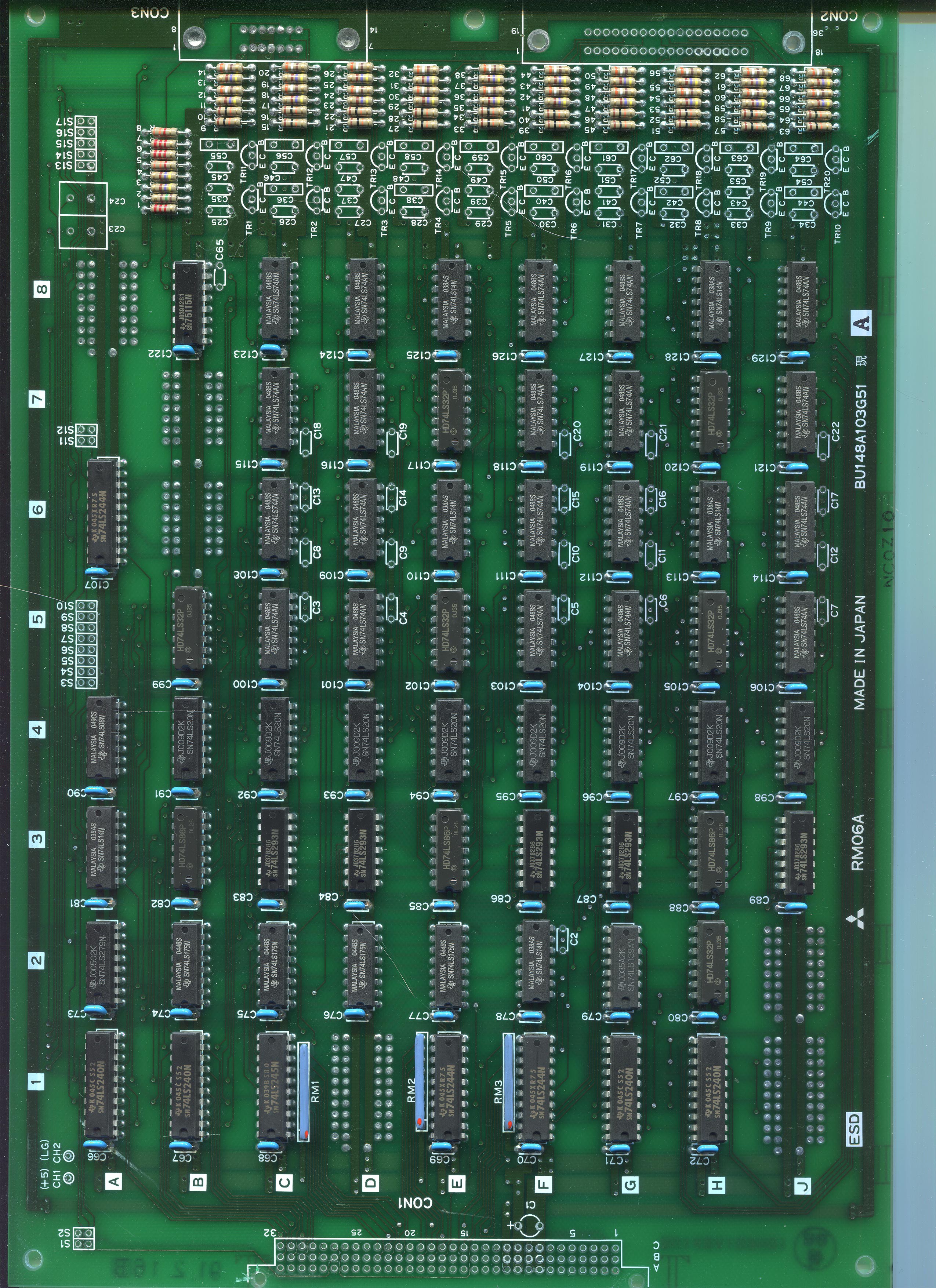
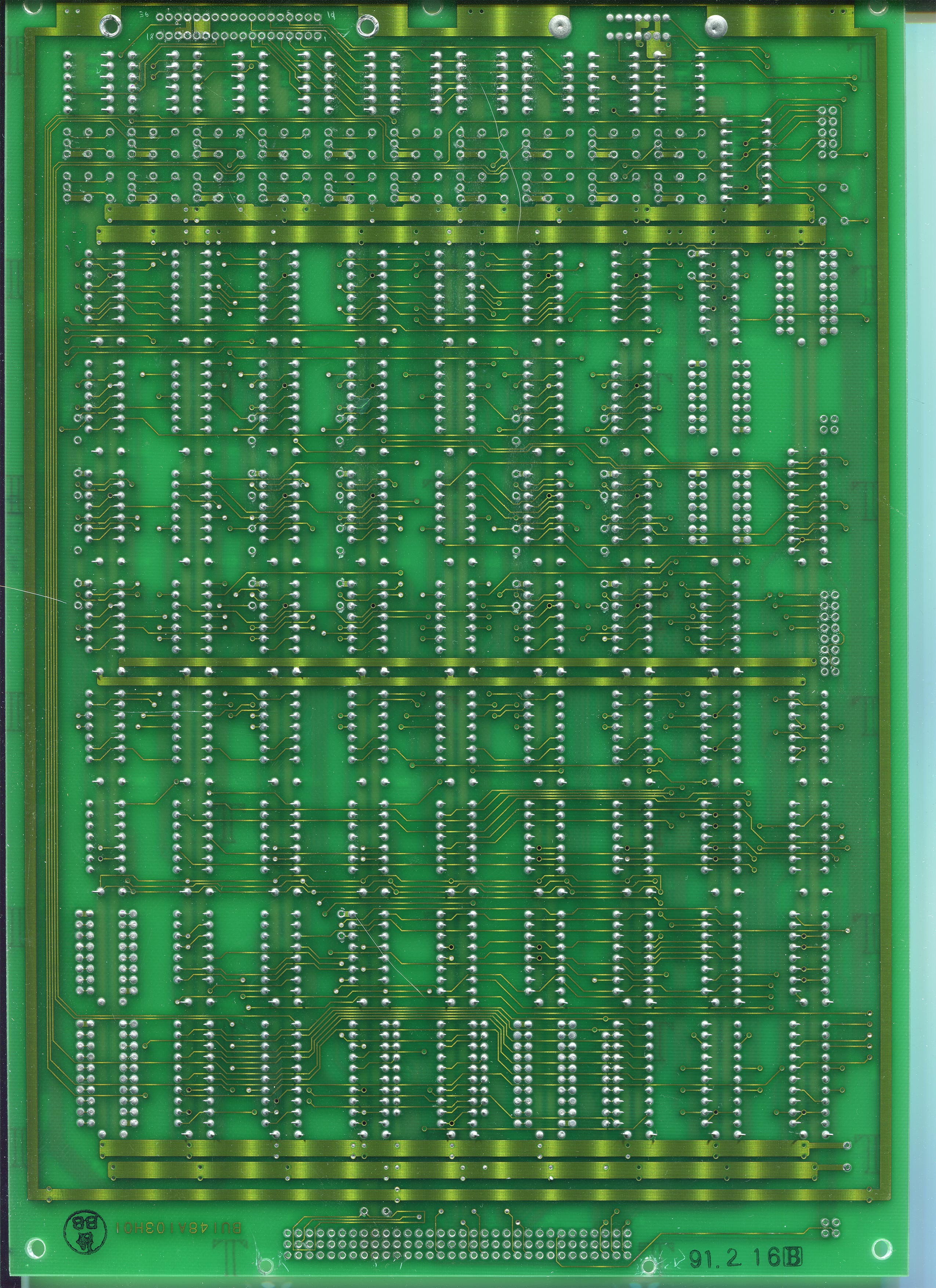
05/15/2020 at 20:36 • 0 commentsI've written a bit about this on my website https://learn-cnc.com/reverse-engineering-pcbs/ and I'm going to use the same flatbed scanner for these.
Unfortunately some of the connectors and stuff on these parts were so large that the flatbed scanner couldn't image the traces, so I had to remove them. The scans of each side were about 1.6 GB each, so I downsampled and converted them to a PNG (they were a 24 bit BMP) which reduced them to about 80 MB each. Still large, but workable.
Here's some sample scans from the Motor Signal board (these have been further downsampled and compressed to a JPG, about 2 MB each):
![]()
![]()
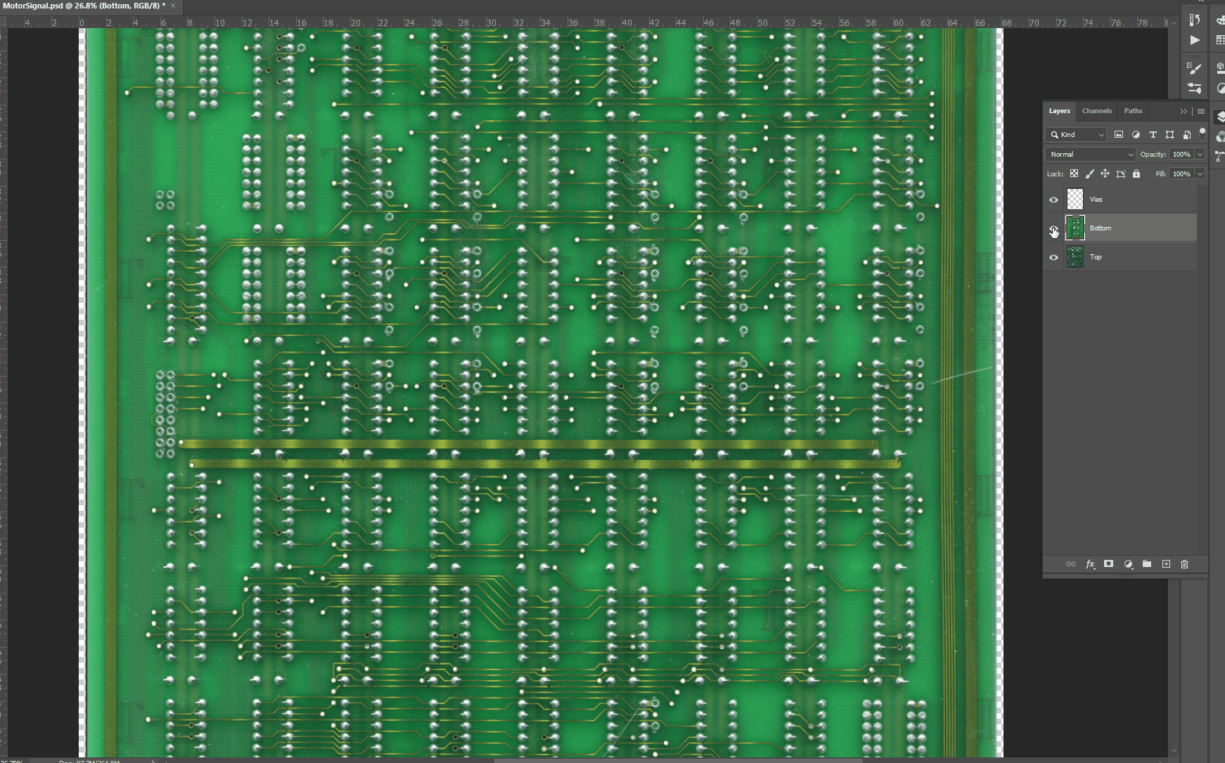
I then use the perspective warp and crop tool in Photoshop to square up each image. This makes aligning them much easier. Then I make a new layer just for holes and vias so I can align the images using the warp tool.
![]()
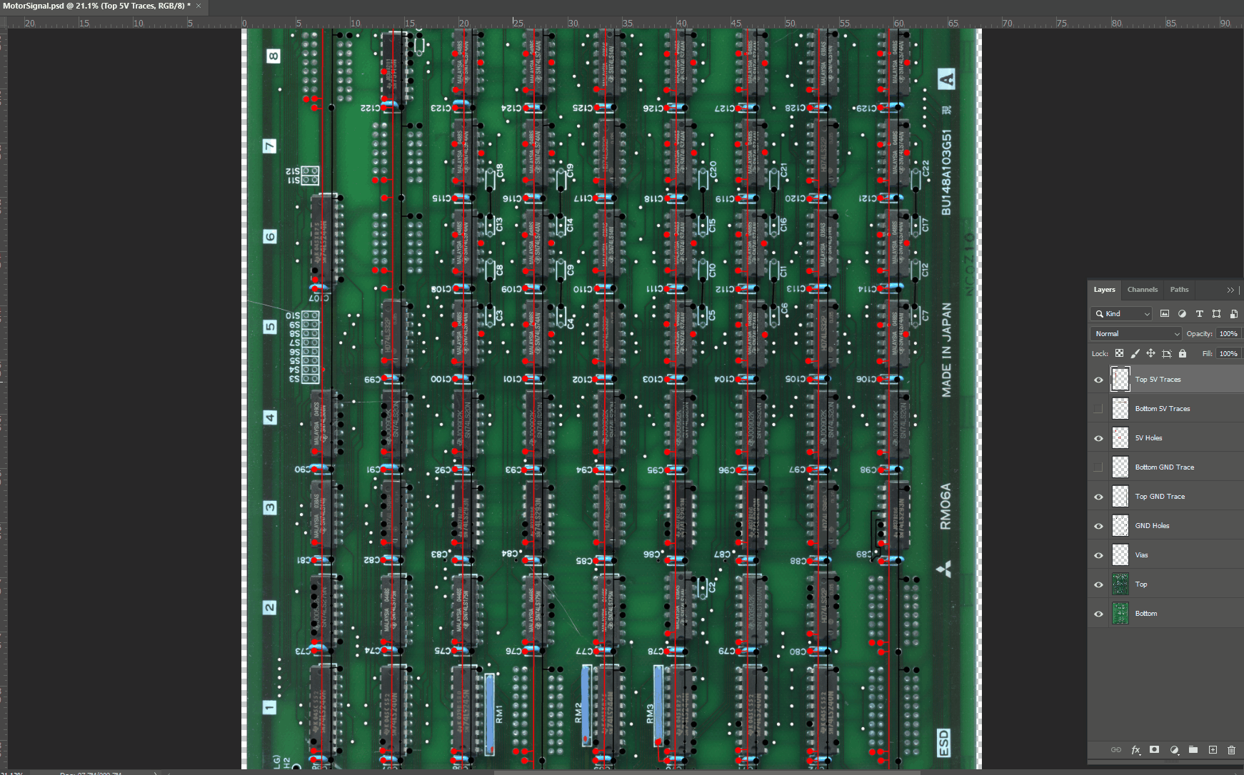
I start by finding the ground and power rails since those are the easiest to find and cover the largest amount of traces and holes. On a smaller board I would remove every component, but I'm only planning on reverse engineering a single encoder channel since it looks like this is just a repeated circuit so I don't need all traces.
![]()
-
Drive Unit Overview
05/12/2020 at 21:32 • 0 commentsRV-M1 Drive Unit with cover removedThe drive unit is certainly an old piece of equipment, and part of my motivation in this project is to see just how much smaller I can make a new drive unit with modern electronics. Despite the size, it is still a pretty straightforward controller.
The unit itself consists of a power supply section and a distribution board. There are four additional boards that plug into the back of the unit - these provide the kinematics, programming, serial interface, motor drivers and motor feedback.
RV-M1 Drive Unit with cover removed:

RV-M1 Drive Unit Top View:

You can see the large transformer and heatsink for the power supplies in the pictures above. The four boards mentioned are on the right. Below are some pictures of the distribution board with the front panel of the drive unit removed.


Above: Back facing side of the distribution board The distribution board shown in the images above basically just connects the four plugin boards together, as well as the power supplies and the buttons/lights on the front of the drive unit.
Now for some pictures of the plugin cards. First, a picture of the back of the drive unit showing the layout of the cards:

Below is the card with the main processor and memory, as well as the serial communication.

Below is the External IO and Teaching Box card.

Below is the Motor Signal card. This takes in the limit switches and quadrature encoders from the arm.

Below is the motor and brake power card. This provides power to the motors and electromagnetic brakes. Unfortunately I think this is a 4 layer PCB, although it does look like it is only power and ground on the middle layers.

I will be splitting each board up into its own log.
Reviving and Reverse Engineering an Old Robot Arm
A full reverse engineering and rebuild of a Mitsubishi Movemaster robotic arm