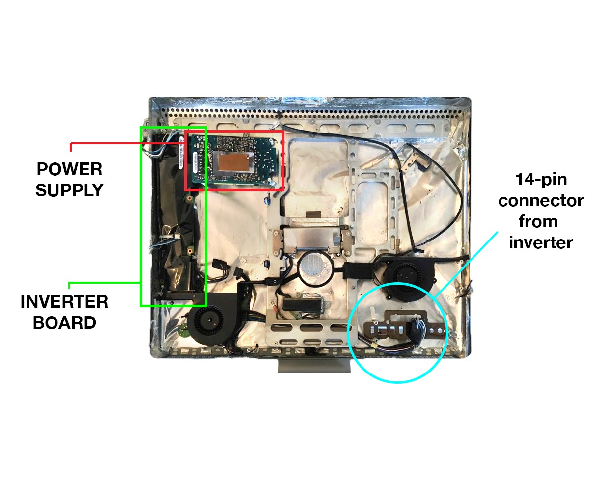
This first project log entry comes after I've started the project, so I'll start by outlining where the project is at the moment and what the main challenges are. I've removed all the components from inside the computer except for the power supply, the inverter board, and the long snake of cables that connects the inverter board to the logic board. The fans, speakers, logic board, hard drive, and optical drive are all sitting in a pretty pile next to my workbench, likely destined for the e-waste bin (though I might reinstall a fan and the speakers if the project is successful).

The two main challenges for this project are 1) powering the monitor, and 2) retro-fitting the monitor cable to a female HDMI connector.
1) Powering the monitor
This process is not intuitive, and the only reason I know about it is from a few brave souls on the internet who have somehow figured out how to do this, most notably in this series of forum posts. On this model of iMac the power supply feeds into an inverter board, which in turn feeds the main logic board with a long snake of cables that terminate in a 14-pin connector. Power for the LCD backlight comes from four cable clusters coming off the inverter board which need to be somehow activated (more on this in a moment). The data for the LCD (and a bit of power) comes from the logic board. For this project we will continue using the inverter board to power the LCD backlight through some trickery that allows us to disregard the logic board entirely. If we look at the back side of the logic board (which we have removed and discarded) you can see some of the pinout information for the cables coming from the inverter. They are printed on the board opposite the female socket:

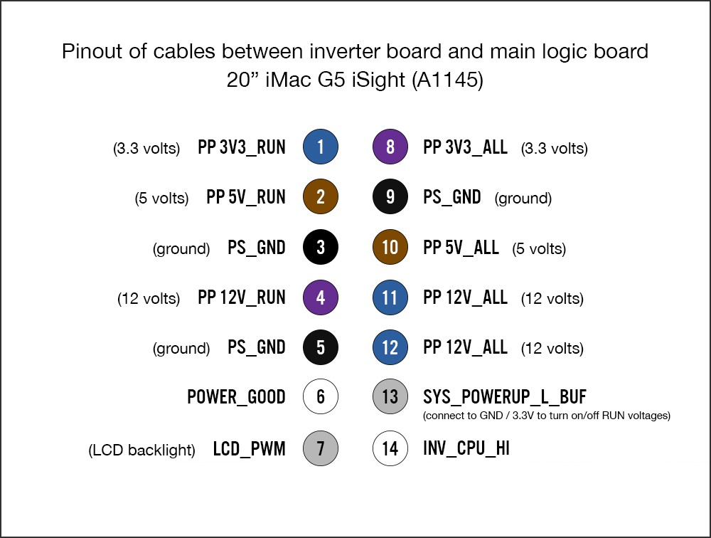
Working from that and other assorted sources floating around the internet, I've cobbled this pinout diagram:

These pin numbers are arbitrary (the connector isn't labelled, so I assigned my own numbers). All of the power pins marked "ALL" are hot whenever the computer is plugged into mains power. The RUN power pins are floating: they can be activated by tying Pin 13 low (to GND), and deactivated by tying pin 13 high (to 3V3_ALL). Tying LCD_PWM high (to 3.3V) activates the LCD backlight. I'm not yet sure what the function is for POWER_GOOD and INV_CPU_HI, or whether they are relevant to our specific mission. The YouTube user "3beltwesty" has a wonderful series of short videos demonstrating some of this.
I suspect that this process of activating and deactivating the RUN voltages is how the user will power the monitor on/off. I just need to figure out how to put in a switch in a way that is user friendly. I welcome any and all advice regarding this question.
2) Retrofitting the LCD cable for HDMI
This part of the project definitely feels like I'm out on the frontier, as I haven't been able to find nearly as much information as I would like about the LCD monitor cable pinout, and the information I do have is sometimes contradictory. In short, a cable from the logic board feeds the LCD via a 30-pin connector on the back of the monitor. The connector at the logic board end appears to be one of Apple's obscure proprietary connectors. Our objective is to hack the connector at the end of the cable (the opposite end from the 30-pin LCD connector) and affix a female HDMI connector in its place. We will then mount this female HDMI so that it protrudes through the back of the computer case for user access.
I found a very helpful forum post with a chart of the pinout of the connector on the monitor and how it would convert to a DVI connector, but there are inconsistencies between that chart and the 30-pin connector on my machine (several of the wires are a different color, and somehow there is an extra wire coming from my connector that isn't accounted for in the chart). Here is a photo of the 30-pin connector that attaches to the LCD on my machine:
After peeling back some of the outer layers of the other connector (where the female HDMI hub will go), I was able to uncover a bit more information:
The labeling on this connector answers questions about some of the mystery wires, all of which are grouped together either as GND or 3.3V. But 3.3V seems strange, firstly because of the size of the monitor, and even more so because the chart I had found online lists these pins as 12V. So clearly there's some information I'm missing. I would welcome thoughts advice from anyone who has experience with this. Is VCC to the monitor really only 3.3V (as marked on the small connector)? Or is it 12V, as noted in several of the posts I've found online? This information is important to get right, as there is circuitry inside the monitor that could be damaged.
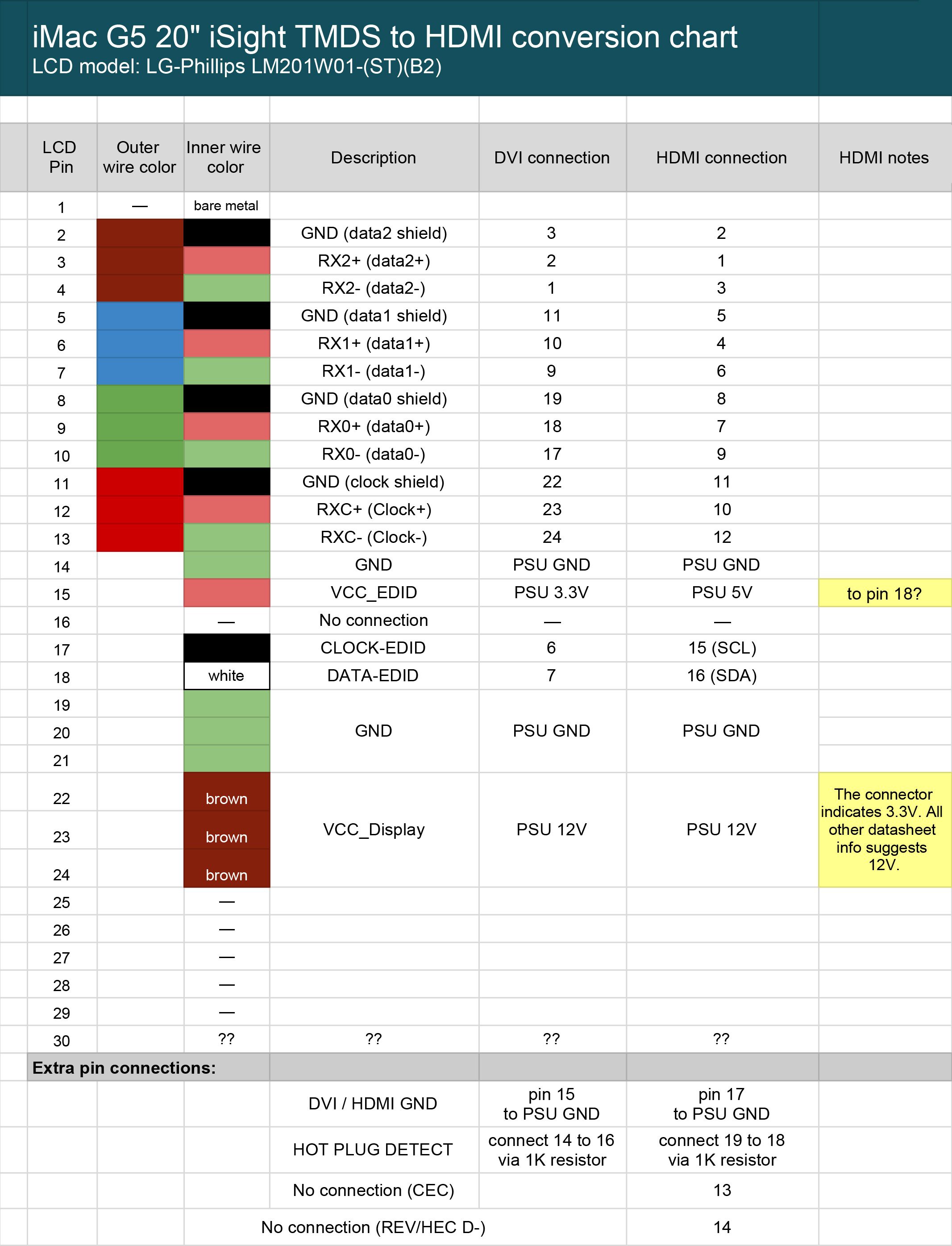
Borrowing from this beautiful LCD-to-DVI conversion chart I found online, I've plugged in my own values for what I *think* is a correct pinout for HDMI. I've marked the questionable information in yellow. Please bear in mind that this is untested:
UPDATED to include data from the following project log

I'm going to stop here for now. Hoping some of you can chime in regarding my questions in in the above HDMI pinout chart.
My hope is that even if this project fails, it will at least help a few people down the road who are attempting a similar mod.
 Thomas
Discussions
Become a Hackaday.io Member
Create an account to leave a comment. Already have an account? Log In.