Abel Rodriguez
-
USB communication between the boardgame and the GamMa program
02/14/2025 at 10:30 • 0 commentsI’m already working again in the project after a loooong pause, but with renewed strength. I’ve mounted the Helvetios boardgame in a trainer that I made some time ago: a briefcase with a RaspberryPi, an LCD screen, some batteries and a power supply system. This way I can develop the software to control the boardgame without connecting a computer. The briefcase project can be checked in my other projects.
![]()
In this trainer I’m developing the application GamMa (Game Master) to manage the electronic boardgame. Its a C++ application, not because it’s needed but as a way to improve my skills in this language, that I don’t usually use in my projects. It think could be done in C or Python without issues. This program will manage the communication with the boardgame and to work as an interface between the player and virtual ‘Game Master’. This Game Master will be the code that will guide the player in the actions to take in each game phase (move, defend, attack, collect, mine, trade, etc…) and will show the consequence of these actions. That will be done using a screen where it will show the options of each phase and also in the board by illuminating the cells affected by the range, direction or target selected by the action. The player also could select the action with the selection, accept and cancel buttons, and has a navigation panel with 6 buttons to select the range or direction of this action. A simplified version of the interface will look like this:
![]()
Right now this program only communicates by USB with the boardgame, being able to control the color of the cells and read if there is a piece in any cell. It will also manage the flow of the game between various players and decide the result of the selected actions of each player based in some prearranged rules, assigning by the parameters of each piece or player as speed, energy, strength, range, shield, load capacity, goods pricing, etc…
It is intended that all text, actions and rules are programmable and editable externally to the code, so that the games can be fully adapted to a story and turn the board into a collaborative playground or battle as set in the configuration by the user without programming knowledge. This way we can set up multiple games on each board, totally changing the story and the objectives of the game, being able to be a game of asteroid mining, resource gathering, tank battles, ships, boats, soldiers, orcs, space marines…, or simply abstract logic games or puzzles. Everything is up to my ability to program the game logic and the editing system of menus, phases and rules.
The code of this application uses the HidAPI library to communicate with the board, with a more than acceptable speed for the intended application. The STM32F103 microcontroller is capable of handling a 12Mbits FS USB connection, but there is a lot of overhead in the USB protocol and the effective speed is considerably lower. However, based on tests it is more than sufficient to transmit a cell status update. The animations will be programmed and executed on the microcontroller side, leaving free the communications for state updates (cell color and animation, piece detection in each cell). This application will be available in my Github, so it can be used by anyone as a base to develop other interfaces or modify it to include other functionalities.
The representation of the interface is made with GTK3, which is light enough to run on any system, as well as the C++ code will also be fast enough without needing much processing power or memory, if it were developed in Python or QT surely the resource consumption would be higher. A simple GTK interface will be developed so that the board can be connected to any Linux computer or embedded system, but the goal is to recreate a hardware interface for each player on the board. That is: various OLED screens of 128×64 pixels, if required a larger one will be used, a button panel for menu and board navigation, a led bar that identifies the turn or status of each player and some leds that identify in which phase of his turn he is:
![]()
This way the board is independent of a computer, and using a low-resource embedded system such as the Raspberry Pi Zero 2W would be sufficient to control several of these player interfaces for the same board. And with more advanced development, this embedded system can act as a rival to play solo games, connect to the internet to play with multiple boards and remote games with other players. It would also allow a much more advanced game status interface through a web server and show the development or even to interact with the board from a mobile device with a player interface via web.
In addition to what is described for each player, it is intended to include an NFC reader to identify the tokens (meeples, ships, soldier, etc.) of each player or to read cards. In the manufacture of the tokens, an NFC tag such as the Murata micro tag can be inserted. In this way the token itself can gain skills or change characteristics, and this evolution can be registered in the token itself, being able to use these improvements in following games. It has also been thought to include a small speaker that can generate some sound effects of resolution of the actions (battle won/lost, resource obtained/spent, movement, etc…).And here is a small demo of the USB communication with the board, all data of color is sent from the app in the raspberry. Sorry for the illumination, it's not easy to record leds with low ambient light:
-
Mounting the prototype of the 91 cells electronic board game
01/01/2023 at 15:38 • 0 commentsFinally I’ve gathered all the components and mounted the first full prototype of the board game (I already did some test previously to validate the SPI led drivers in First prototype of the electronic board game Helvetios). The component shortage has delayed the mounting by 6 months until I’ve got some critical components, mainly the led driver TLC5947 and the DC/DC regulator TPS561201.
Initially I contacted some pcb companies from China to fully build the prototypes, but the cost of the components at the start of 2022 was way too much. So I ordered only the PCB and the bottom stencil in JLCPCB, and then I gathered the components until have them all so I could build the circuits by myself.
I did the mounting by hand (in the absence of an SMD oven as the I used for the circuits in the LifeLinker), using soldering paste, a hot air soldering station and a lot of patience. To solder the bottom side I used a stencil so it’s were there are more integrated circuits and some with thermal pads like the led driver. This way the solder paste distribution would be much better.
The circuit was designed to be content in size so the first prototypes would be more economical due the pcb price and the necessary acrylic sheets to make the led difusor and the cell separator. This way we could program all the firmware to control the leds and the USB communication. The next designs will follow the concept of row circuits as explained in Helvetios. This way we could make boards with more and bigger cells.
Some pictures of the mounting process:
![Helvetios circuits]()
The circuits as they arrived. ![pads detail]()
The size of the pads for the led drivers is really small. ![fixed circuit]()
Fixed circuit to use the stencil and apply the solder paste. ![Components mounted]()
Components mounted ready to solder with the hot air station. To start the prototype I used a development board NUCLEO-F103RB, which I already used in First prototype of the electronic board game Helvetios. This time I used the development board to program the circuit, using the connector that allows to program other circuit by using the SWD communication. This way I could connect to the electronic board game and debug the code for the led drivers and the Hall sensors:
![Firmware development setup]()
Firmware development setup Besides the development board I used a little 8 channel 24MHz logic analyzer. With this device and the software Pulseview from the Open Source project Sigrok is easy to see which signals are generating and check the correct addressing of the led drivers. Also you could decode some protocols as SPI and I2C, and is very useful to determine the refresh speed of the system.
![]()
Pulseview software When testing the code I also tried some led diffusers:
![]()
Acrylic Diffuser Opal Ice 3mm ![]()
Acrylic Diffuser 33% 2mm And finally a video showing the cell detection and some color examples:
-
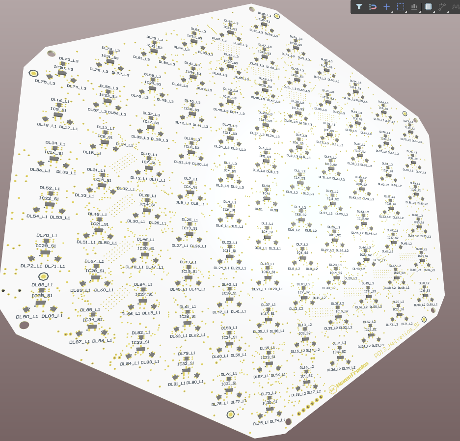
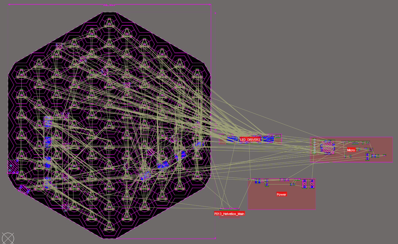
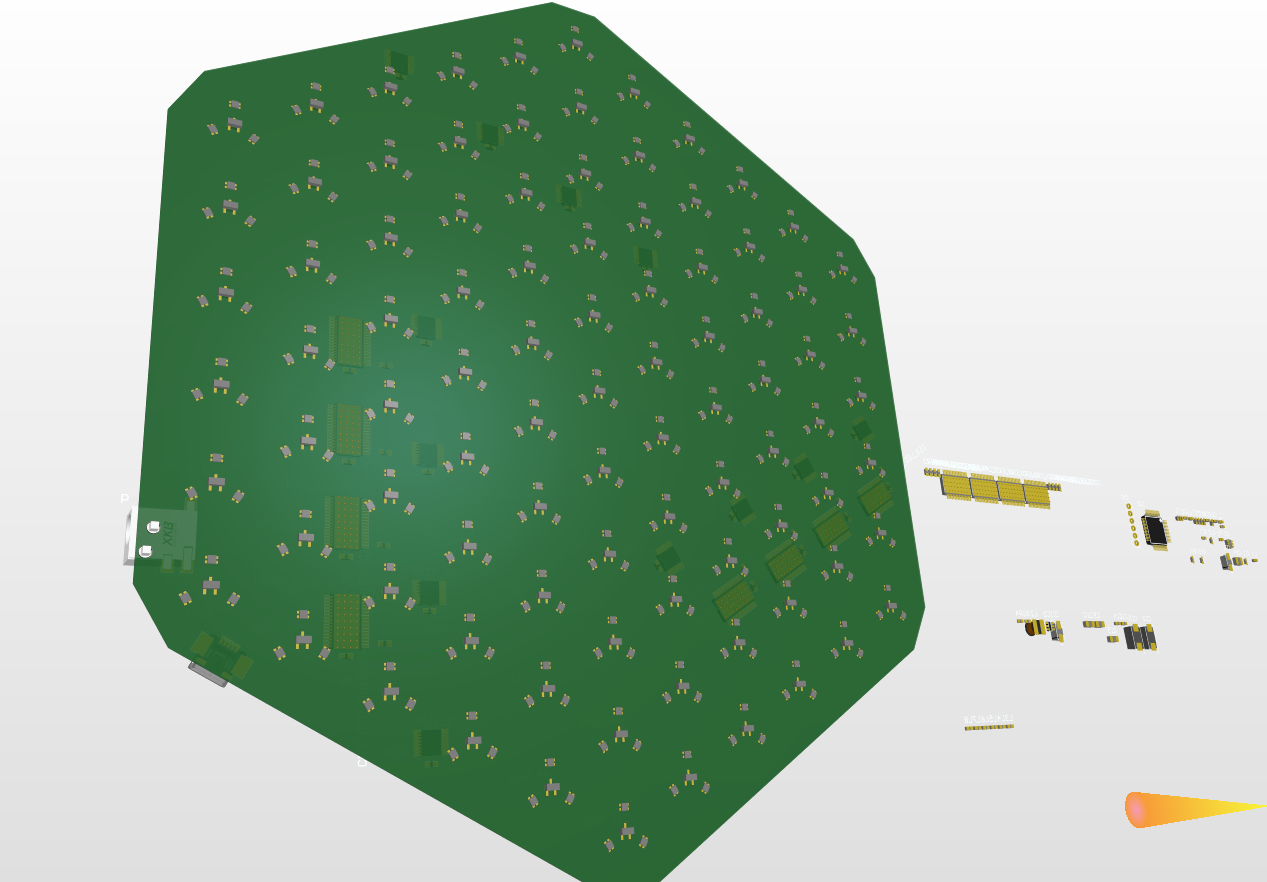
Finished the first PCB design of the Helvetios boardgame
12/27/2021 at 13:17 • 0 commentsThese last months I’ve been finishing the design of what will be the first circuit of the electronic boardgame Helvetios. It has been a little slow process, due doing it in my free time but mostly due doing it in only one circuit to save cost. In later designs I will continue with the concept of circuits of rows of cells, connected between them. This will allow bigger boards and with more and bigger cells.
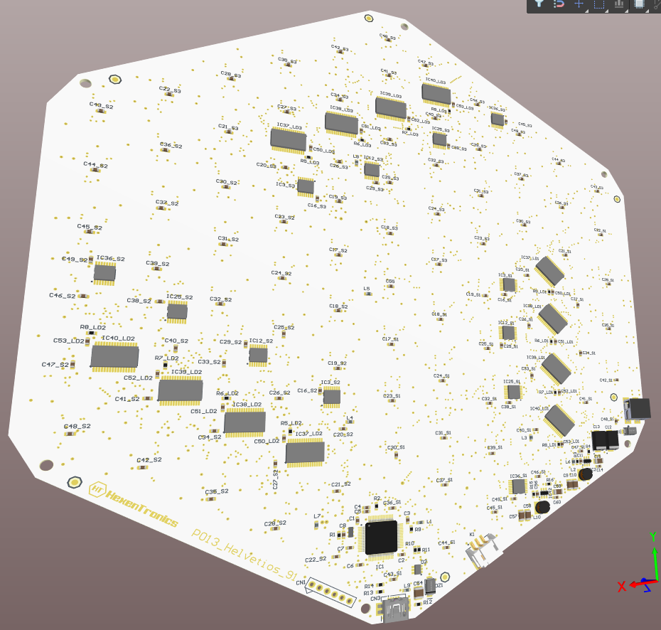
The design of this boardgame have 91 cells, and it will be used to develop the control firmware. This software will manage the RGB lightning of the cells, the magnetic Hall sensors and the USB communication with the game master circuit.
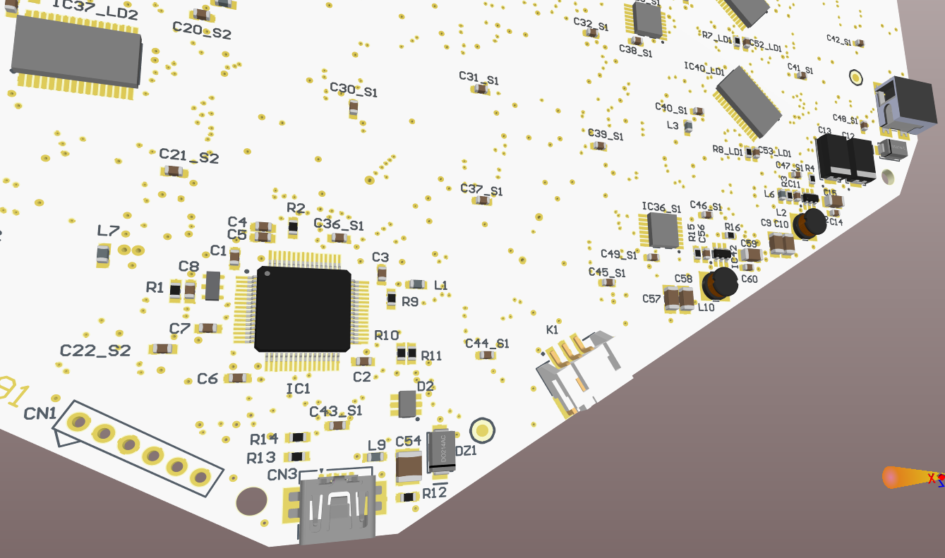
In the bottom layer there are the connectors. It has an input power supply connector, a micro USB to communicate with the game master circuit, and a power supply output connector to supply this other circuit.
Now starts the manufacturing process of the circuit, that will also be complicated due the lack of component supply situation. It’s very possible that I could not get some critical components like the led drivers or the microcontroller in all this year 2022. The lead time is 2023 for some of them. Also the fact that the circuit has components in both sides implies that not any factory could mount them, it needs to reflow process to solder all the components.
I will use this this board circuit assembly time to develop the game master circuit, and make designs of the enclosure to house the circuits. So the next updates will be about how I’m doing designing this game master circuit, that will have a raspberry Pi Zero, an oled screen and a button interface so the user could choose the actions and movements. I will also advance some of the boardgame software, mostly the USB driver to test the communications with the Raspberry.
![]()
![]()
![]()
![]()
![]()
-
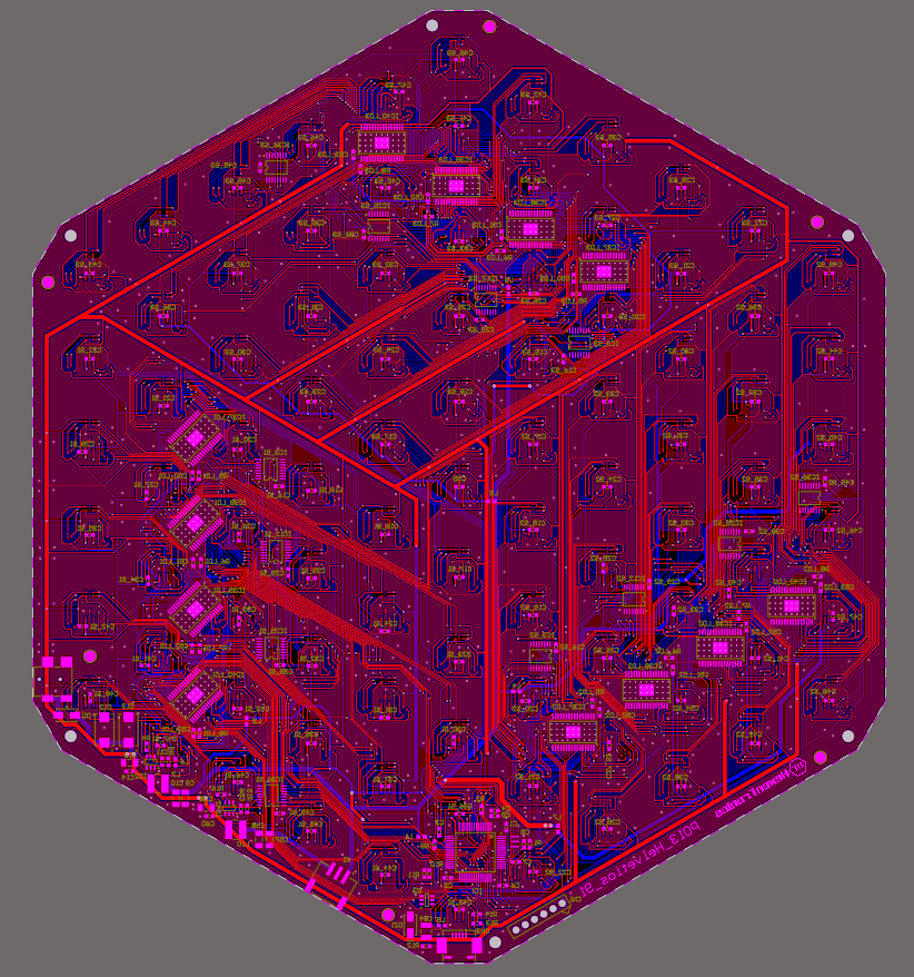
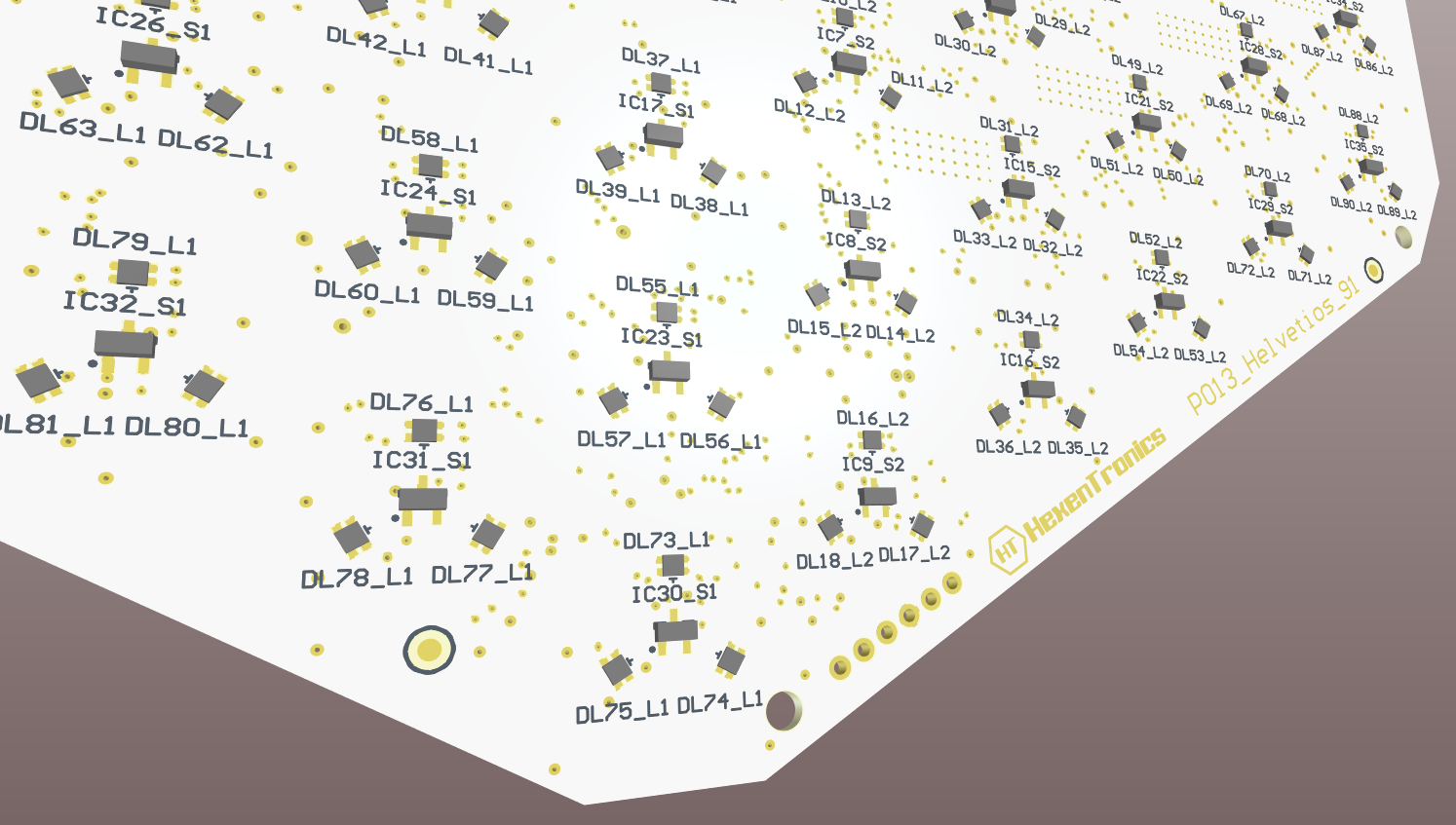
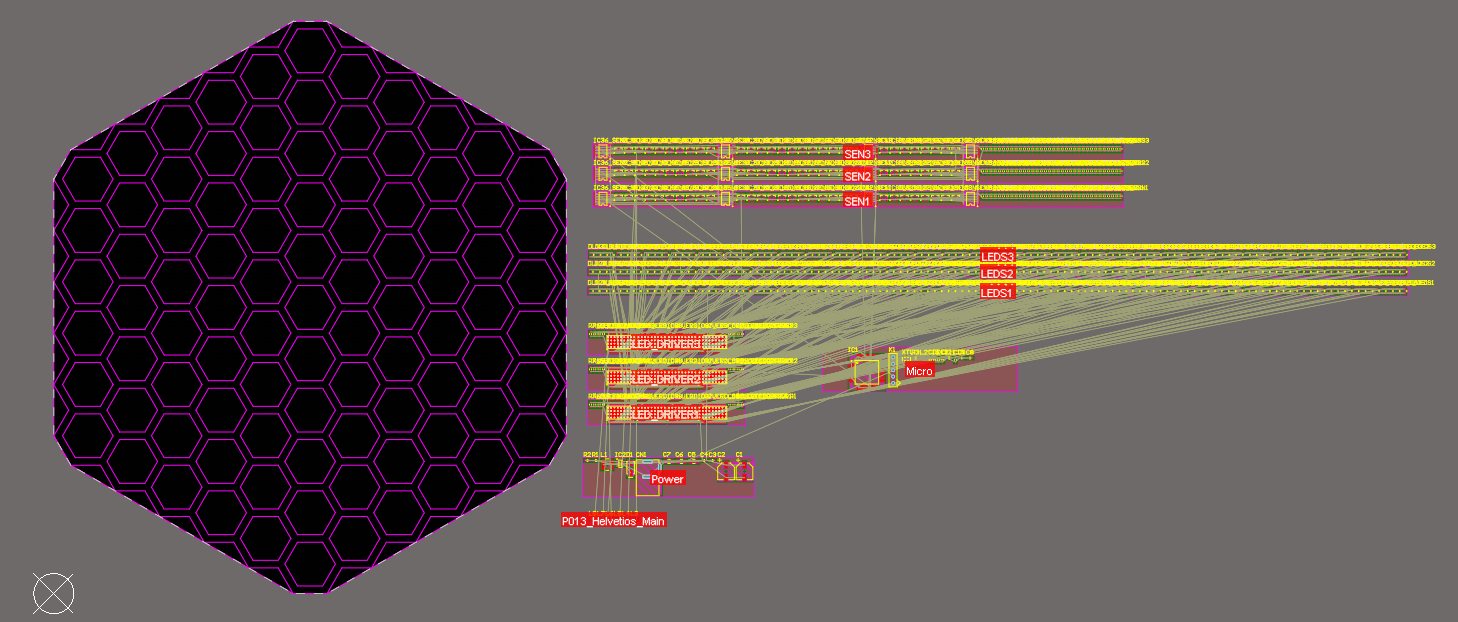
Schematics finished, time to place a looot of leds
03/11/2021 at 19:00 • 0 commentsWell, I've finished the schematic so I've started to place the components. It will take a while due there are 559 components in total, with 273 LEDs.
And this is the A4 prototype with only 91 cells, I have drawings of other bigger designs with 169 cells and even 505 in a 70x70cm board!
This is made in only one circuit due the small size of the boardgame, for bigger boards I'll use smaller circuits as 'rows' and connect them, so it will be easier to design.![]()
![]()
-
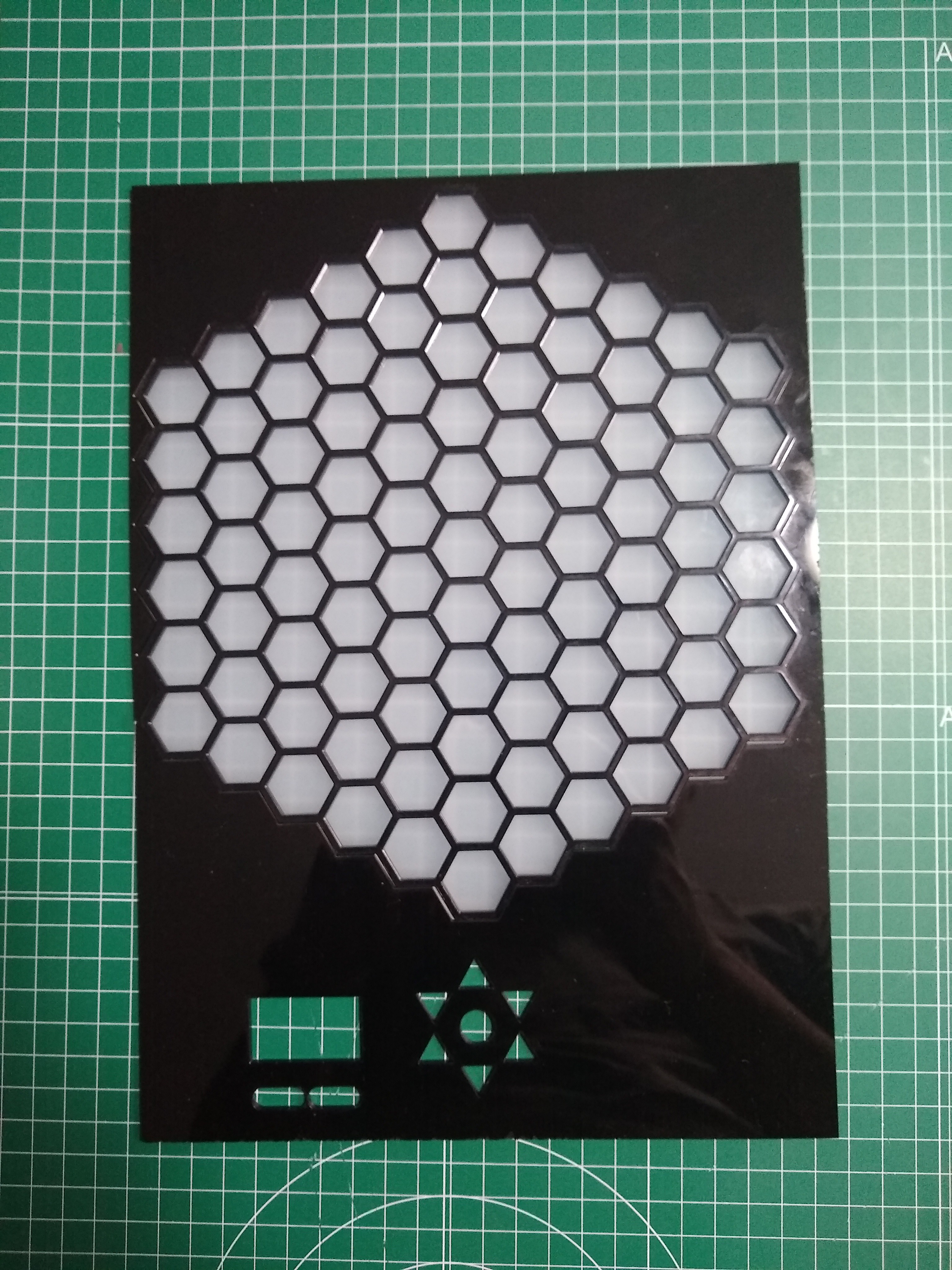
Laser cutting a 91 cells board.
01/19/2021 at 19:37 • 0 commentsI've made a laser cut prototype of the board. It's the led diffuser an the top face of the board. I will start to a 91 cells board, due it fits well in a A4 sheet and I could make a single PCB with all the electronics. This will help to develop the software, later it could be escalated to bigger boards with more cells and grouping cells to simpler pcbs interconnected.
This design will be a single board with all the sensors and leds. The microcontroller will have an usb connector to manage it from the raspberry or other system.
I've cut also what will be the interface to the board, a little oled screen and some buttons to select and navigate the boardgame cells. This interface will be connected directly to the Raspberry Zero
![]()
Also I've been busy making the schematics, now It's time to component placing and start to route the pcb.![]()
I will add later the schematics when are finished.
Interactive Cell Board game
An electronic board game with magnetic piece detection and illuminated cells.