-
13.3v, 5v and 12v Output Options
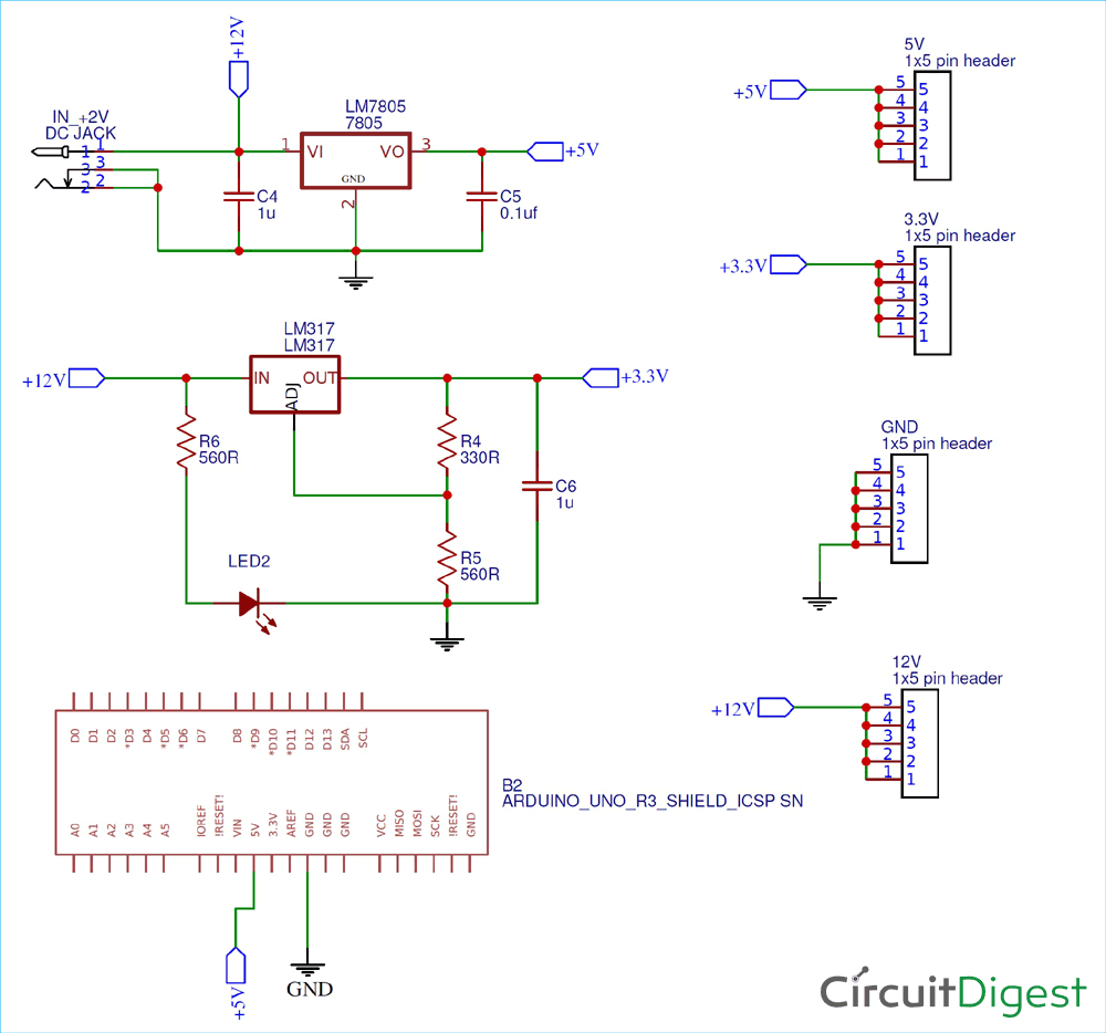
Circuit Diagram
The circuit diagram and schematic for Arduino Power Supply Shield is pretty simple and doesn’t contain much component placement. We will be using 12V DC Barrel Jack for main voltage input for the whole Arduino UNO Shield. The LM7805 will convert 12V to 5V output, similarly the LM317 will convert 12V to 3.3V output. LM317 is popular Voltage regulator IC can be used to build variable voltage regulator circuit.
![]()
To convert the 12V to 3.3V we are using 330Ω and 560Ω as voltage divider circuit. It is important to place an output capacitor between the output of LM7805 and Ground. Similarly between the LM317 and Ground. Keep in mind that all grounds should be common and the required track width should be chosen depending upon the current flowing through the circuit.
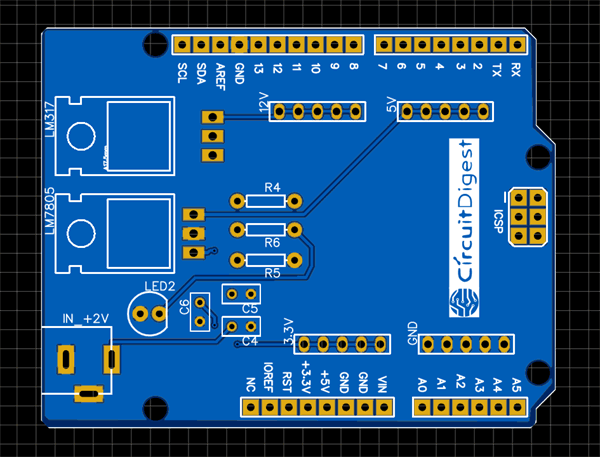
Fabricating the PCB for Arduino Power Supply Shield
After making the circuit ready, it’s the time to go ahead with designing our PCB using the PCB design software. As stated earlier we are using EasyEDA PCB Designer, so we just need to convert the schematic to a PCB Board. When you convert the schematic into board, you also need to place the components in the places according to the design. After converting the schematic above to board my PCB looked like below.
![Fabricating the PCB for Arduino Power Supply Shield]() Assembling the PCB
Assembling the PCBAfter the board was ordered, it reached me after some days though courier in a neatly labelled well-packed box and like always the quality of the PCB was awesome.
![Assembling Arduino Power Supply Shield PCB]()
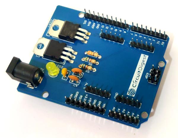
Get the soldering kit and start placing all the components in the right pads of the PCB Board. The soldering is easy to finish as there is not much components used in this project.
When the soldering is finished your board should look like below.
![Soldered Arduino Power Supply Shield PCB]()
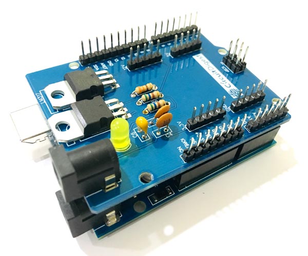
In this Power Shield the burg pins used is of male to male 20 mm connectors. You can use Male to Female Burg pins depending upon the availability. The 20mm burg pins are suitable for Arduino Shield and fits well for on Arduino UNO.
![Circuit Hardware for Arduino Power Supply Shield]()
Testing the Power Supply Arduino Shield
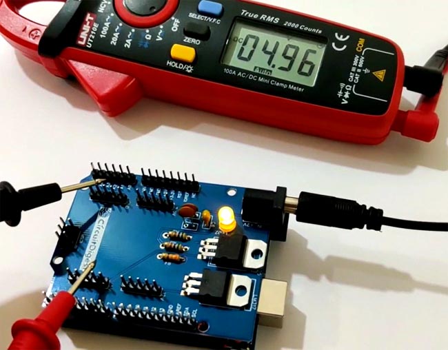
It is really easy to test the Arduino shield. Just place the shield on to the Arduino UNO and give it a 12V supply from the input barrel jack. The shield can take input voltage of maximum up to 34V without damaging the components.
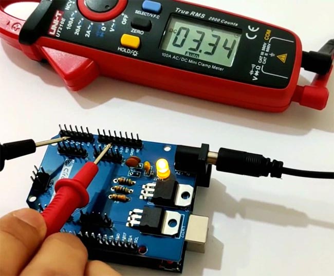
You can check all the output voltage i.e. 3.3V, 5V and 12V using a digital multimeter. If all went good including designing and soldering of the components then you will be able to note down the exact output voltage at the output pins.
![Testing 3.3v Power Supply Arduino Shield]()
![Testing 5v Power Supply Arduino Shield]()
DIY Arduino Power Supply Shield with 3.3v, 5v and
The power supply is one of the most important part of whole project and there is always need of multiple output voltage power supply.
 Assembling the PCB
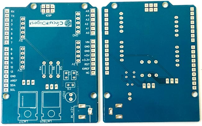
Discussions
Become a Hackaday.io Member
Create an account to leave a comment. Already have an account? Log In.