-
1Step 1: Cutting the Shape
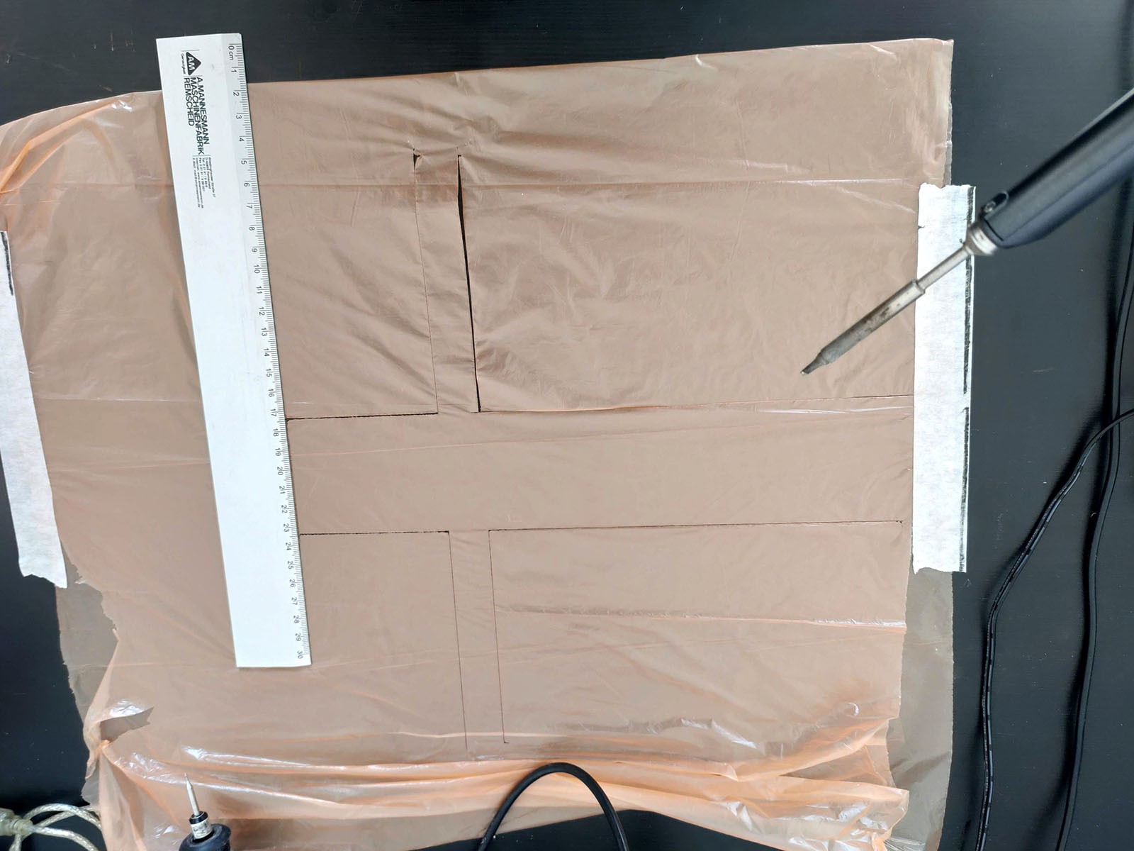
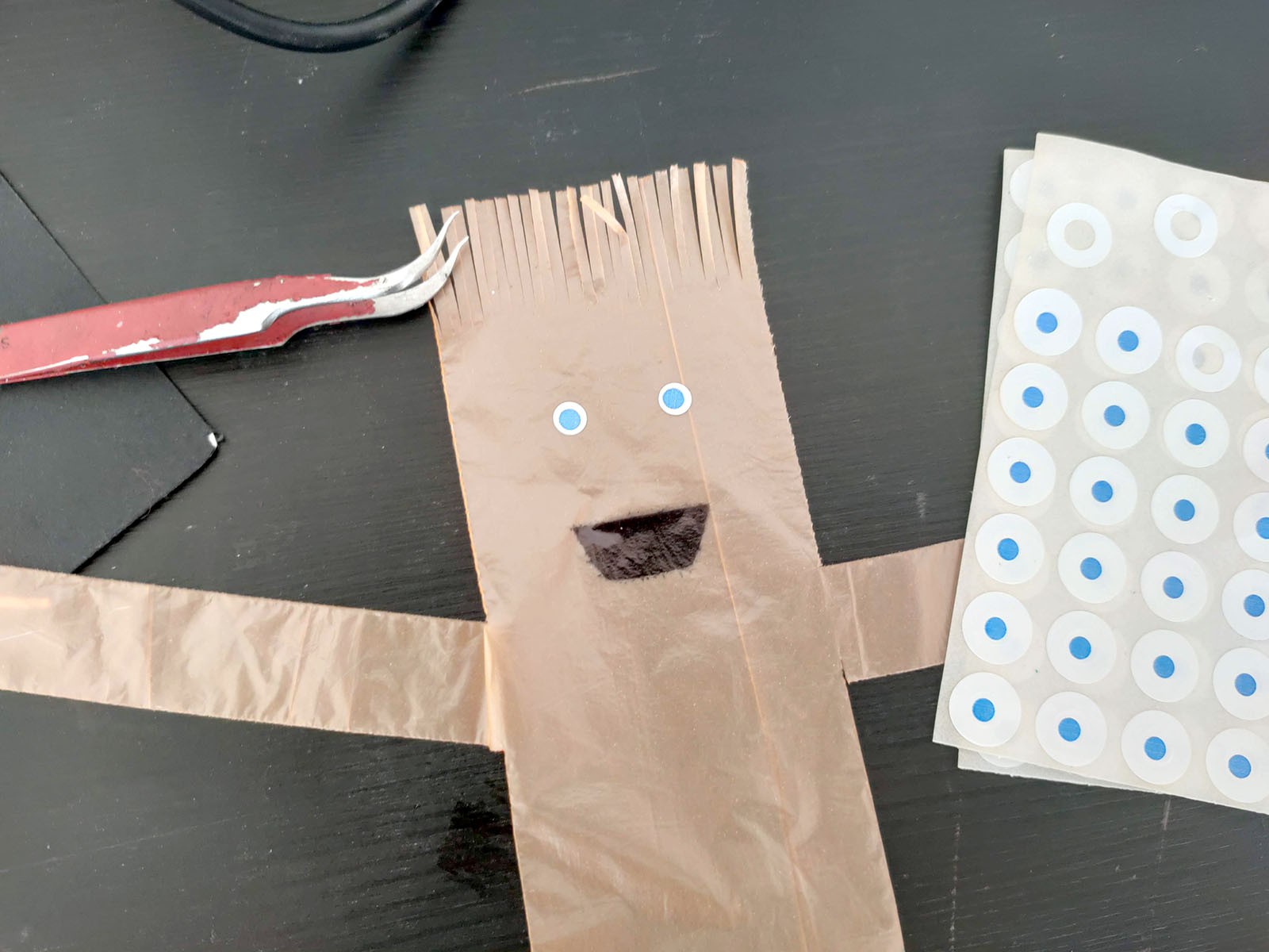
To easily create the Tube Man, I found out the best way for me is to superimpose two layers of colored trash bag, set the soldering iron to 180 Degrees (Celsius), and cut the shape with quick passes, in order to not burn the plastc bag.
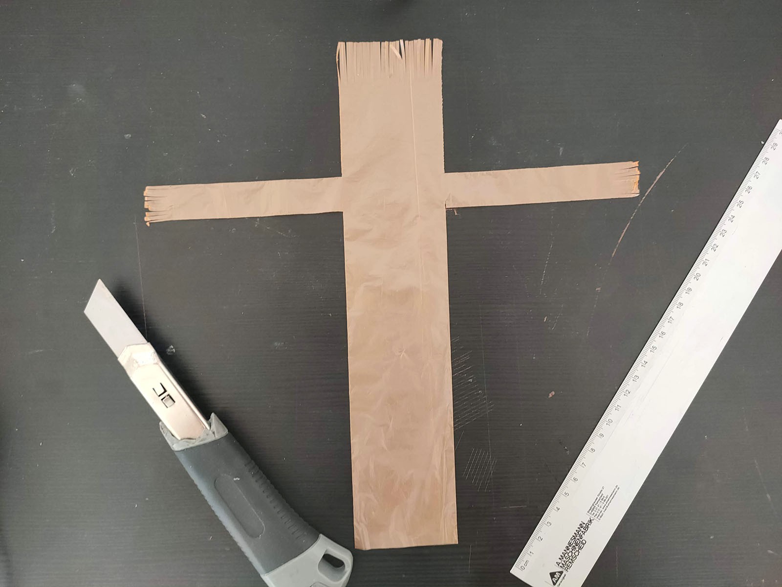
After some practice, you will be able to cut And weld together the borders quite quickly. I cut freehand, the size is about 26cm tall, arms are 12cm long, 2cm high, body is 6cm large, head is about 8cm long.
The bottom of the body must be cut with a cutter, not with the soldering iron, because the two plastic bag layers must not weld here, we need air to pass through.
At the end, I use the cutter to create the fringes on top of the head and at the hands, to let air go out here.
![]()
![]()
-
2Step 2: Details on the Body
![]()
![]()
![]()
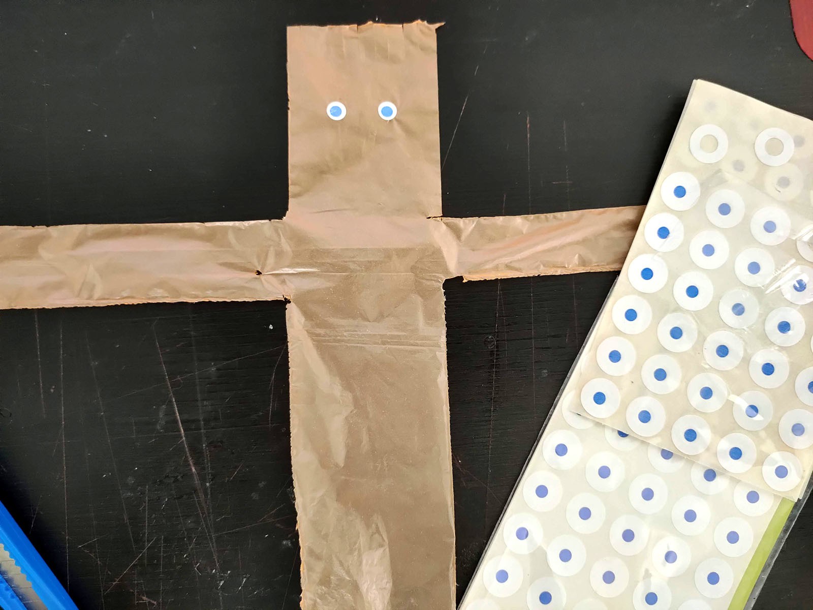
To add the eyes, I found these blisters of adhesive hole reinforcements, that have a blue center with some white on the border, already cut. I discard the adhesive hole reinforcements, and keep the center parts to quickly create eyes!
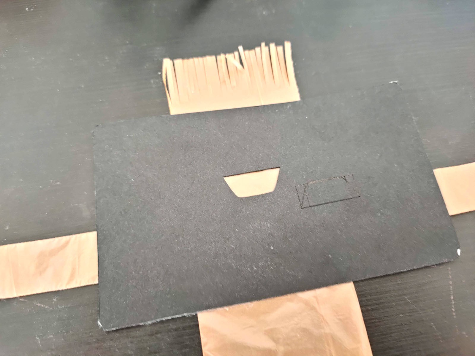
For the mouth, I cut with laser cutter (but you can do it by hand too) the template on cardboard, then with a marker you can easily draw it.
-
3Step 3: Create the Base
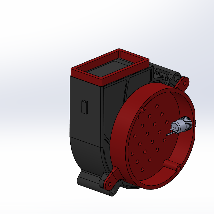
I designed the parts to be 3D Printed with CAD (Solidworks) and you can download them here.
Parts were 3d printed with a Zortrax M200, but any filament-based machine will work.
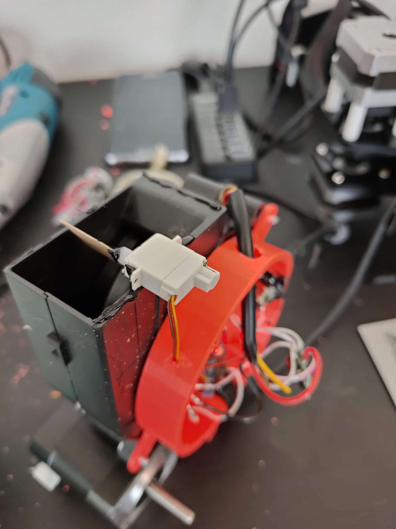
To assemble the parts, hot glue is used.
A round metallic mesh was cut about 80mm in diameter.
On the bottom of the centrifugal fan, four soft plastic feets keep it in place when powered on.
A servo motor is optional, but can move the air flow and make the Tube Man movements more various.
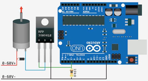
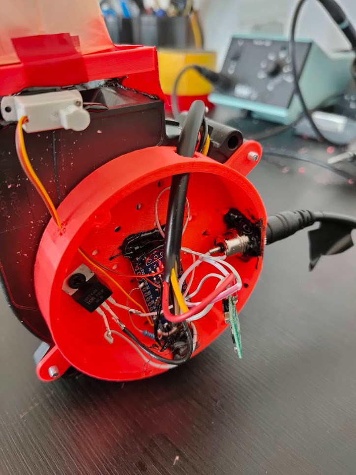
The electronics is based on an Arduino and an IRFZ44 transistor.
You cna use a DC jack and simply connect a DC power supply to the fan. But with an Arduino, you have control on the air flow, making it stronger, more gentle, alternating it, so I suggest this way.
The servo motor is connected on pin 9 and kept "sweeping". The Arduino code is also here, ready to be progrmmed in an Arduino Nano, or similar.
![]()
![]()
-
4Step 4: More on Electronics and Circuit
![]()
![]()
The connection scheme is shown in the picture. The servo connection is optional, in case you use it, yellow wire goes on pin 9, red on +5V, brown on Gnd.
Since the power input from the DC power supply is too much to power the arduino nano, a step down converter like the Pololu 5V, 500mA Step-Down Voltage Regulator D24V5F5 is used.
DIY miniature Wacky Waving Inflatable Tube Guy
Wacky Waving Inflatable Tube Guy!!! Wacky Waving Inflatable Tube Guy!!!
 Madaeon
Discussions
Become a Hackaday.io Member
Create an account to leave a comment. Already have an account? Log In.