 oneohm
-
Functional Block Diagram
09/21/2020 at 23:42 • 0 comments![]()
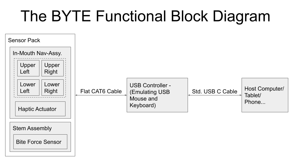
Here is the basic architecture of the current prototype. Additional interface options are in the works, including WiFi & Bluetooth connectivity and discrete outputs for replacing existing buttons, switches or other controls.
-
The Logic of Tongue Control
09/13/2020 at 22:43 • 0 commentsCerebral palsy, spinal cord injuries, stroke, and other neuromuscular disorders may lead to tetraplegia, a condition that results in loss of sensory and motor functions of all four limbs and the torso.
Many approaches are used to help leverage the remaining functional parts of the body for computer interfacing including:
- head tracking
- eye gaze tracking
- speech recognition
- mouth/chin-operated mouse/joysticks
- sip-n-puff
- brain-controlled interfaces
- tongue-operated interfaces
Some limitations of existing approaches:
Eye trackers use eye movements to control the mouse cursor on the computer screen. Unfortunately, they interfere with visual functions because the computers have difficulty determining whether an eye movement was a control input or looking at an object, they require a camera mounted in front of the user, which can block the field of view, and they are susceptible to lighting conditions and need frequent adjustment if the user’s head position is changing.
Voice recognition systems are efficient for typing but are slow and not intuitive for controlling a computer mouse or a powered wheelchair. They are also susceptible to ambient noise, and therefore, not suitable for outdoor environment.
Head trackers and mouth/chin joysticks require head and neck movements, which do not cover tetraplegics who have limited or no head control, or they cause fatigue in weakened cervical/shoulder muscles, and cannot be used over extended periods.
Sip-and-puff (SnP) is one of the most popular ATs for driving powered wheelchairs due to its low cost and ease of use, but offers only four commands. It is to slow for computer access and offers limited options. Moreover, the SnP straw and tubing require frequent cleaning or replacement.
EEG-based BCIs are too slow because of the limited EEG bandwidth, and susceptible to motion artifacts and interference. They also have a cumbersome setup procedure and need headcap/gel for good electric contact to the scalp.
The Neuralink has some promise, although not everyone will be willing to have a sizable hole drilled into their skull...Advantages of tongue-operated interfaces:
Since the tongue is connected to the brain by the well-protected hypoglossal cranial nerve, it generally retains functionality in those with tetraplegia.
The tongue has many inherent capabilities that make it an excellent control modality for those with tetraplegia. The area of the motor cortex dedicated to the tongue and mouth rivals that of the fingers and hand, providing the tongue with sophisticated motor control and manipulation capability.
Tongue movements are natural, intuitive, and do not need thinking or concentration. Hence, assistive devices that operate based on tongue motion are easy to learn and use. Additionally, the tongue can move both quickly and accurately and since the tongue muscle is similar to the heart muscle it does not fatigue easily.
Moreover, its position inside the mouth gives the users of tongue-operated devices a certain degree of privacy.
The dexterous, intuitive, rapid, precise, and tireless motion of the tongue is the ideal interface for those with limited mobility to access computers/smartphones, drive wheelchairs, and interact with their environments.
Summarized from this paper on tongue Interfaces out of Georgia Tech:
Tapping into tongue motion to substitute or augment upper limbs -
Prototype and production cost estimates
09/11/2020 at 05:53 • 0 commentsI believe that an initial production batch for early adopters should be possible for around $150 - $200 each. This would help to cover the injection mold tooling and manufacturing equipment costs. Later batches could be offered at a lower price, hopefully dropping below $100.
Initial estimates for pricing at different quantities:
~ 100 units ~ 500 units ~ 1000 units $150-200 $120-150 < $100
Throughout development of this project, my objective has been to create something innovative that will improve the quality of life for people. But in order to realistically make my project available to any who will benefit, I must also prioritize affordability.
Rather than working to add features and complexity, I have put a lot of effort into simplifying the design, being careful to preserve core functionality. A reduced part count not only lowers cost but, more importantly, increases reliability.
The cost for the individual parts of my prototypes includes quite a bit of overhead: shipping charges, larger-than-required minimum order sizes, and non cost optimized part selection.
For additional pricing details the costed BOM is available on Github: Prototype BOM
Material costs for production quantities (on the order of 1000 units) will be much lower, but there are also additional considerations that need to be taken into account when transitioning to production. Assembly, testing, packaging, shipping, and support costs are often overlooked or underestimated when bringing a new product to market.
While I would love to be in a position to make the final product available for free to all, it is important to be realistic. In order to introduce a quality product to the market, back it up with responsive support, and still be able to invest in ongoing development/improvements, the sale price must be at least somewhat higher than the raw manufacturing cost. That said, I hope anyone who desires to make their own BYTE at home would be able to follow my published instructions.
-
Currently Available Solutions
09/10/2020 at 03:12 • 0 commentsAs far as I can tell, there are no commercially available tongue operated controllers currently on the market. This seems to be an important unmet need.
The most common competitive devices are mouth controlled joysticks. There are several models commercially available. I was very surprised that they all seem to be extremely expensive; especially when considering that many of their users have limited budgets.
Two common models are the QuadJoy and the Jouse, both ringing in at well over a thousand dollars. The TetraMouse and QuadStick are less expensive, but still cost many hundreds of dollars each.
While mouth controlled joysticks are in some ways similar to the BYTE, there are important differences. One differentiator is the type of muscles involved in using these devices.
The lip, jaw and neck muscles involved in operating these joysticks tire much more quickly than the tongue (Think of the last time you had to hold a smile just a little too long for a slow photographer...). The tongue is very similar to the type of muscle comprising the heart, rendering it nearly tireless.
Another advantage of a tongue controlled interface device has to do with the robust and direct connection of nerves from the tongue to the brainstem. Most people with spinal cord injuries, and many with otherwise paralyzing neurological diseases, can still move the tongue.
Several tongue operated controllers have been demonstrated, although mostly limited to one-off prototypes and academic research. A well known example comes out of Georgia Tech's Bionics Lab, the Tongue Drive System, using a magnetic tracking approach. It requires the user to have their tongue pierced with a magnetic stud; for those with a strong stomach a paper detailing the procedure is available here.
Aside from no piercing requirement, the BYTE has a major advantage over a magnetic tracking approach, especially for those with cerebral palsy - since it is pressure controlled, there is no need to accurately position the tongue within the mouth or to make small precise movements.
-
Advantages of Force Control
09/09/2020 at 23:27 • 0 commentsInstead of responding to tongue position, the BYTE is force controlled. This is an important distinction as some people with cerebral palsy find it challenging to perform fine and precise articulation of their tongues.
With the BYTE, the whole tongue can be pressed against the nav-button and rocked or tilted in the desired direction. There is no need to hold the tongue in a specific position or to make small precise movements; in fact, the exact position of the tongue is largely unimportant.
For users who may suffer from spasms of their tongue or chin muscles, additional averaging and filtering can be implemented in the controller. This approach will still provide accurate pointing since following a spasm the tongue need not return exactly to its previous position, but simply re-apply pressure in the desired direction.
-
Controller Details
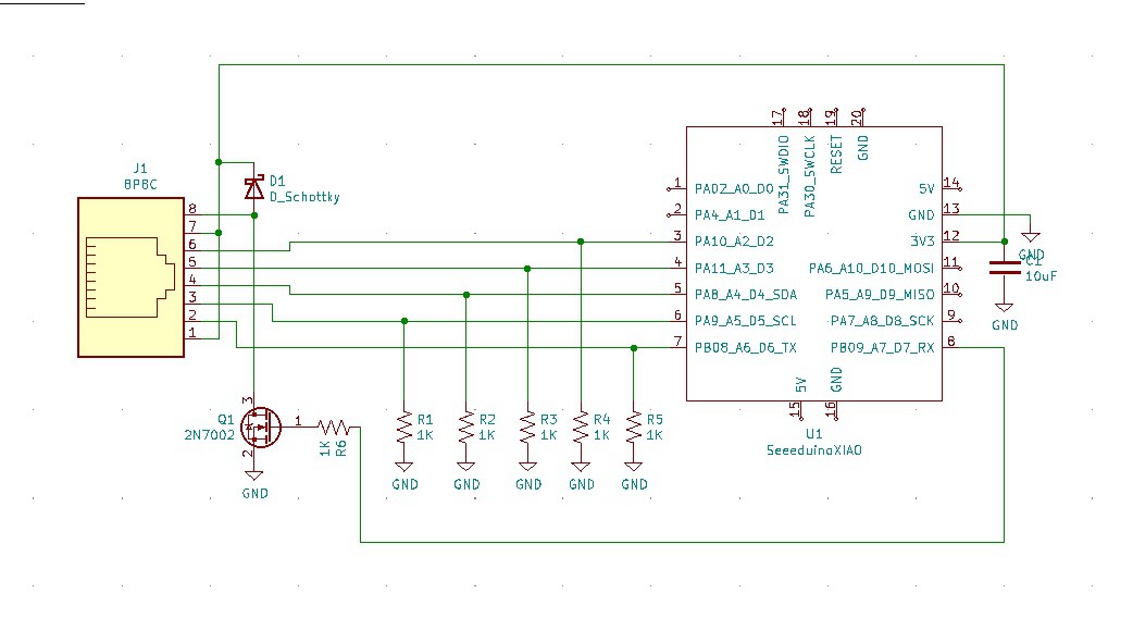
08/31/2020 at 04:53 • 0 commentsThe controller acts as a bridge between the sensor module and the host system. A set of resistor dividers measure the five force sensitive resistors while a transistor drives the haptic actuator.
![]()
![]()
I am using a SAMD21 based micro-controller module (the SeeedStudio XIAO). It incorporates an oscillator, voltage regulator, USB connector, EMI shield and more for less than $5. In production these components will be directly incorporated into the control board design, but while prototyping it would be difficult to beat the cost.
-
Assembly Process
08/30/2020 at 22:18 • 0 commentsPutting the sensor together:
-
Prototyping -> Manufacturing
08/27/2020 at 21:50 • 0 commentsThis Log entry addresses the readiness for manufacturing and the path from prototyping to production for each component of the BYTE.
Many of the parts for prototyping have been produced either with a 3D printer or a fiber laser engraver. These tools are excellent for rapid design iteration, but are not ideal for production quantities.
Purchased Parts:
The silicone enclosure, M2 screw, o-ring, and flat CAT6 cable are commercially available purchased parts.Plastic:
Plastic parts are 3D printed for the prototypes, but would transition to injection molding for production. They have been designed in a way to simplify the injection molding tooling and thus minimize the cost. Currently the stem portion is printed as three pieces, but when molded, can be combined into a single part.Since the plastic parts are approximately the same size and volume, they can likely be molded simultaneously in a family tool, further reducing cost.
Silicone Disc:
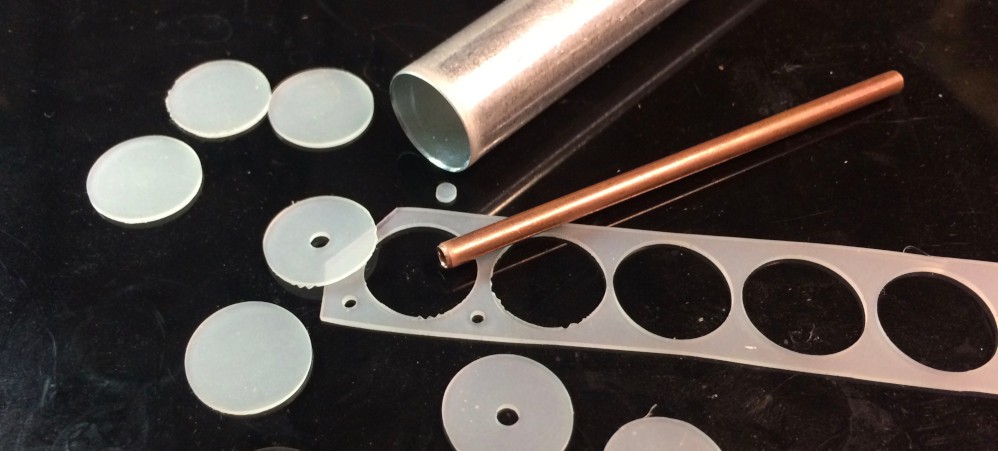
Using sharpened pieces of tubing, I am punching this part from 0.032" silicone rubber sheet for the prototypes. This process is really tedious, but fortunately these parts can be rapidly made a whole sheet at a time with a steel-rule die and a press. There are also many companies that specialize in producing this type of part.![]()
Common Contact:
I am currently laser cutting this part from 0.1mm copper sheet; this process is quick and easy and scalable up to small scale production quantities. Larger scale production would be better suited to photo-chemical etching, where large sheets containing hundreds of parts can efficiently be produced.![]()
Force Sensitive Resistor Disc:
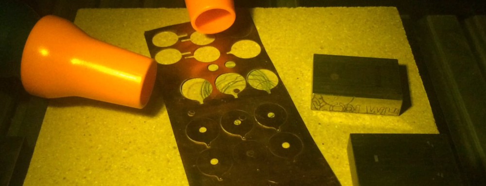
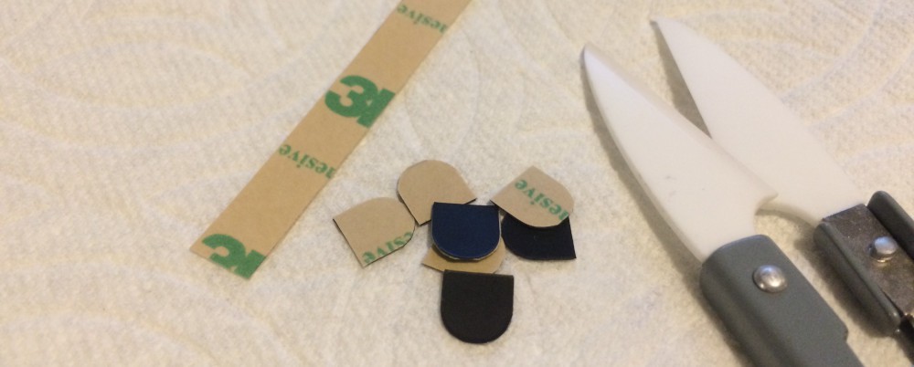
These are individually laser cut from 3M 1706 conductive sheeting. Larger quantities would be die cut with a steel rule die, possibly with the same tooling (or even at the same time) as the silicone disc.![]()
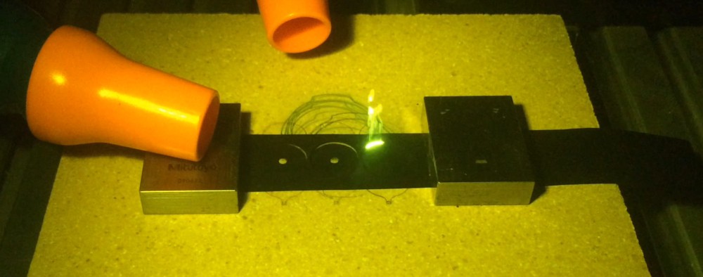
Stem Force Sensitive Resistor:
This part is produced from the same 3M conductive sheet backed with 3M 468MP adhesive transfer tape. This is currently done by laser cutting the conductive sheet, then applying them to the transfer tape and manually cutting the profile. This is done because the laser is able to cut the conductive sheet due to its dark color and high carbon content, while the transfer tape is basically invisible at the wavelength of my fiber laser, rendering it uncuttable.![]()
Production quantities would be produced by laminating the conductive sheet to the transfer tape, then using a steel rule die to kiss-cut the parts. This leaves the transfer tape backing intact, but cleanly cuts through the conductive and adhesive layers, leaving an easily manageable sheet of stickers ready to apply.
PCBs:
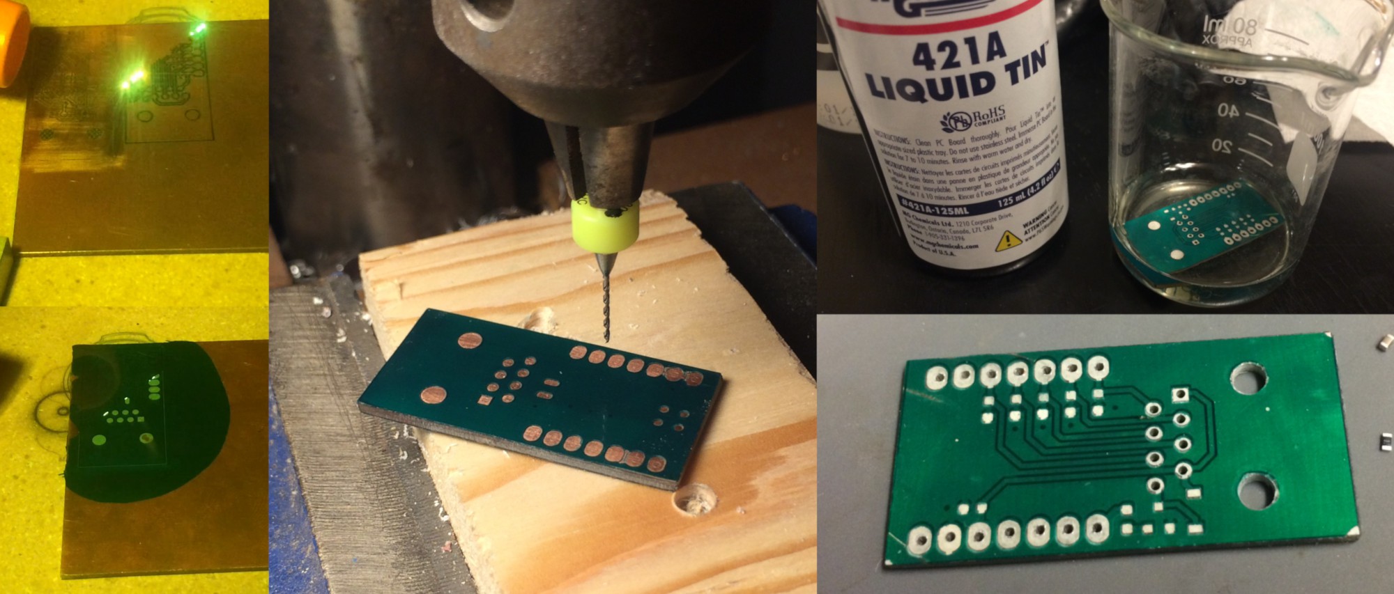
My prototype process for PCBs is to first isolate the tracks by laser ablating the copper. UV curing soldermask resin is then applied over the whole thing and--once cured--the laser is used again to selectively remove the soldermask exposing the required pads. After cleaning up the residue with Isopropyl alcohol, I hand drill the holes on a drill press. Next they are dipped into MG Chemicals 421A Liquid Tin to improve solderability and prevent oxidation. Finally I cut the board outline on a mini tablesaw, and finalize the shape with a bench grinder.![]()
The convenience of quickly producing my own circuit boards is great for prototyping, but for larger quantities a traditional PCB fabricator is the way to go. In the last few years the cost and lead-time for commercially produced PCBs has become very reasonable.
For these small boards, it makes the most sense to create an array of arrays. The three boards required for each BYTE (Nav, Bite, and Control boards) will be arranged into a rectangular board, which will in turn be tiled into a more manageable size with perhaps 10 or 20 complete sets per panel.
-
Design Process - Evolution!
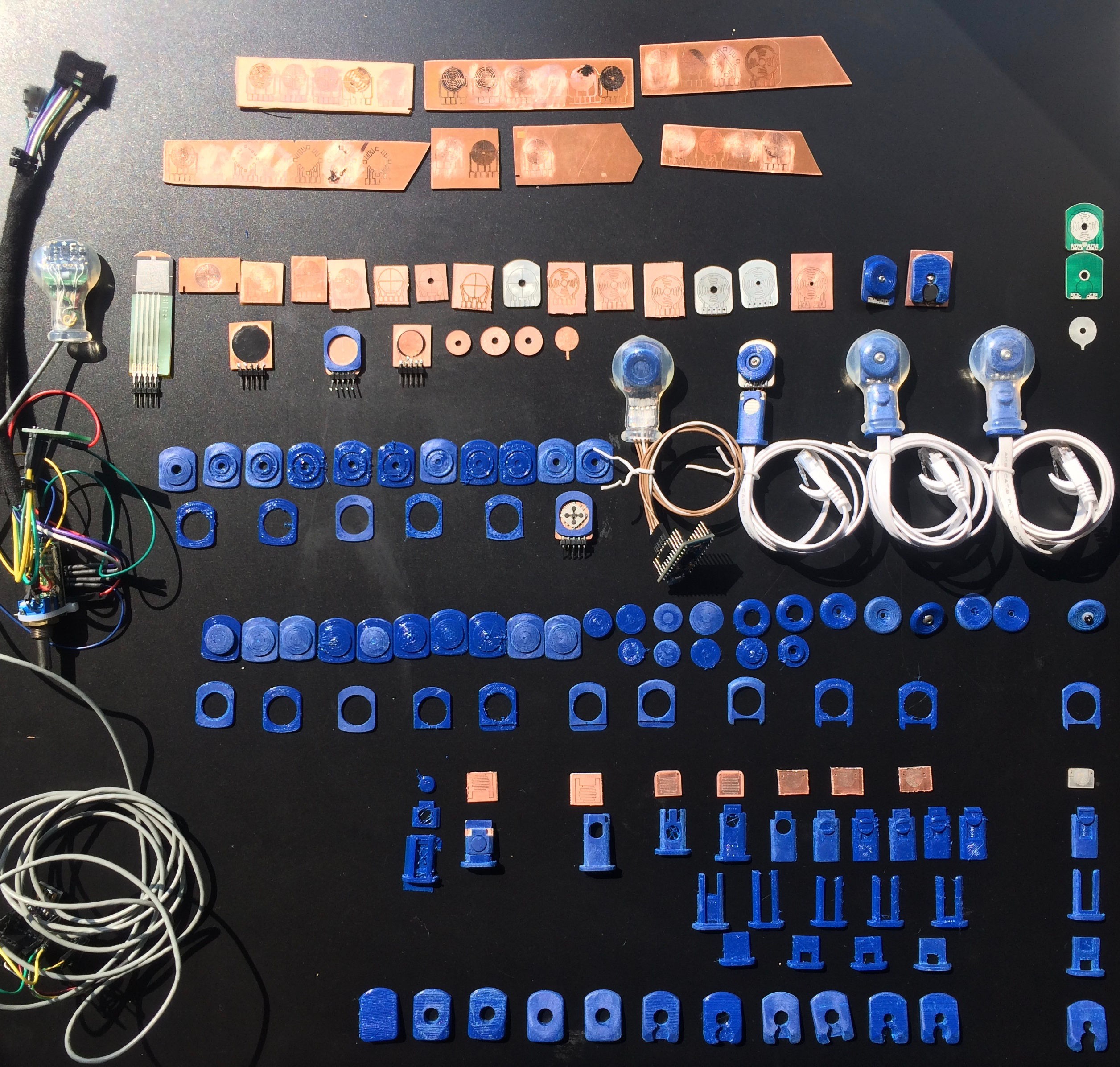
08/26/2020 at 22:40 • 0 commentsRather than attempt to describe each step of the design process and the decision tree that has led to the design today, I dug through the pile of old parts and selected a few to create visual demonstration in the form of a timeline.
![]()
Many look nearly identical, but each one represents a minor design change.
In the upper left you will find the original alpha prototype that started it all (now stripped of its enclosure for the sake of progress). From left to right you can see the rough chronological evolution of each part.
Towards the center you can track the progression of an ill fated feature. A five button navigation switch originally resided on the back of the sensor board, but sadly went extinct when the central screw was introduced. Fortunately its intended functionality was able to be preserved with some firmware changes.
In the far right column are the latest parts, ready to be assembled into the next complete prototype.
Along the top is some trial and error testing (mostly error...) for directly laser etching the PCBs. It is tricky business to cleanly remove copper and leave the underlying fiberglass unharmed, but worth it in the end as this was the key to rapidly improving the design.
Directly laser etching the PCBs removes days or weeks of lead time between each revision - These small boards can be etched and ready to test in less than two minutes!
-
Navigation Sensor Stackup
08/26/2020 at 18:48 • 0 commentsThe navigation sensor stack-up is designed to be extremely durable while also being capable of detecting delicate pressure and delivering precision direction control.
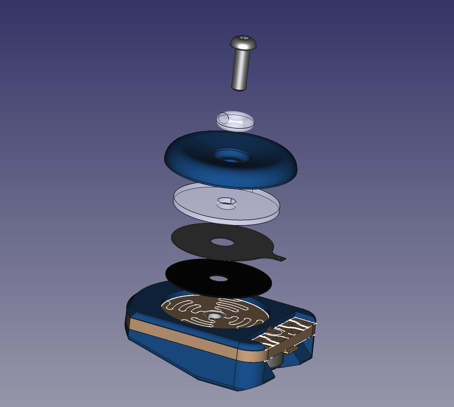
Here is an exploded view of the navigation sensor:
![]() From the top down we have:
From the top down we have:- M2 screw - Maintains alignment and provides preload force
- Silicone O-Ring - Distributes preload force to the Nav-Button
- Nav-Button - The raised rim transmits the user's applied pressure downward
- Silicone Disc - Spreads out pressure to improve directional sensitivity
- Common Contact - Thin copper contact shared by the four sensor zones
- Force Sensitive Polymer Disc - Carbon-impregnated polyolefin (3M 1706)
- PCB - Interdigitated pattern with four symmetric sensor zones
The result is an array of thru-mode force sensitive resistors. Pressing on the Nav-Button compresses the conductive polymer decreasing the resistance between the common contact and the zone(s) below the area where the pressure is applied.
This approach has some important advantages over the more commonly used shunt-mode construction.
Thru mode force sensitive resistors respond faster and behave more linearly during the force loading phase. They can also be force preloaded, which reduces the minimum force required for contact detection and improves the output linearity.

 From the top down we have: