-
1Introduction
Hey, what's up, Guys! Akarsh here from CETech.
This project of mine is going to help your life become easy and you are going to feel like a king after controlling appliances in your house by just giving a command to Alexa.
The main thing behind this project is nothing but the functioning of two modules ESP8266 and Relay Module. Basically we are going to control our ESP8266 using Alexa.
Towards the end of the article, we will be doing simple connections between the ESP8266 and relay module followed by the code for connecting and controlling ESP8266 with Alexa.
Let's start with the fun now.
-
2Get PCBs for Your Project Manufactured
You must check out PCBGOGO for ordering PCBs online for cheap!
You get 10 good quality PCBs manufactured and shipped to your doorstep for 5$ and some shipping. You will also get a discount on shipping on your first order.
PCBGOGO has the capability of PCB assembly and stencil manufacture as well as keeping good quality standards.
Do check them out if you need to get PCBs manufactured or assembled.
-
3Looking at the Relay Module
The Relay Module is a convenient board which can be used to control high voltage, high current loads such as lamps and AC load. It is designed to interface with a microcontroller such as Arduino, ESP8266 and etc. It comes with a LED to indicate the status of the relay. The relay modules generally have the following terminals:
1. NC(Normally closed)=The normally closed configuration is used when you want the relay to be closed by default, meaning the current is flowing unless you send a signal from the Arduino to the relay module to open the circuit and stop the current
2. NO(Normally Open)=The normally open configuration works the other way around: the relay is always open, so the circuit is broken unless you send a signal from the Arduino to close the circuit.
3. Common pin=It is generally in the middle
4 Input pins=It is the pin through which relay is connected to the controlling device.
If not mentioned on the module we can find out the NC pin using a multimeter in continuity setting by connecting the common with the other terminal through multimeter probes if it creates a beep sound then the pin is NC.
-
4Connecting ESP8266 With Relay Board
The modules can be purchased from here(Link to be added). You will definitely get some good deal here.
Connections are in two parts:
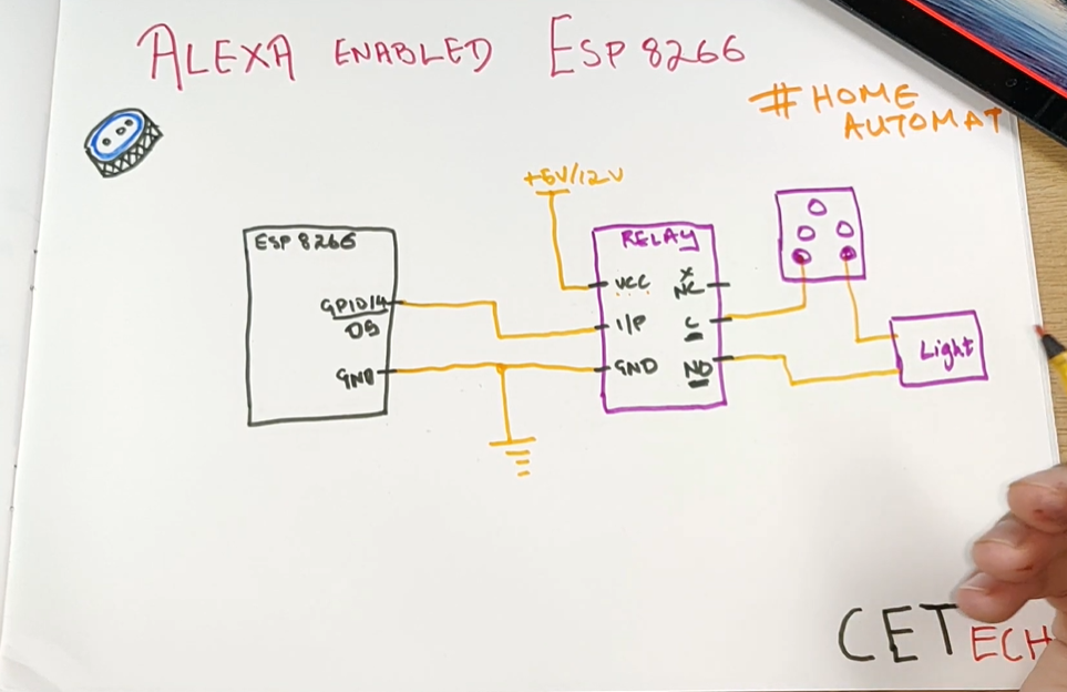
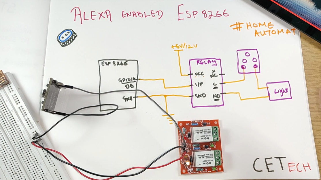
Between ESP8266 and Relay Module:
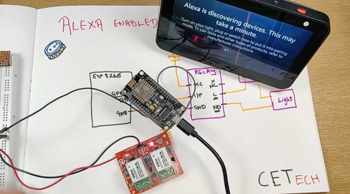
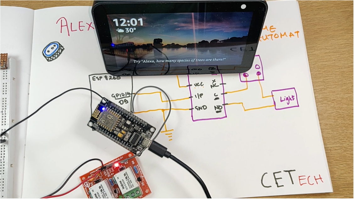
1. Connect D5 (GPIO14) pin with the input of the relay. You can connect more relay inputs as well by connecting them to other GPIO pins available.
2. Connect Vcc of the relay module to 5V/12V power supply based on your relay module.
3. Connect GND of ESP8266 with GND of relay module and then connect them to GND of power supply.
Between the Relay module and Appliance:
1. Make sure power Socket is turned off before connections.
2. Connect the common with one terminal of the socket.
3. Connect the other terminal of the socket to a terminal of the appliance.
4. Connect the other terminal of the appliance to the NO terminal of the relay.
Once this step is complete you can move over to the software part.
-
5Download and Setup the Arduino IDE
Download the Arduino IDE from here
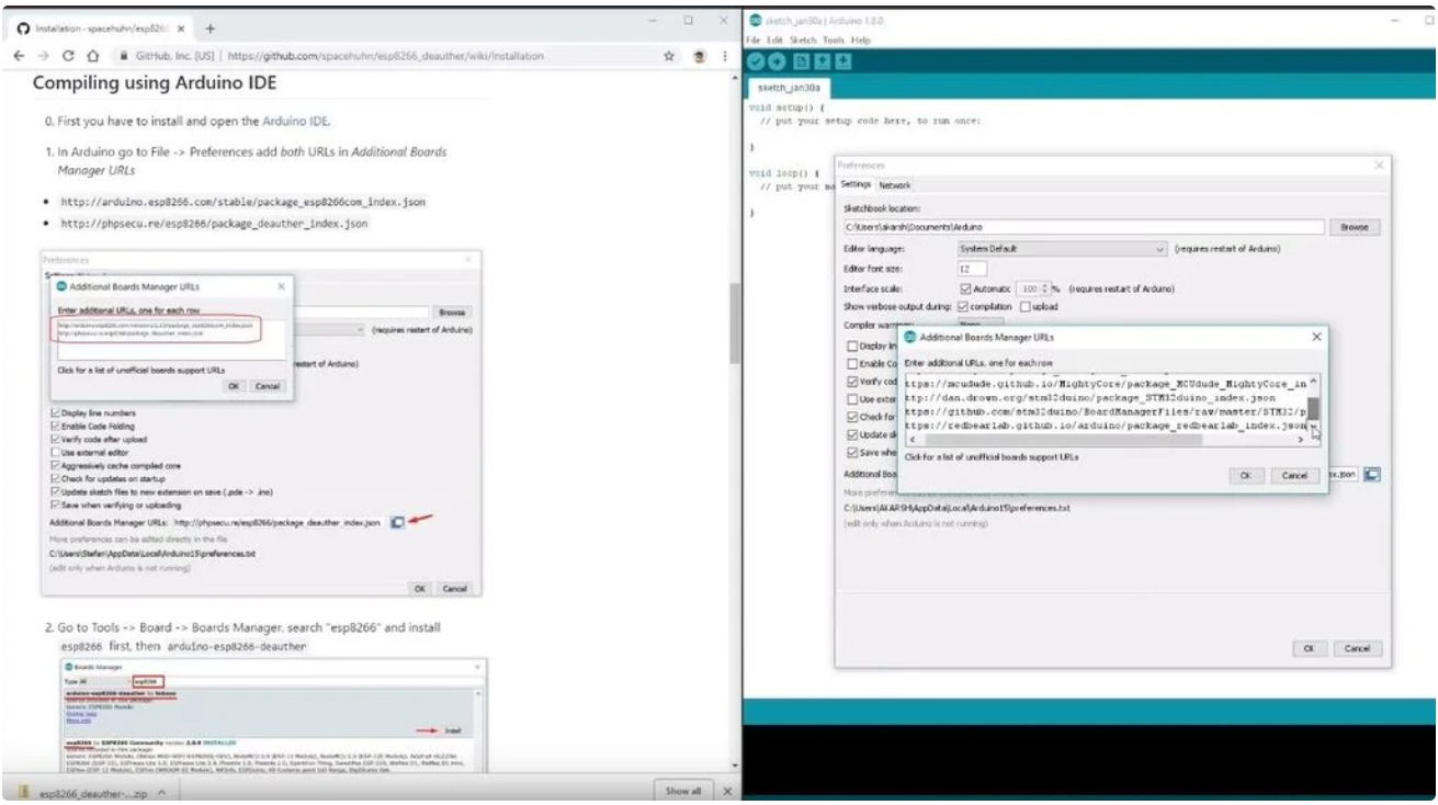
1. Install the Arduino IDE and open it.
2. Go to File > Preferences
3. Add http://arduino.esp8266.com/stable/package_esp8266... to the Additional Boards Manager URLs.
4. Go to Tools > Board > Boards Manager
5. Search for esp8266 and then install the board.
6. Restart the IDE.
-
6Adding Additional Libraries to Arduino IDE
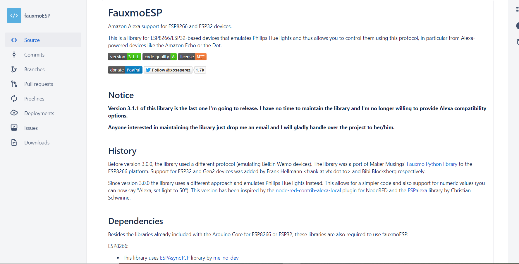
We will be using fauxmoESP library to control our ESP8266 using Alexa.
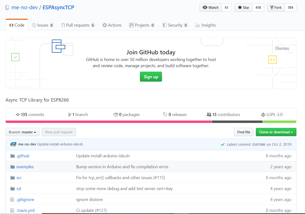
This library requires another library to function which is ESPAsyncTCP.
Learn about the fauxmoESP library from here. For ESPAsyncTCP head over to this page.
FauxmoESP library can be downloaded from here.
ESPAsyncTCP library can be downloaded from here.
After downloading these libraries we need to extract them and put them in the libraries folder of the Arduino IDE which can be found under the documents folder.
-
7Coding the Module
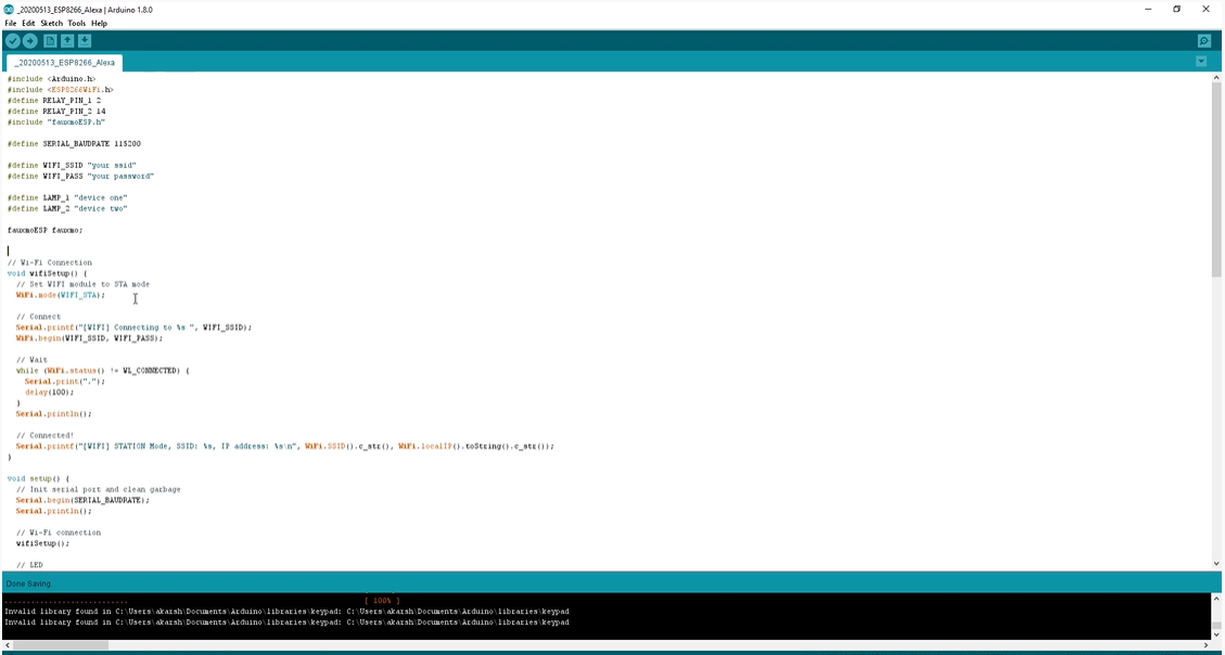
1. Download the code for connecting and controlling ESP8266 with Alexa from here.
2. Open the code in Arduino IDE and make the required changes to the SSID/Password at the top of the code.
3. Navigate to Tools > Board. Select the appropriate board that you are using NodeMCU(12E) works in most of the cases.
4. Select the correct comm. port by going to Tools > Port.
5. Hit the upload button.
6. When the tab says Done Uploading you are ready to use the device.
-
8The Relay Switches on Command to Alexa
After the code gets uploaded:
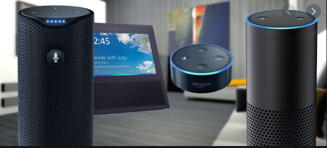
1. We can bring in the Alexa device and ask her "Alexa,Discover devices".As our device initiates in the pairing mode it will be discoverable to Alexa.
2. When the discovery device screen goes off,it shows that device is discovered and added.
3. Try it out with saying "Alexa,Turn On " in my case i have given names "Device1" and "Device 2"
You would be able to see that the relay turns on and off as we give commands to Alexa.
In this way you can control as many home appliances as you want using suitable relay module and making relevant changes in the code.
That's it from this demonstration!
Control Home Appliances through Alexa with ESP8266
Control your home appliance through Alexa using just ESP8266 or ESP32 for under $5. Voice-activated smart appliances!

Discussions
Become a Hackaday.io Member
Create an account to leave a comment. Already have an account? Log In.