This design is based on the stc89c51/52 SCM design of temperature and humidity alarm system.
Step 1: Function Description
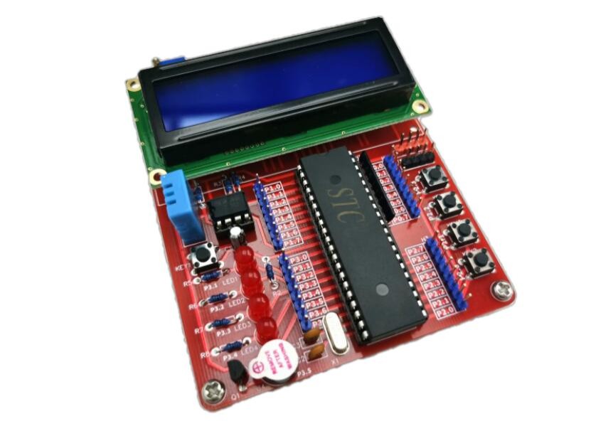
1 There are four separate buttons with functions of setting, adding, subtracting, and determining, which can adjust the alarm threshold.
2 The design USES AT24C02 memory chip, in the case of power loss can still save the set alarm threshold;
3 This design USES LCD1602 liquid crystal display, the top line shows the current temperature and humidity, the bottom line shows the corresponding cold, hot, dry, wet situation;
4 The full font temperature and humidity sensor DHT11 is selected, which has a wide temperature measurement range and can meet the general requirements.
5 When the temperature or humidity exceeds the range of threshold value, a buzzer will alarm, and a corresponding LED alarm light will be lit.
Step 2: Design Features
PCB: 82 × 100 mm JLCPCB provides 5 pcs 1-2 layers PCB samples only by $2; 4 layers boards by $5
All other components except the power supply socket are directly inserted for easy welding.
Use micro USB power.
Step 3: Schematics

PCB Design tools suggest using EasyEDA
Step 4: PCB File

For more specific files needed, please feel free to visit JLCPCB

 jaromir.sukuba
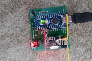
 David Plass
 twl
twl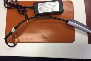
 fr.shirvan
You need more than just a board to make this project work. The STC89C52 needs to be programmed using its serial bootloader. A development board like the one I described in #Adventures with a STC89C52 development board is needed, as well as the software toolchain to develop the software.